overpro
-
Posts
158 -
Joined
-
Last visited
Content Type
Profiles
Forums
Events
Everything posted by overpro
-
an Arduino USB HID controller, composite USB controller
overpro replied to overpro's topic in Home Cockpits
Hi Robert, You need to uncomment one line of the ARDUINO code, please scroll down to the very end of the arduino sketch and you will see this: for (uint8_t ind=0; ind< NUM_AXES; ind++) { [b][color=Blue]//[/color][/b] joyReport.axis[ind] = map(analogRead(54+ind), 0, 1023, -32768,32767 ); } As you can see I have comment out the code that read the analog input, so you just need to delete the two slash symbols ( marked in blue ) and re-program the board. Please note that for all unused analog pins you need to short it to GND ( ground ) or the corresponding axis will jump like crazy. Please let me know if it works for you. Regards -
an Arduino USB HID controller, composite USB controller
overpro replied to overpro's topic in Home Cockpits
Hi Peter, Yes, it's the scan timing issue, I'd recommend to change the ARDUINO code like below to have a try, it will try to catch more "pulses" //if (EncoderState[encoderId] == CWPattern1 || EncoderState[encoderId] == CWPattern3 ) if (EncoderState[encoderId] == CWPattern1 || EncoderState[encoderId] == CWPattern3 || EncoderState[encoderId] == CWPattern2 || EncoderState[encoderId] == CWPattern4 ) { //this is a full CW pattern, direction = 1; } //else if (EncoderState[encoderId] == CCWPattern1 || EncoderState[encoderId] == CCWPattern3 ) else if (EncoderState[encoderId] == CCWPattern1 || EncoderState[encoderId] == CCWPattern3 || EncoderState[encoderId] == CCWPattern2 || EncoderState[encoderId] == CCWPattern4 ) { //this is a full CCW pattern, direction = -1; } And could you let me know the specs of your encoder? Maybe I can give it a try from my side as well. Regards -
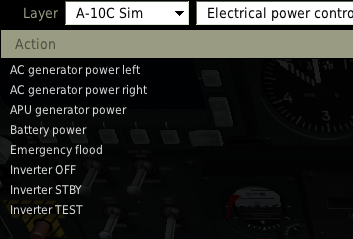
As the attached image shows, some switches on/off state is combined as one action, for example: AC generator power left, AC generator power right, APU generator power, Battery power, Emergency flood ... ... There is no separate action such as AC generator power left ON, AC generator power left OFF. So I'm unable to map the APU generator power on and off to 2 different button on my USB game controller. That's say if I use an On-Off toggle switch on my usb controller then I need to flip it on and off to make the APU generator power goes ON, and then flip it on and off again to make the APU generator power goes OFF. If I make the Game controller to generate a same button push signal no matter I flip the toggle switch ON or Off, ( for example: flip to ON generates BUTTON9 press signal, flip to OFF also generates BUTTON9 press signal ) then I can make it works as expected, BUT...... if my toggle switch position is out of sync when simulator starts, then these toggle switches will be always in an inverted state compared to the simulator. So I'd like to seek recommendations from you on how to resolve this issue. Thanks in advance. Regards

-
an Arduino USB HID controller, composite USB controller
overpro replied to overpro's topic in Home Cockpits
I think it's possible, grab the data from DCSW and send the data to the board by using USB protocol, I haven't tried it before. The firmware part need some changes, add an OUT endpoint, so arduino knows how to interpret the data received from Host. -
an Arduino USB HID controller, composite USB controller
overpro replied to overpro's topic in Home Cockpits
UNO digital pin 2~13 can be used so there are 12 pins, which can support 6 * 6 = 36 buttons. -
an Arduino USB HID controller, composite USB controller
overpro replied to overpro's topic in Home Cockpits
Hi don_sangria, there are 16 analog inputs on mega2560, this arduino sketch uses A0 ~ A8, and if you uncomment that line and upload the sketch, without flash it to USB HID controller you can monitor the data output by using serial monitor ( I use HTerm ), every first 16 bytes of each 46 bytes ( 16 bytes for axis and 32 bytes for buttons ) are the analogRead's data. If you don't shortcut any analog pin to ground then the pin works like an antenna so those bytes looks like totally random. Please let me know if your have any progress. -
an Arduino USB HID controller, composite USB controller
overpro replied to overpro's topic in Home Cockpits
Yes, you can, but I commented out the analogRead code in arduino source code, you can simply uncomment that line at 297: 296 for (uint8_t ind=0; ind< NUM_AXES; ind++) { 297 joyReport.axis[ind] = map(analogRead(54+ind), 0, 1023, -32768,32767 ); 298 } mega2560 's analog pin has a 10 bit resolution, so we just need to map [0, 1023] to [-32768, 32767] this line of the code might take a long time to run, which might have side effect to the rotary encoder, so I'd recommend you to do some test, and it might be worth to replace analogRead() to avr style function calls if available, same to map(). -
an Arduino USB HID controller, composite USB controller
overpro replied to overpro's topic in Home Cockpits
Hi Sifhanar Please have a look at the message at 8th floor : http://forums.eagle.ru/showpost.php?p=1935590&postcount=8 -
Yet Another CMSP character recognition application
overpro replied to overpro's topic in Home Cockpits
vhfam preset value: GetDevice(0):get_argument_value(137) FM: get_argument_value(151) UHF: get_argument_value(161) Is it what you are looking for? -
Yet Another CMSP character recognition application
overpro replied to overpro's topic in Home Cockpits
Hi devon, i think the radio freq can be exported by using export. lua. http://en.wiki.eagle.ru/wiki/Export_1_0_1 -
Yet Another CMSP character recognition application
overpro replied to overpro's topic in Home Cockpits
Let me make some code cleaning and put it to github. -
Hi Gadroc, it's exactly like you said, the do while loop will block other needles movement, so I'm thinking use another board to control just one Altimeter.
-
To be precise, other indicators will show wrong (not up to date) value, because they move very very slow while arduino focus on moving the Altimeter needle. Here is a case: do a -90 vertical dive from 30000, and after below 10000 the engine will stop for some reason, the altimeter needle moves very fast and many EMI needles move towards zero position at the time. But my EMI needles doesn't move. If I can save my plane from dive the altimeter needle will slow down, then my EMI needles can catch up the visual needle in 0.5~1 second.
-
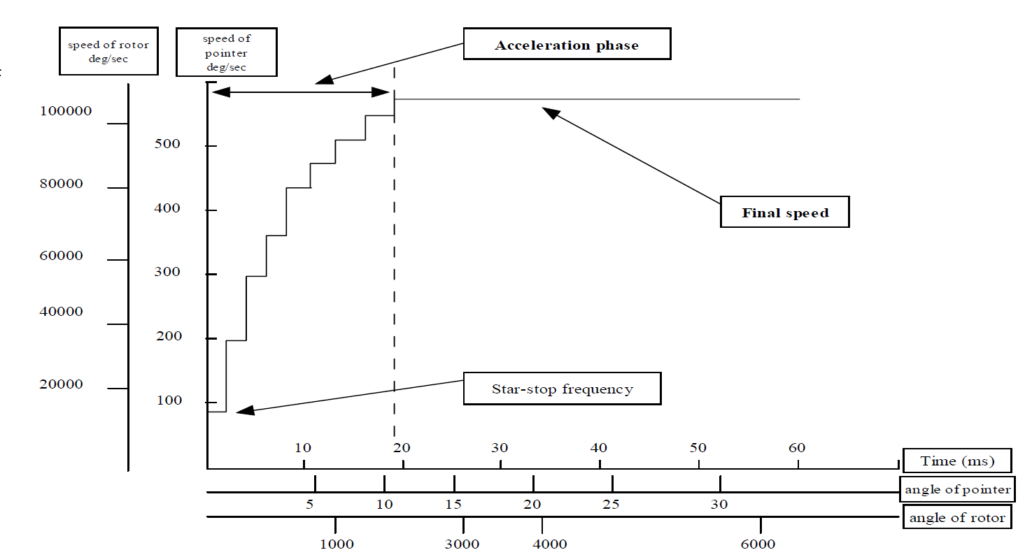
Ok, here is an update: This stepper motor---VID29 has a 125Hz start driven frequency and has a maximum 600Hz driven frequency, that means if I want to make the pointer go full speed, I have to delay 1/125 seconds for the first step and then decrease the delay time for the further steps gradually, until the delay time decrease to 1/600 seconds. This is the screen capture from the stepper motor's specification: So I have changed the code to this: [b] int delayMs = STARTDELAY;[/b] for ( int i= 0; i < abs(step); i++) { if ( di == 6 ) { di = 0; } else if ( di == -1 ) { di = 5; } digitalWrite( 2, (drivePattern[di] & 1) > 0 ? HIGH : LOW); digitalWrite( 3, (drivePattern[di] & 2) > 0 ? HIGH : LOW); digitalWrite( 4, (drivePattern[di] & 4) > 0 ? HIGH : LOW); digitalWrite( 5, (drivePattern[di] & 8) > 0 ? HIGH : LOW); [b]delayMicroseconds(delayMs);[/b] [b] if (delayMs > FINALDELAY[/b][b]) delayMs -= 20;[/b] //decrease the delay time gradually } The test result is good, at the 30000 feet and do a -90 degree vertical dive the real pointer can catch up the visual pointer all the time.
-
Hi Hawk4base, My currrent export.lua provides data feeds in 20ms interval. the time for one loop() in my arduino code is around 7~9 ms. Is it to say I need some code/algorithm to compensate this delay? Could you provide some more details on this? Many thanks
-
I'm using Arduino Mega2560 and some other chips including 595 to control all the stepper motors : 12EMI, 2 Hydraulics, 2 Fuel, 1 VVI, 2 Airspeed, 1 Flap, 1 AoA, 1 G, 1 Altimeter, 3 environments = total 27 stepper motors. If the code put too much time on altimeter then other stepper motors will not move until altimeter reach the target position. I made a test and the algorithm like this: If the altimeter behind more then 2 steps of the visual needle, then the code will enter into a while loop to try move the needle to the target position: while( AltimeterPosition != TargetPosition ) { AltimeterOneStep(CWorCCW); delayMicroseconds( 800 ); // this is the required minimum delay, or the motor will lose steps. } By using this approach I did this test: doing a -60degree deep dive from 30000 feet and when the altitude below 10000 feet the delay appears, Yes, the delay is still there but better then before. The side effect is this will lead other needles stop, unless altimeter catch up the target position. It seems that move the altimeter to another arduino board is a better choice. I tried the maximum speed of this motor, it's about 0.89 second per round.
-
I'm using Arduino Mega2560, The code check the deviation between stepper motor and visual indicator when the data is received from export.lua, the problem is if the visual indicator's RPM is higher then the stepper motor limitation then I have nothing to do.
-
There is a photo reflective sensor, you can see it emits infrared light, at the beginning of the video. The first 6 seconds is the "go zero" process.
-
The stepper motor is the same one I used in the EMI panel: http://forums.eagle.ru/showthread.php?t=115997 The current unresolved issue is if in-game pointer goes too fast, I can't make the stepper motor catch up. But it will try to match the position by using the shortest path.
-
an Arduino USB HID controller, composite USB controller
overpro replied to overpro's topic in Home Cockpits
Hi Trueno, here is a detailed instruction from Arduino.cc website: http://arduino.cc/en/Hacking/DFUProgramming8U2 You might want to check this first. -
an Arduino USB HID controller, composite USB controller
overpro replied to overpro's topic in Home Cockpits
Good to know :) -
an Arduino USB HID controller, composite USB controller
overpro replied to overpro's topic in Home Cockpits
Well, this is weird, I haven't had this issue before. Are you using Flip 3.4.7 build 112? Regarding the rotary encoder, it's just the normal type: 20 pulse per round, like this: http://www.ebay.com/itm/20pcs-lot-12mm-Rotary-Encoder-Switch-W-Keyswitch-HQ-New-free-shipping-/261299009115?pt=LH_DefaultDomain_2&hash=item3cd6a2765b -
an Arduino USB HID controller, composite USB controller
overpro replied to overpro's topic in Home Cockpits
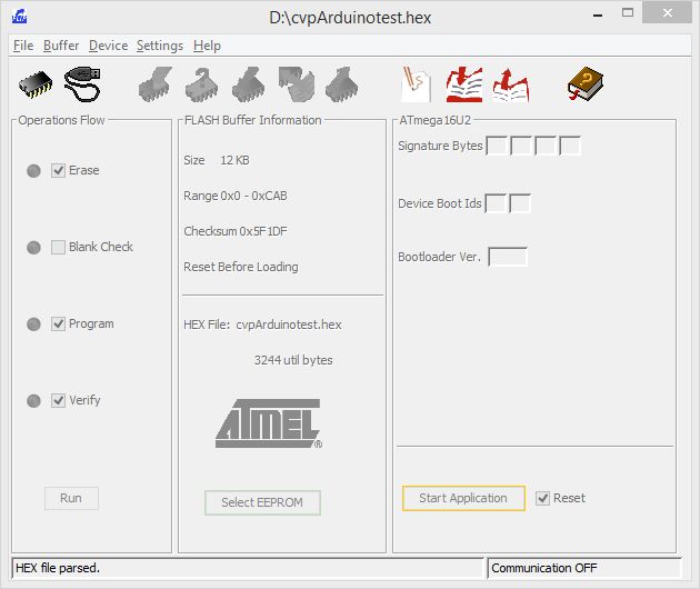
Hi usul, you need to extract cvpArduinotest-131126.zip, and use flip to load the extracted file: cvpArduinotest.hex, Flip will report "HEX file parsed".
-
an Arduino USB HID controller, composite USB controller
overpro replied to overpro's topic in Home Cockpits
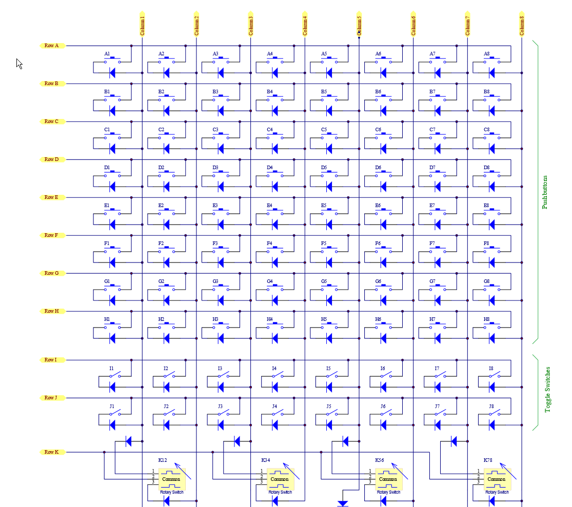
This diagram is borrowed from MJoy16 document, the schema is almost identical, except we have 16 rows and 16 columns, and Row 1~4 are reserved for rotary encoders. Please note that the diode is 1N4148, and this is REQUIRED to eliminate the ghost effect. If you just want to perform some basic test, just wire the button's two pin to row / column pin: Please note the row 5 ~ 16 should be used for button / toggle switch. or you can test your rotary encoder as well, please note Row 1~4 are used for rotary encoder.
-
an Arduino USB HID controller, composite USB controller
overpro replied to overpro's topic in Home Cockpits
If you have programmed your MEGA2560 yesterday please flash the USB firmware back to normal MEGA2560 and reprogram the arduino sketch by downloading the sketch from github page. And use the latest USB firmware in the top post. Some error were fixed.