KonusVector
-
Posts
7 -
Joined
-
Last visited
-
That looks nice. Did you cable it already? If y maybe give us an inside. I am planning currently all switches and pottis etc. with an array of shift registers to use at the end only a arduino nano or uno But i am beginner in this stuff so might not end like i want.
-
Just a short update. For all who are interested in the spacer I have to print, here are the STL Files for appx. 2mm and 3mm with additional distance holders. With this that the spacer is always correctly adjust to the matrix and not moving around anymore while glueing it. Disadvantige of it, when ever you have to remove the PCB it will be blocked from the distance holders. Greetings! Matrix Spacer 2mm.stl Matrix Spacer 3mm.stl

-
A late but not forgotten thanks
-
Can you link those LCD´s as I only find 1x16 lcds with a hight of 33mm which not fitting. Thx a lot!
-
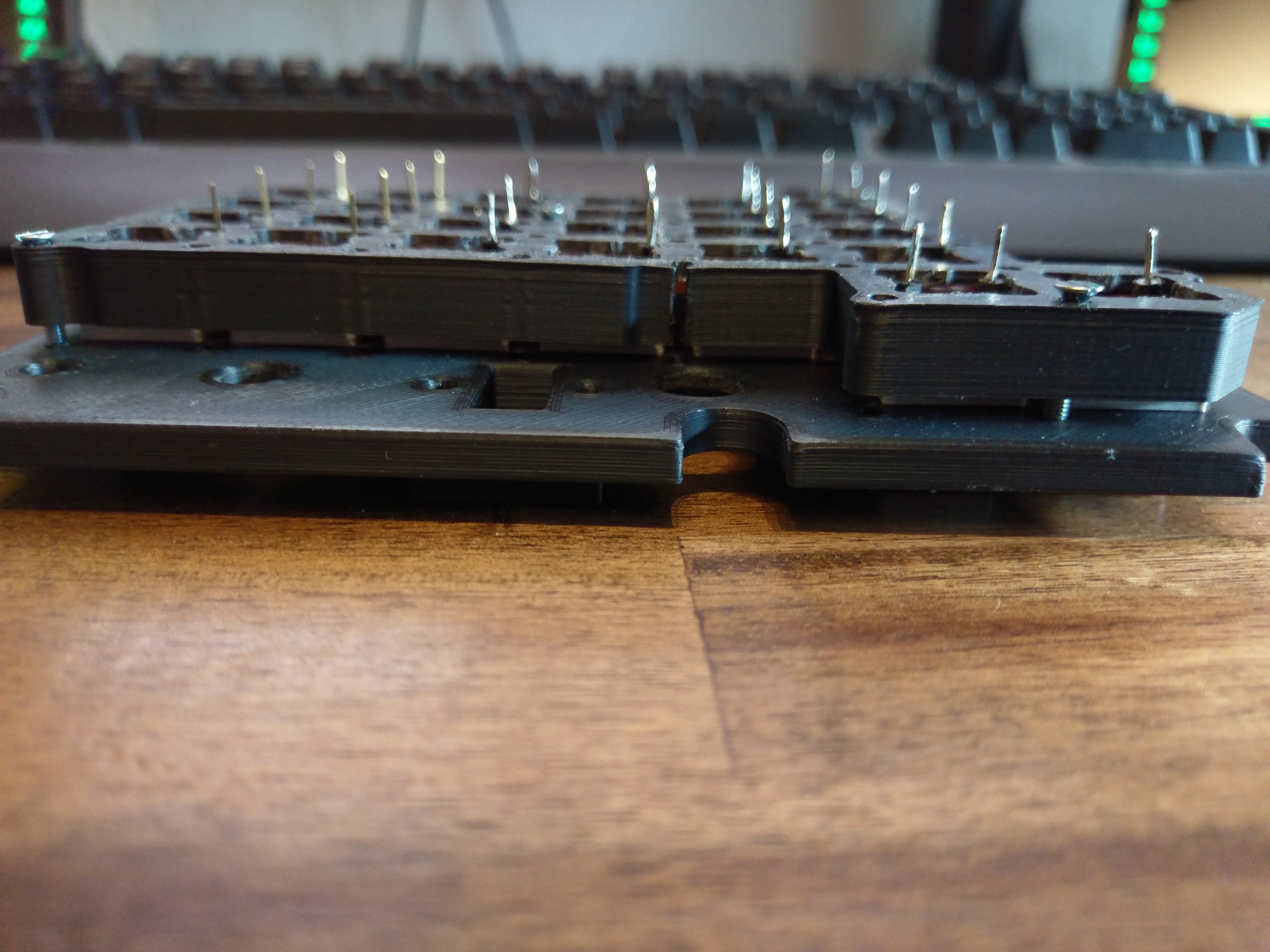
Sorry for the late reply. The Idea which you have is not bad, but you have to think the other way around. You need switches with shorter stems. When you look the "sandwich" there is a gap of about 2 mm. The printed buttons are already touching the push buttons in order to have no movement. If you longer the the stems now, it would push the back even further away, thats why I need a spacer between those two layers. Which is not printed yet as my friend is busy currently.
-
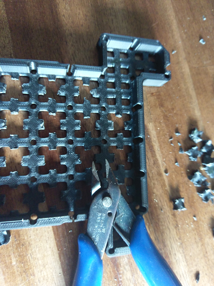
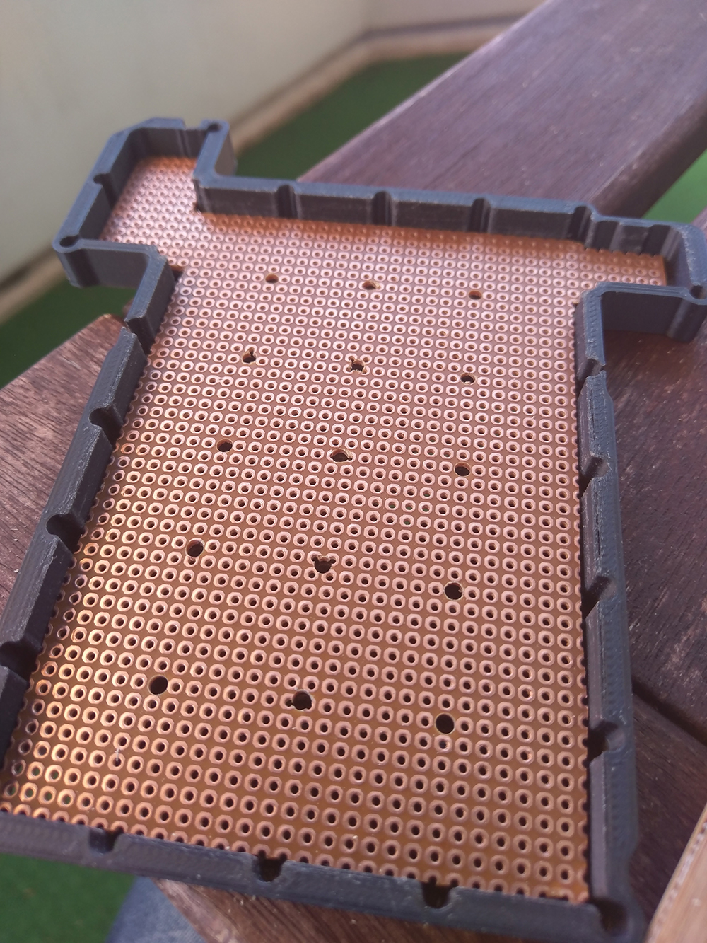
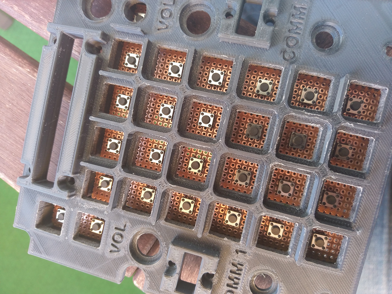
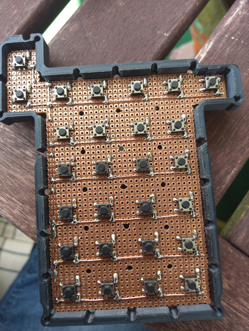
Hi all, I am following this topic already some weeks and I am first of all thanks for the template of the UFC of the Harrier and going to donate some bucks for your work. So here is my outcome. I am still working on the button field and wanted as to be as simple as possible. The original idea to glue/mount the push buttons on the matrix where for me not stable enough so I thought that a PCB would work nicely and giving it additionaly more support while pressing the buttons. So here is what I did. I cut out the actual holders from the matrix as they interfered with my idea. The depth of the matrix to the upper front of the UFC gave me enough room to solder inside and to put some jumper bridges. And for all, thats the second time in my life i have been soldering something The first time was creating my head tracking back about 10 years ago. Thats where I am standing currently. I am trying to find out a way to fix the three Lcd´s / Oleds. But as the space is so enourmusly thight in there I reccommend replaning the Lcds and potentiometers around the matrix to be slightly bigger to fix maybe a 1x16 lcd. @Obius When you read my little post, I would love to maybe get in contact with you to replan this As I have put a PCB in between now, the hight is not matching anymore. When you insert the printed buttons, you will have a gap between the matrix and the front of the UFC of about 2 to 3 mm. A friend of mine prints me this items and I am currently wait for a additional spacer, which I will hotglue between those two parts. For all who were asking about cabeling, thats my sollution Sorry for my English as I am not a native speaker. I hope you will find this interesting and usefull. Please feel free to copy Michael
-
I am pritty new to this aircraft and try to figure out what you mean with CTD. Could not find this abbreviation even in the Razbam Pocket Guide for the Harrier. Thanks a lot even the topic is a bit older.