

98abaile
-
Posts
717 -
Joined
-
Last visited
Content Type
Profiles
Forums
Events
Posts posted by 98abaile
-
-
On 6/5/2024 at 11:16 PM, Hempstead said:
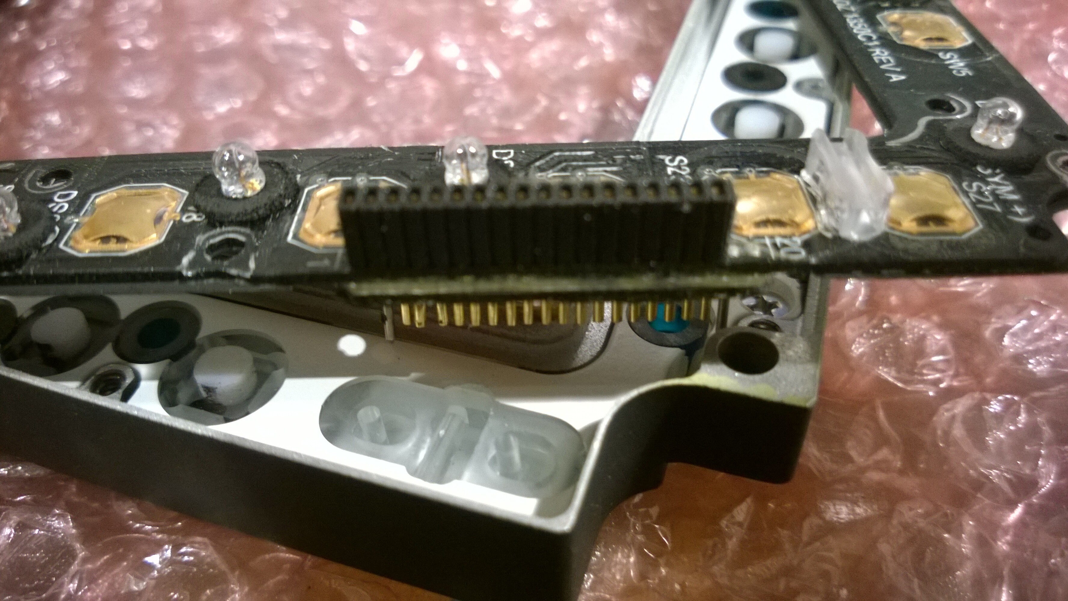
Just received the ICP PCBs. It fits perfectly!
I am still waiting for the newer version of Hall sensor PCBs ordered from OshPark (and the main ICP PCBs too, which I forgot to "unmask" the main contact rings of the dome switches; so I will have to grind them off).
The ICP main PCB is designed with KiCAD (I have ditched EagleCAD since AutoDesk acquired them.). The Hall sensor PCBs, however, are years old so it's still in EagleCAD format.
https://blog.hempstick.org/2024/06/f-16-icp-pcb-made.html
Did you really need 2 micro processors? Why not a multiplexer? You'd only require the one USB input then and it wouldn't appear in game as 2 separate controllers.
-
Just downloaded the new updater. Avast keeps flagging it and quarantining it. The threat name is given as IDP.Generic.
-
I've purchased it through the shop and authorised paypal payment, but it's just been stuck in payment processing for a good while now.
EDIT: I changed my payment method. It's apparent that paying by paypal is having issues.
-
It's not possible anymore I think (at least not legitimately) and I think is now forbidden by ToS.
-
Install SRS anyway. Most multiplayer servers use it still and there's nothing stopping you having both and using whichever is applicable.
-
 2
2
-
-
I know you want them from within the EU, but those LED buttons are dirt cheap from aliexpress and arrive fairly quickly.
-
1
-
-
I can't find anything below 5 euro.
https://uk.rs-online.com/web/p/rotary-switches/7118394
https://uk.rs-online.com/web/p/rotary-switches/1616634
I can't imagine a project where you'd need a tone of them though.
-
Are you really that worried about a significant number of forum users having multiple accounts?
-
1
-
 1
1
-
-
In the vein of knowing what you don't know, if you do use encoders with arduino code instead of DCS-BIOS, make sure you know what the interrupt pins are for your chosen board (0, 1, 2, 3, 7 for a pro micro) and make sure you keep them for encoder use only. As I said, in my experience programming encoders in arduino is a pain and I'm only just getting to grips with my own project that uses encoders, everything else works fine. Some encoders send 1 pulse per click, some send 2 pulses and some even send 4 and you have to code around them if you don't want multiple button presses with each click.

But yes, general workflow is figure out all the functionality you need (including limitations like space, and what compromises you're willing to make) and lock that down first, then figure out the switch requirements, then the hardware requirements. Also don't be afraid to ask questions or for assistance.
-
23 hours ago, BaronVonVaderham said:
Hey guys,
what’s your experiences with using PCBWay as a supplier when based in Europe?
To be a bit more specific, I’m wondering about order quantity for the same pcb.
most of us typically only need a single pcb, maybe two at most, for each panel. That’s relatively expensive for them (and thus for us). However, if I order, say, 10 different PCB’s, does that compensate, or is there still a desired minimum for each pcb?
i noticed that some communities tend to order bulk for those that want to participate.
The other is about delivery times and prices to the eu. How fast/expensive are they in practise?
Finally, what’s the general quality like?
Pretty sure the minimum for each PCB design is 5. If you want pick and place assembly, it's 2 assembled green boards or 5 in any other colour.
Delivery took about 2 weeks when I used them.
EDIT: Sorry, I just remembered that I used JLCPCB, but I think it's the same for PCBWAY.
-
1
-
-
On 1/14/2024 at 7:44 PM, Deadman said:
Do you know if metal dome buttons are standard for real panels or is it a mix?
-
On 2/2/2024 at 1:58 PM, Drakeshoot said:
Hi all,
I’m planning on building my first button box, the Weapons Control Panel & extras for the upcoming F-4E. This means I need rotary encoders with push (weapons select, stores jettison etc), a couple of rotary potentiometers (bomb release interval and probably course & heading knobs), some on-on switches (master arm and CW Interlock), some on-on-on switches (nose-tail fusing switch) and a pair (on)-on-(on) switches for AFCS and Alt hold.
I appreciate the last pair are magnetic in the real jet but sometimes they don’t engage in the F-14 due to me being out of parameters so I’d like a return to centre so I can repeatedly send “on” signals rather than having to manually cycle the switch to keep in sync with the cockpit.
In order to achieve this, I’ve got a arduino and a bunch of switches, pots and rotaries in the post but I’ve already hit my skill limit. I don’t know how a circuit works, I can’t solder and I can’t code. I’m going to have to learn these things, which is fine, I’m looking forward to it, but I do need someone to idiot check me at this point.
I'm pretty sure the Arduino UNOs I ordered (got a pair just in case one was DoA) won’t have enough pins to manage all of these inputs so I’m going to get a Mega. Can I bolt 2 UNOs together instead with a single USB out, or is that a level of complexity I don’t want to be messing with yet?
I found Circuito.io with an auto wiring tool which is massively helpful in making me think about wiring up (don’t forget, I haven’t got a clue), it doesn’t have many switch options though, is there a similar tool with more input options?
Am I approaching this in the right way? Is there anything I’m missing?
Thanks for taking the time to read this, I’m very excited, but also utterly incompetent so any advice would be gratefully received.
Always start with the design requirements, design the panel first. Decide exactly what you want to include or exclude; decide the layout and what compromises you're willing to make (you don't need true to life panels in a non true to life gaming setup), THEN decide what hardware you need. For now the coding part seems like the biggest hurdle because you've never done it before, but really once you understand it it's more tedious than hard. It's A LOT easier to change the code after the fact than it is to have to redesign and rebuild the panel though. Design the panel first.
As to your stated idea, as an example, here's what I'd do:
If it were me, looking at the real panel, I'd ditch the instrument brightness knob and move the fuse selector switch lower in order that everything can fit on a rectangular panel. If I didn't have one I'm working on already, I'd include a switch for the landing gear lever where the AoA dial would be. Since I play in VR exclusively, I've no need for the LED indicators, so I'd use cheaper switches with custom caps; this avoids having to buy or design/make specialised buttons and also means I can avoid having to wire or program any LEDs; this also means I wouldn't require DCS-BIOS, so I could make it a generic (albeit oddly laid out) button box.
Next, because rotary encoders are a pain to code outside of DCS-BIOS, I'd need to decide if I wanted to use them for most of the knobs (making it more generically useful) or not. Assuming I wanted to keep some sense of immersion, I'd use 12 position and 8 position rotaries for the qty selector and weapon selector knobs, the AWRU knob could be a potentiometer but I'd be specifically looking for one with 270 degrees of rotation (which is most cheap ones). The delivery mode knob has a centre push but the label implies it's only for jettisoning nuclear weapons; I'd have to ask if that functionality is even in the game, because if not I could be using a 16 position rotary pined for 13 positions instead (NOTE: 16P rotaries are expensive, so in reality I'd probably use an encoder anyway, but for this example we'll assume a rotary). The only knob that would give me a headache would be the selective jettison knob. It's an 8 position rotary using 7 positions, but the issue is the need for a centre push. I've done it before on another panel with an encoder (with push), but what if I wanted to make it more realistic instead? For arguments sake, let's assume I'd found a way to use a rotary instead.
With the hardware figured out, we can work out what inputs we need.
We need two analogue inputs (one for the AWRU knob and one for the dimmer next to the pylon indicators). The two position switches only need 1 input (since the off state can also be coded for or just setup in game), similarly the 3 position switches only need 2 inputs. This gives 19 digital inputs plus 2 for the landing gear lever I specified earlier (I used a 3P switch in mine), so 21 digital inputs so far. Now comes the question how many digital inputs would we need for the rotaries? By my count it would require 39, giving us a total of 50 digital inputs required.
With 50 digital inputs and 2 analogue inputs (and no outputs) we can now decide what controller to use. With that many digital inputs, we'd need an arduino mega (54 digital inputs available), knowing that we could now design the enclosure. This would also be the simplest to wire and program.
However since I've already got experience with coding multiplexers, I could use 3X 16 channel multiplexers and reduce that pin count to 8 digital pins and 2 analogue, meaning I can now use a pro micro instead.
Now let's assume I'd selected encoders for the delivery mode knob and the sel jett knob. That's 16 less inputs required and one gained for the nuclear jettison; leaving us with 35 digital inputs. The problem is that encoders don't work well if at all with multiplexers, meaning we need 4 pins wired directly to the board. So 31 inputs using 2 multiplexers and 4 directly connected inputs means I would need 10 digital pins and 2 analogue pins.
If I replaced all the rotaries with encoders, I'd have 21 inputs I'd still need 2 multiplexers for and now 8 digital inputs straight from the board, which equates to 14 digital inputs and 2 analogue. If I weren't using encoders I'd need 29 digital pins, so I would need something bigger than a pro micro.
EDIT: ...and then I found out 5 of those buttons were just lights. I can't be bothered to change the above text now.
-
2
-
1
-
-
I got mine installed and I like it, the new damper is amazing too. My only complains aren't to do with the grip at all, I'd like to mount the collective about 2 inches lower but there's no combination of the mounting hardware that would let me do that (I've got some aluminium spacers on the way).
A point people should look out for: just because you have the new damper installed doesn't mean you can completely undo the clutches. If you slacken the clutches off fully you'll find the shaft wobbles quite noticeably. My advice would be to lube the clutches with silicon grease and then tighten them just enough to remove the side to side play.
-
1
-
-
The obvious question should be: Why are ED using turn servers rather than letting the game servers handle their own VoIP data?
-
1
-
-
Got mine today (after DPD didn't bother on both saturday and sunday despite saying they would).
Lighter than I thought it would be. It's also a tight fit if you have big hands.
-
1
-
-
I would also very much like a radial menu. I don't want to fumble with keys or a mouse in VR any more than I have to, I'd rather just turn my head.
-
As the title says, can DCSbios actions use booleans stored in an array rather than digital pins?
For example:
A normal action would be:
DcsBios::Switch2Pos ufcMasterCaution("UFC_MASTER_CAUTION", 10);Would I be able to instead use:
DcsBios::Switch2Pos ufcMasterCaution("UFC_MASTER_CAUTION", muxArr[15]); -
I got the solution from discord. The problem was that I hadn't set my muxSIG pin's internal pullups. Changing the pinmode from INPUT to INPUT_PULLUP fixed the issue.
-------------------------
I'm wondering if anyone can help me with my attempt at using a multiplexers? Here's the code I have so far:
#include <Arduino.h>

const int muxSIG1 = 2;
const int muxSIG2 = 3;
const int muxS0 = 15;
const int muxS1 = 14;
const int muxS2 = 16;
const int muxS3 = 10;

int SetMuxChannel(byte channel)

{
   digitalWrite(muxS0, bitRead(channel, 0));
   digitalWrite(muxS1, bitRead(channel, 1));
   digitalWrite(muxS2, bitRead(channel, 2));
   digitalWrite(muxS3, bitRead(channel, 3));
}

void setup() {
  //Joystick.begin();
  pinMode(muxSIG1, INPUT);
  pinMode(muxSIG2, INPUT);
  pinMode(muxS0, OUTPUT);
  pinMode(muxS1, OUTPUT);
  pinMode(muxS2, OUTPUT);
  pinMode(muxS3, OUTPUT);
  Serial.begin(9600);
  delay(1000);
}

void loop() {
  for (byte i = 0; i < 15; i++) {
    SetMuxChannel(i);
    bool a = digitalRead(muxSIG1);
    bool b = digitalRead(muxSIG2);
    Serial.print("Push button at channel "); Serial.print(i); Serial.print(" is "); Serial.println(a == LOW ? "pressed" : "not pressed");
    Serial.print("Push button at channel "); Serial.print(i+15); Serial.print(" is "); Serial.println(b == LOW ? "pressed" : "not pressed");
    delay(1000);
  }
  Serial.println();
  delay(1000);

}
Unfortunately all that happens is that all buttons show as constantly pressed.
I know the wiring is fine since the same setup works just fine in Mobiflight and everything works as expected.
-
10 hours ago, Dogmanbird said:
I'm using a leap v2.
Although my hands in front have always tracked extremely well, I've discovered that by using IR spot / flood lights, I can significantly improve both hand and finger tracking stability within the outer peripheral areas. Placing the lights at each side of my head with some diffusion to soften the shadows, I've pointed the lights at where my hands would be when operating dials/ switches on the side panels.
This has given me reliable hand tracking everywhere within the leap control config window (easily outside of my VR headset's FOV) with near and far hand placement . If the hands leave the window, it instantly picks up the tracking when part of a finger or hand re enter the window. It's made pointing at anything very reliable and consistent. Finger tracking has improved a lot too, but I still prefer to use hotas buttons or ring mouse for that.
I accidentally came across this because I decided to try it with window blinds open and diffused sunlight flooding the area I sit, and realised the overall tracking had greatly improved, particularly at the edges of my FOV
Not sure if this is old news, but I've also found turning the pilot body off noticeably improves tracking, particularly if part of the body is close to a switch I wish to operate.
Can you show us your setup? It sounds like you've got some lamps strapped to your head.
-
1
-
-
I don't use them either. They might be more useful if you have a vive setup that can track them outside your field of view, but having to contort yourself to see the switches and then try to use them while keeping them in view (especially with arm rests) is just too cumbersome. So much easier to just turn your head and use a regular mouse.
-
Remember to save the configuration once you've changed the bindings.
-
Agree with this. It's confusing.
-
3
-
-
2 hours ago, RafaPolit said:
I get a very large warning that I ALREADY HAVE THIS PRODUCT when trying to buy Normandy 2.0
Should I wait? Is it OK to go ahead? cc @NineLine
Getting the same problem too.
-
On 3/29/2023 at 12:28 PM, lesthegrngo said:
Hi all, I have the Lulzbot Mini FDM 3D that I bought many years ago, and lately I have been using it a bit more when making bits for the sim rigs. I essentially have been using ABS, but that's more because it's what I have rather than it being the best. When printed properly it does have good mechanical properties, but it does tend to warp for larger parts and you can get layer tearing too.
Looking online it seems that ABS has fallen out of favour a bit, so I want to know what you guys use to see if changing the filament makes my parts any better. I am looking for a good all rounder, one that prints easily, is reasonable for strength, good dimensional stability and isn't finicky. If I want a part for strength I generally design it so that it has metal or another material inserts that will take the bulk of the load, and if I want super surface finish I would use the resin printer to provide that, with maybe a sub-frame printed on the FDM printer to give it more strength.
I was (for a short time) looking at carbon fibre filled filament but that's expensive and from what I read seems to not live up to the hype
So what do you guys use?
Cheers
Les
ABS used to be the go to simply because it's what was available when consumer 3D printers first started appearing. As for its properties, it has better impact strength, but that's not really an issue for our purposes. It also tends to yield and deform whereas PLA it more brittle. Realistically unless heat is an issue, there's not much advantage to using ABS over PLA. ABS will have better layer adhesion but you can (and where possible) design around that. That's really the crux of the issue here though; how you print matters far more than what you print with. So you should be designing with metal hardware, walls, stress relief and layer orientation in mind, also using tricks like a 0.01mm wide void within a part to trick the slice into creating internal structures with walls (most of a part's strength comes from its walls, infil does very little). Sounds like you already do that though.
As for what material to use, PLA+ is my go to. It's stronger than regular PLA and still very easy to print.

Terrain topography as point clouds?
in Chit-Chat
Posted
Which resource is it less demanding on? It may be less computationally demanding, but how much data will it require?