Hansolo
-
Posts
1775 -
Joined
-
Last visited
-
Days Won
1
Content Type
Profiles
Forums
Events
Everything posted by Hansolo
-
Hello sir, First of all you may know this but I am just going to say it anyway. DCS-BIOS in it's current form doesn't support multiple air frames. So if you go with DCS-BIOS you can't easily switch between air crafts as the programming is done in the individual boxes. One my wing mates did some testing with using a switch to change which code got executed on the Arduino and that worked but takes some more skills. If you haven't tried DCS-BIOS before then start with something simple just communicating over USB. The RS-485 has been causing difficulties for some and I haven't been able to pin-point which seems to be the culprit. That being said Blue73 and myself are running many panels over RS485 and don't have any issues. For more information on RS-485 please check out the following; https://forums.eagle.ru/showpost.php?p=3791557&postcount=216 https://forums.eagle.ru/showpost.php?p=3789267&postcount=207 https://forums.eagle.ru/showpost.php?p=3247704&postcount=171 One of the important things when talking about DCS-BIOS over RS-485 is that you should use MAX487 chip not the 485 chip. Ian father of DCS-BIOS stated this a long time ago. Cheers Hans
-
You're welcome sir ???? Glad you sorted it out Cheers Hans
-
I actually wouldn't know Les, but from the looks of this it does look like it needs a different board; http://forum.hobbycomponents.com/viewtopic.php?t=2189 Cheer Hans
-
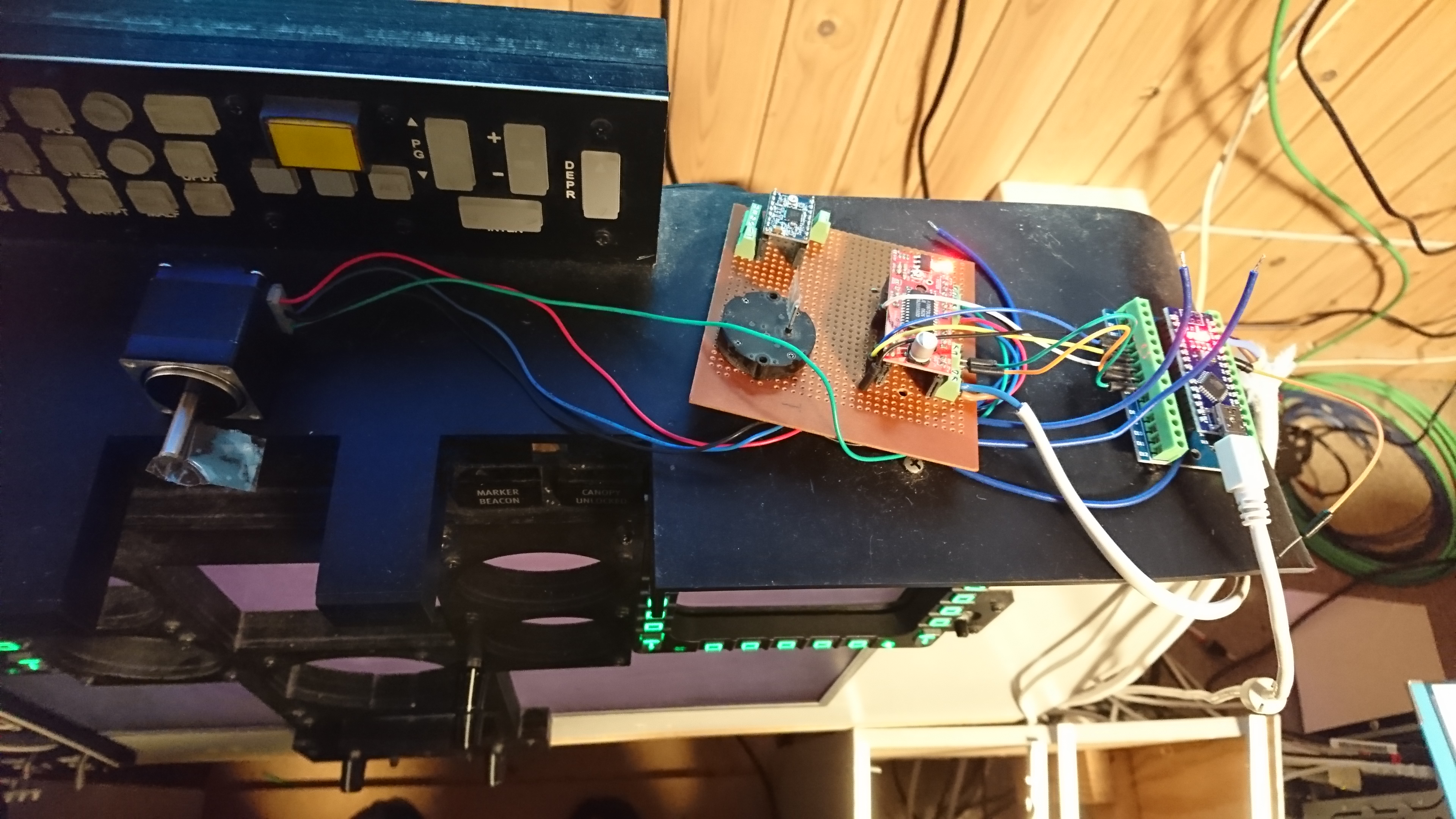
Managed to put a new board together this evening. What you see is two setups using Arduino Nano and EasyStepper. The one on the right is getting values from DCS via DCS-BIOS over USB. The one on the right is communicating with DCS via DCS-BIOS over RS-485. As far as I can see your schematics correspond with the way I set up system. Test was only about 12minutes. Cheers Hans
-
Have you done below, i.e. reverted the A10C.lua to it's original code? Because I can't get mine to rotate continuously between A and B. What type of rotary switch are you using? The reason (I think) for only compiling on old bootloader on PC might be because it's a never version on Arduino IDE. I never had the error before and I have been using same Nano's all along. Cheers Hans
-
Have you tried to run the stepper setup ‘non RS485 schematic 12V power USB’ outside your modular gauge controller? I mean on a breakboard setup or similar? I just ran same setup for 40 minutes and no issues so far. The EasyDriver chip was warm but not smoking hot. I ran at minimum current settings and it was enough to drive my Nema11 stepper. Cheers Hans

-
Try this; https://www.dropbox.com/s/izmxojksfrm4ros/Timer-master.rar?dl=0 There is am example included if you get it installed correctly Cheers Hans
-
I run all my Nano's on 12VDC and haven't gotten any issues. That being said I don't have any EasyDrivers connected. Can you make a sketch on how you have done your wiring and perhaps also some pictures for fault tracing? Thanks Cheers Hans
-
Yeah you should probably move that question to this thread instead as it is not related to DCS-BIOS. Cheers Hans
-
Nice pit you build there sir. Great job Cheers Hans
-
What are the specs for the LED's? Without knowing your LED specs I'd risk saying the resistor is too small. You need to look at the LED spec to determine the forward voltage and current. The total supply voltage minus the LED forward voltage is the voltage drop that need to be over the resistor and the specified LED current. https://www.kitronik.co.uk/blog/led-resistor-value-calculator/ I used tried with a standard green 5mm and the resistor should be almost 500Ohm. If your resistor is too small you end up damaging the LED in the long run. Cheers Hans
-
Question is if you want to use the rotary encoder or a rotary switch? If it is the former then you don’t need to do anything. You just leave your code as it was using; DcsBios::RotaryEncoder iffCode("IFF_CODE", "DEC", "INC", PIN_A, PIN_B); If you want to use a rotary switch then this is what you do; The modification of the A10C.lua didn’t work. I did a quick test and it’s a little more tricky than that so you forget about; defineTumb("IFF_CODE", 43, 3007, 199, 0.1, {0.0, 0.3}, nil, true, "IFF", "IFF Code: ZERO - B - A - (HOLD)") Please revert your A10C.lua to; defineFixedStepTumb("IFF_CODE", 43, 3007, 199, 0.1, {0.0, 0.3}, {1, -1}, nil, "IFF", "IFF Code: ZERO - B - A - (HOLD)") What you do instead is load following code; /* Tell DCS-BIOS to use a serial connection and use interrupt-driven communication. The main program will be interrupted to prioritize processing incoming data. This should work on any Arduino that has an ATMega328 controller (Uno, Pro Mini, many others). */ #define DCSBIOS_IRQ_SERIAL #include "DcsBios.h" #include <timer.h> Timer tm; int Code_dial_ingame = 1; // hold value from DCS //Define the inputs for rotary switch const int code_zero = 5; const int code_B = 6; const int code_A = 7; const int code_hold = 8; //IFF Code: ZERO - B - A - (HOLD) void onIffCodeChange(unsigned int newValue_Code) { Code_dial_ingame = newValue_Code; } DcsBios::IntegerBuffer iffCodeBuffer(0x111a, 0xc000, 14, onIffCodeChange); void setup() { DcsBios::setup(); pinMode(code_zero, INPUT_PULLUP); pinMode(code_B, INPUT_PULLUP); pinMode(code_A, INPUT_PULLUP); pinMode(code_hold, INPUT_PULLUP); tm.startTimer(200, setIFF); } int inputCode_dial() { int valueCode_dial; if (digitalRead(code_zero) == LOW) { valueCode_dial = 0; //ZERO } if (digitalRead(code_B) == LOW) { valueCode_dial = 1; //B } if (digitalRead(code_A) == LOW) { valueCode_dial = 2; //A } if (digitalRead(code_hold) == LOW) { valueCode_dial = 3; //HOLD } return valueCode_dial; } void loop() { DcsBios::loop(); tm.runTimers(); } void setIFF(int timer) { if (Code_dial_ingame < inputCode_dial()) { sendDcsBiosMessage("IFF_CODE", "INC"); } if (Code_dial_ingame > inputCode_dial()) { sendDcsBiosMessage("IFF_CODE", "DEC"); } } This is probably more eatable than my code but does more or less same. It reads the the input from your code dial and sets it’s value (variable valueCode_dial), then compares what ingame position is (variable Code_dial_ingame). If they are not identical then it will INC or DEC at intervals of 200ms. I have checked the code and it works The code you posed in #663 won’t compile at all as it is missing stuff primarily in the beginning. With the above code you don’t have to worry about DRRC, PORTC and similar. They are a vay for quickly checking multiple pins at the same time which comes in handy sometimes using mil-spec rotaries. There is a little more infor here on the subject; https://www.arduino.cc/en/Reference/PortManipulation Cheers Hans
-
Perfect sir. Glad you got it working. Cheers Hans
-
Yes it is working for me. I did the corrections in this folder; ...Saved GamesDCS.openbetaScriptsDCS-BIOSlib This is a test I just did; Looking at the code I am wondering if a small change to the CODE dial would work; Change defineFixedStepTumb("IFF_CODE", 43, 3007, 199, 0.1, {0.0, 0.3}, {1, -1}, nil, "IFF", "IFF Code: ZERO - B - A - (HOLD)") Into Might be worth a try? Cheers Hans
-
It's necessary with the real panel only. Thing is that the original rotary doesn't have one pin active when when in A position, one pin active when in B position and so on. It's a matrix of active inputs where I found enough useful to be able to determine which position the switch was in. Since you don't have that problem it should be relatively easy to change out the long code that termines which position the switch is in with a lot shorter one. The internal pull up is something which is done via the software setting the inputs high as default. DCS-BIOS IMHO does the same which is why we use GND on switches to the input to low which is then determined as an activation of that input. Cheers Hans
-

My engineering approach to a Hornet pit build project
Hansolo replied to Alex_rcpilot's topic in Home Cockpits
Looking very forward to see your progress sir. Will this be the base for the future F/A-18C on https://www.realsimworld.dk/ Keep up the good work :thumbup: Cheers Hans -
Congratulations and very nice job sir :thumbup: As Deadman mentiones I used my compare code which is also used in my AN/ARC-186's, TACAN, AN/ARC-164. Basically it compares what the status is for the rotary switch and if DCS doesn't indicate the same position, then INC or DEC is send. The side consoles are they Lynx's? Once again congratulations on a complete pit. Now it's time for flying. CHeers Hans
-
Hi Les I would suggest you go to this tutorial https://learn.sparkfun.com/tutorials/easy-driver-hook-up-guide/all It has a lot of info on the Easystepper, code and other hint. Forget for a second about DCS-BIOS and just focus on getting the basic's down for stepper operation Cheers Hans
-
Otherwise let me know Mole. I can solder up a few sockets here, test and ship if you run into a dead end Cheers Hans
-
Hi Mole, I'll look more closely tonight and compare with my setup but I noticed two things: 1. Pin RX on your Nano looks like it has a bad soldering. It may very well just be the picture that cheats me. 2. On the Mega Master I cannot see the jumper between MAX487 pin 2&3 (RE and DE). Please check that is jumped so that Pin 2 on the Mega Master triggers both at the same pins on the MAX487. Similar to the wiring on the Nano Cheers¨ Hans
-
Hi Mole Could you attach a few pictures showing your setup. Also can you try and load a master caution sketch to pin 13 on your Nano? I use this as my communication check. If I can get Led pin 13 blinking to something happening in game all is good. I don't think the RX on Mega Master would blink until it recieves data from the Nano. I can check later Cheers Hans
-
Tweaking DCS BIOS Gauges to mimic on screen data
Hansolo replied to lesthegrngo's topic in Home Cockpits
Ther eis a good turtorial here; https://www.pololu.com/product/1182 Cheers Hans -
Tweaking DCS BIOS Gauges to mimic on screen data
Hansolo replied to lesthegrngo's topic in Home Cockpits
How have you connected MS1, MS2 and MS3? They are used for microstepping. If nothing is connected then the internal pull-dwon resistors will set the driver for full step, e.g. 200 step for one revolution or 1.8º per step. Try and set microstepping for higher resolution and see if that helps. Then you need to apply this to your code. Granted I haven't spend too much time on steppers :music_whistling: Cheers Hans -
Arduino pins for DCS Bios stepper motor control etc
Hansolo replied to lesthegrngo's topic in Home Cockpits
You ca just change that to another pin cheers Hans -
Arduino pins for DCS Bios stepper motor control etc
Hansolo replied to lesthegrngo's topic in Home Cockpits
For this particular need you should be able to use D2-D13 as well as A0-A5. Yas the analog input A0-A5 may be used as digital output. It doesn't work for A6-A7 though. They can only be analog inputs Cheers Hans