Studsmcgee
-
Posts
53 -
Joined
-
Last visited
-
Mission 5 part two missing trigger
Studsmcgee replied to Studsmcgee's topic in UH-1H The Huey Last Show Campaign
Finally got a chance to try the updated one. Worked perfectly! Thanks again. -
Mission 5 part two missing trigger
Studsmcgee replied to Studsmcgee's topic in UH-1H The Huey Last Show Campaign
I appreciate it. Hopefully its a simple fix. I'm enjoying the campaign so far. -
When I fly to the second clearing to pick up the Scottish guy when the LZ is hot I only seem to get the first trigger. When I touch down the voiceover yells for the chief to cover them and have everyone get in. Then nothing happens I watched the walk through and I think there is supposed to be another line about the Scottish guy being missing and we're supposed to go land back at the tent. But I never get that second line. When I land back at the tent nothing happens. Am I missing something? Or is a trigger not firing? Thanks
-
Exporting and driving a caution panel for the huey
Studsmcgee replied to Studsmcgee's topic in Home Cockpits
Once I realized the board doesn’t pass the power through to the relay it finally clicked for me. I still need to solder all the wires to the connector to test each light and then find a way to get at least the test and reset switches working. I’m not too worried about the bright dim switch. I don’t think I’ve ever used it in game. Also No1sonuk I really appreciate the help! Thanks again. -
Exporting and driving a caution panel for the huey
Studsmcgee replied to Studsmcgee's topic in Home Cockpits
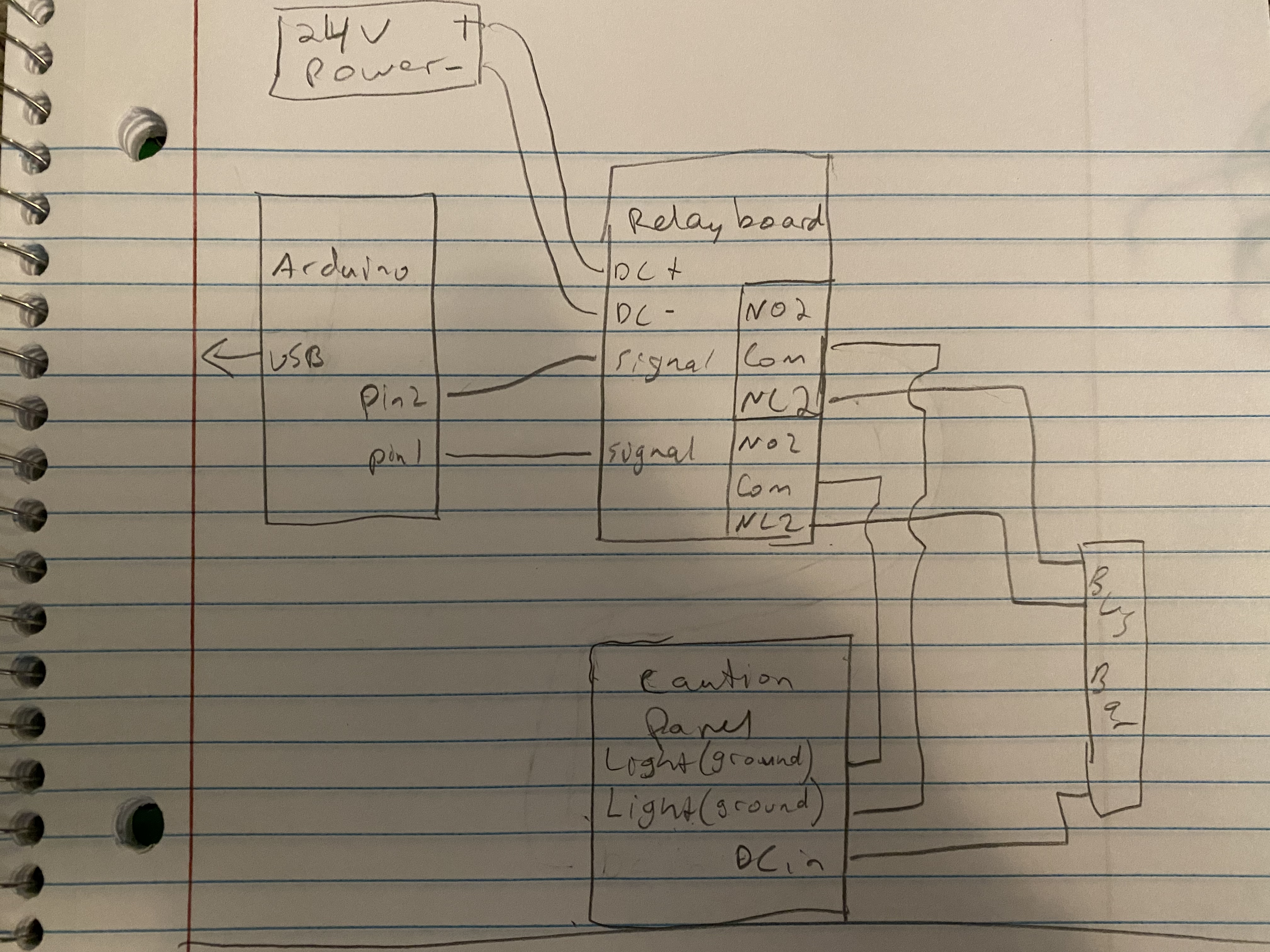
Ok so I got a relay board in. This picture is how I connected it to test. The question mark is what I can’t figure out. I tried every way I could think of but I can’t get the light to trigger. The arduino triggers the relay properly and I can hear the relay clicking whenever the correct light in dcs illuminates. To be clear the physical caution light illuminates when I have DC+ connected to the input and dc- connected to the pin that is specific to the light. I don’t know if DC- is the same as a ground connection? Maybe you can elaborate on that? MAJOR EDIT: I got the whole thing to work! I sat back and realized the relay is just a switch. I wired it up splitting the DC+ into the relay board inputs as well as direct into the caution panel, and sending the DC- into the relay board as well. Then I wired the caution panel pin for the specific light to the Normally open side of the relay, then the COM side back to the DC- of the power supply. I'll upload a diagram shortly if anyone is curious.
-
Exporting and driving a caution panel for the huey
Studsmcgee replied to Studsmcgee's topic in Home Cockpits
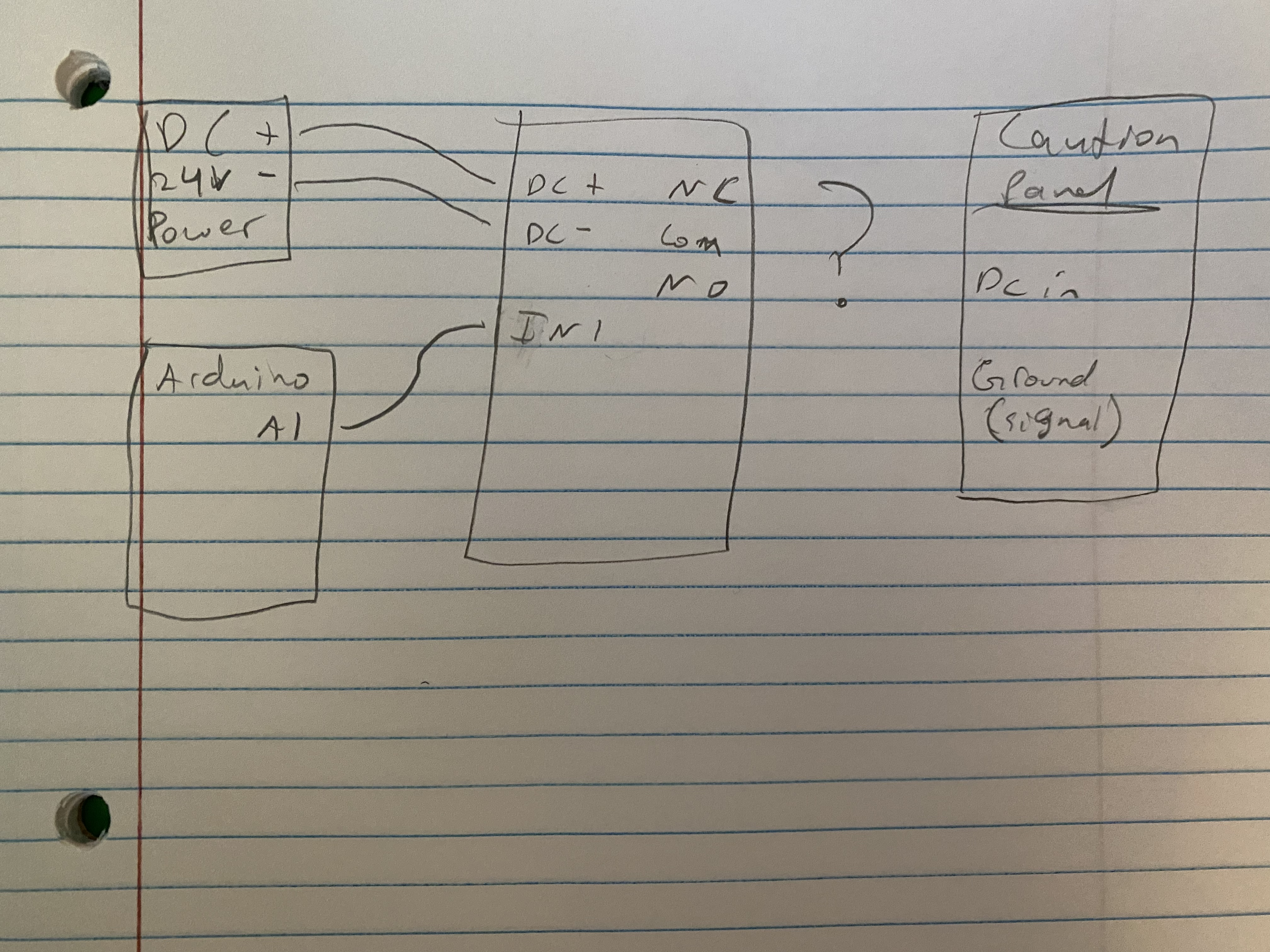
Ok I see what you meant about polarity with lights 2,3,10. The relay board looks like it would work. If I understand correctly all it needs is dc input, then a 1 wire signal from the arduino into the board. And then connect the panel lights to the relay side? Does that sound right? Additionally, I only have 1 24v power supply. It has plenty of amps to drive everything but how can I run power to all three boards from one plug? In the same vein, the caution panel has one input for power. But each relay seems to need an input and output? Maybe I’m not understanding correctly but how would this all work together? Would I only need 1 wire from the caution panel into each relay? Here’s a quick drawing of what I was thinking. Not sure if it’s even close but I’m trying to figure out how to power all the relays but have only 1 power supply and 1 DC input to the caution panel. Still haven’t figured how to expand this to include three boards.
-
Exporting and driving a caution panel for the huey
Studsmcgee replied to Studsmcgee's topic in Home Cockpits
That looks like exactly what I'd need. Can you expand a little more on what you mean by those inputs need to go to + ? Do you mean positive? I apologize my electronic circuit diagram skills are mostly non existent. I tried setting up a test with a mosfet I have but I don't think I got the wiring right. Any chance you might be able to explain what needs to be connected to what? Again I really appreciate the help. -
Exporting and driving a caution panel for the huey
Studsmcgee replied to Studsmcgee's topic in Home Cockpits
UPDATE: I've acquired the proper connector and I've confirmed No1sonuk is correct. Grounding the pin associated with the caution light while applying 28 (in my case 24) volts makes the light illuminate. Now it's just a question of making the DCS BIOS code work and then finding an arduino and a mosfet board with enough outputs to make all the lights work.
-
Exporting and driving a caution panel for the huey
Studsmcgee replied to Studsmcgee's topic in Home Cockpits
Thanks EvilBert. That makes a little more sense to me. I know you have quite the huey cockpit build. Were you able to get the caution panel working with DCS? If so I'm curious as to what hardware you used. -
Exporting and driving a caution panel for the huey
Studsmcgee replied to Studsmcgee's topic in Home Cockpits
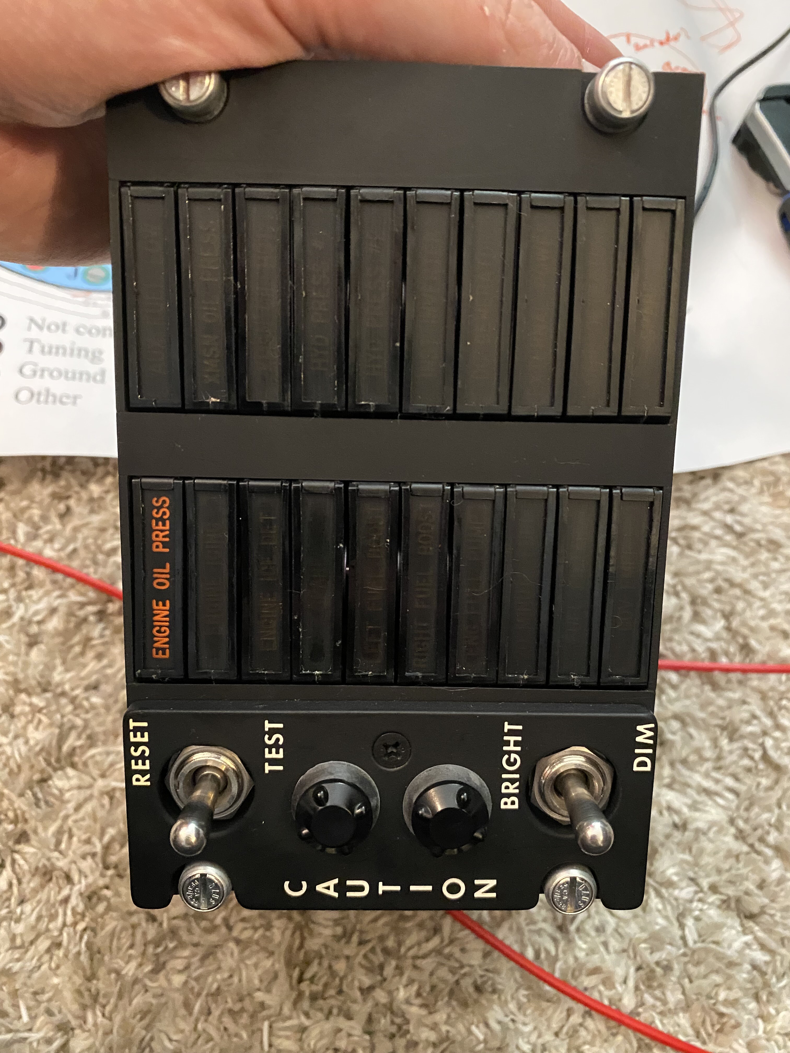
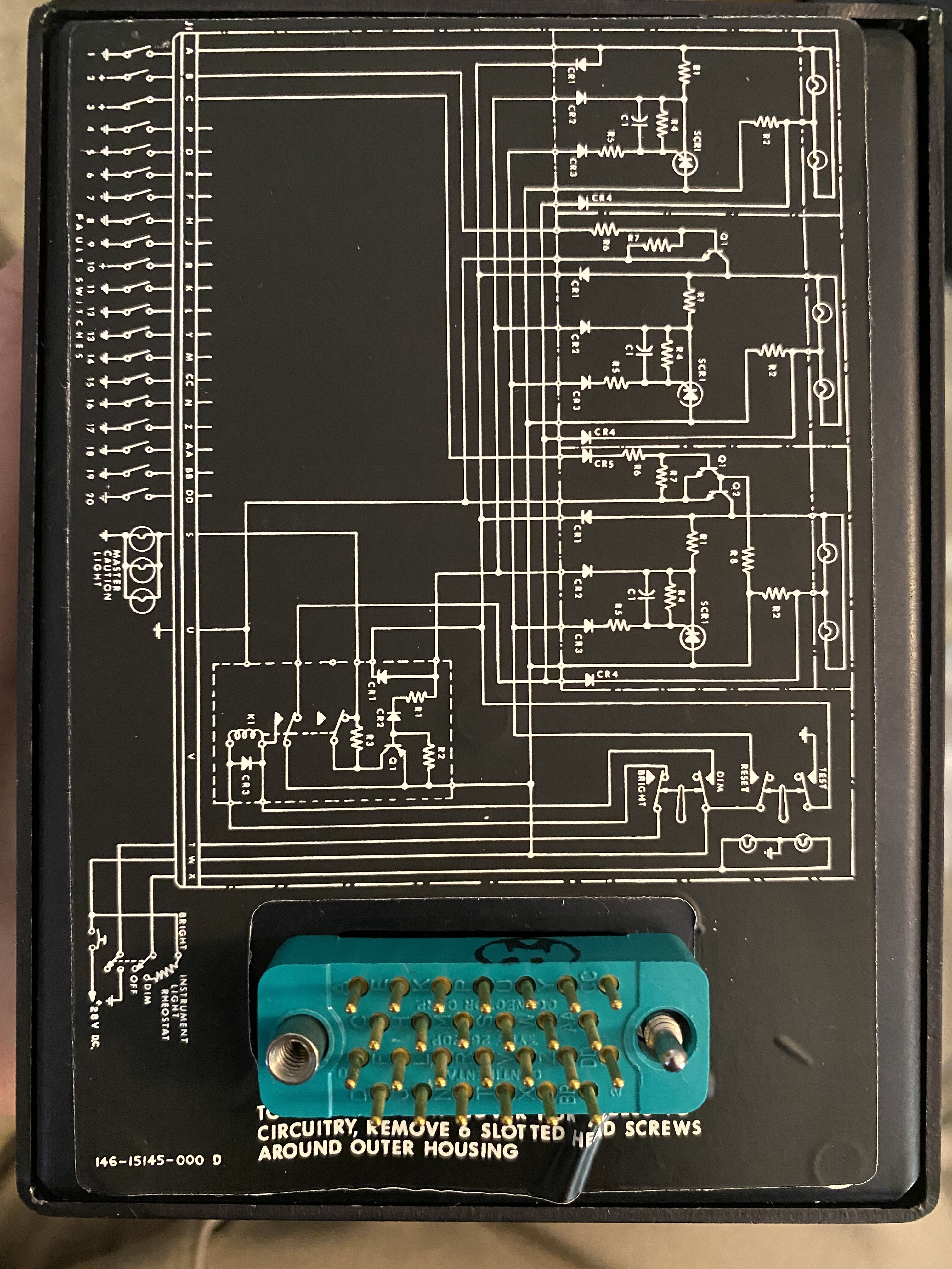
Well clearly I'm blind. the part number is a Continental 26-20P. I found one on ebay. And if you mean the purpose of the lights there are 20 indicators for caution/warning conditions. Low oil pressure, trans temp, things like that. Do you think a 24volt power supply would run it assuming I can figure the wiring out? Those seem easier to find than a 28 volt power supply. -
Exporting and driving a caution panel for the huey
Studsmcgee replied to Studsmcgee's topic in Home Cockpits
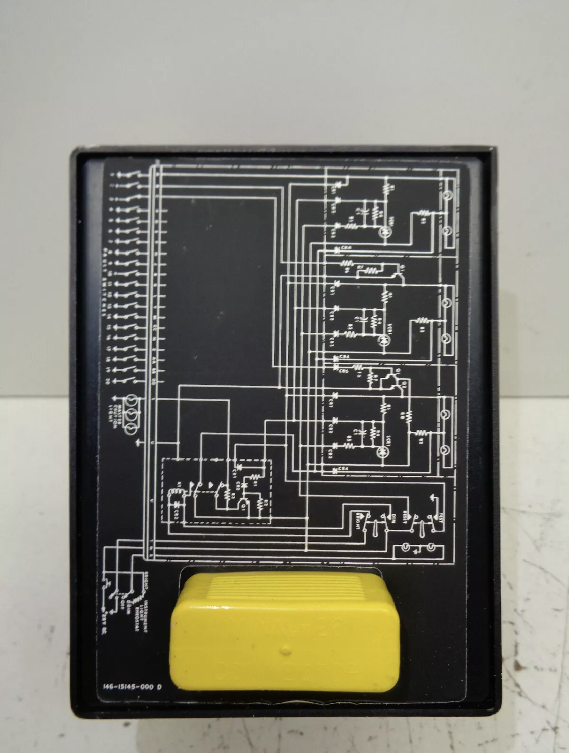
Here’s a better picture. I’m still at a loss as to what connector is on there. Something with 26 pins.
-
Exporting and driving a caution panel for the huey
Studsmcgee replied to Studsmcgee's topic in Home Cockpits
Ok. I’ll get a better picture of the diagram and the connector soon. If you get a chance could you possibly have a name or a link of what kind of mosfet I’d need? I Google searched a bit and there’s a lot of options and I want to make sure I have the correct one before I go and buy 20 of them or something. Thanks again for the help. -
Exporting and driving a caution panel for the huey
Studsmcgee replied to Studsmcgee's topic in Home Cockpits
Man Are you an electrical engineer? How’d you figure that out? I’m impressed haha. I’ll have to play with it more soon. I’m looking for a connector but no luck. In this case would I need a mosfet channel for each light? And then program the arduino to switch the mosfet to ground when the caution light in game is on? (I’m a novice when it comes to circuits like this). -
Exporting and driving a caution panel for the huey
Studsmcgee replied to Studsmcgee's topic in Home Cockpits
I did open it up. And it seems like there’s individual lamps. Probably two bulbs per cell. There’s a schematic on the back but I’m not sure exactly what it’s telling me. I also haven’t found the connector that would work with in. I can post a picture later. What kind of mosfet would I use? And can that connect to dcs or would I need an arduino in between or something. ?
-
So I’ve stumbled into making more panels for my Huey cockpit. I’ve acquired an original caution light panel and I’m hoping to incorporate it into the build and make it work with dcs. First off I’ve done lots of switch panel builds. But I’ve never messed with getting data OUT of dcs to drive physical devices. What do I need to export the caution light data? Also any advice on what kind of circuit I’d need to power leds or lights? I’ve head about using an led matrix and an arduino but I’m clueless at how that works. I’m not above disassembling the panel (I think I’ll have to as it was designed for 28volt DC power). I’d appreciate any general or specific advise on how to go about this. Thanks!