Studsmcgee
-
Posts
50 -
Joined
-
Last visited
Content Type
Profiles
Forums
Events
Everything posted by Studsmcgee
-
Exporting and driving a caution panel for the huey
Studsmcgee replied to Studsmcgee's topic in Home Cockpits
Once I realized the board doesn’t pass the power through to the relay it finally clicked for me. I still need to solder all the wires to the connector to test each light and then find a way to get at least the test and reset switches working. I’m not too worried about the bright dim switch. I don’t think I’ve ever used it in game. Also No1sonuk I really appreciate the help! Thanks again. -
Exporting and driving a caution panel for the huey
Studsmcgee replied to Studsmcgee's topic in Home Cockpits
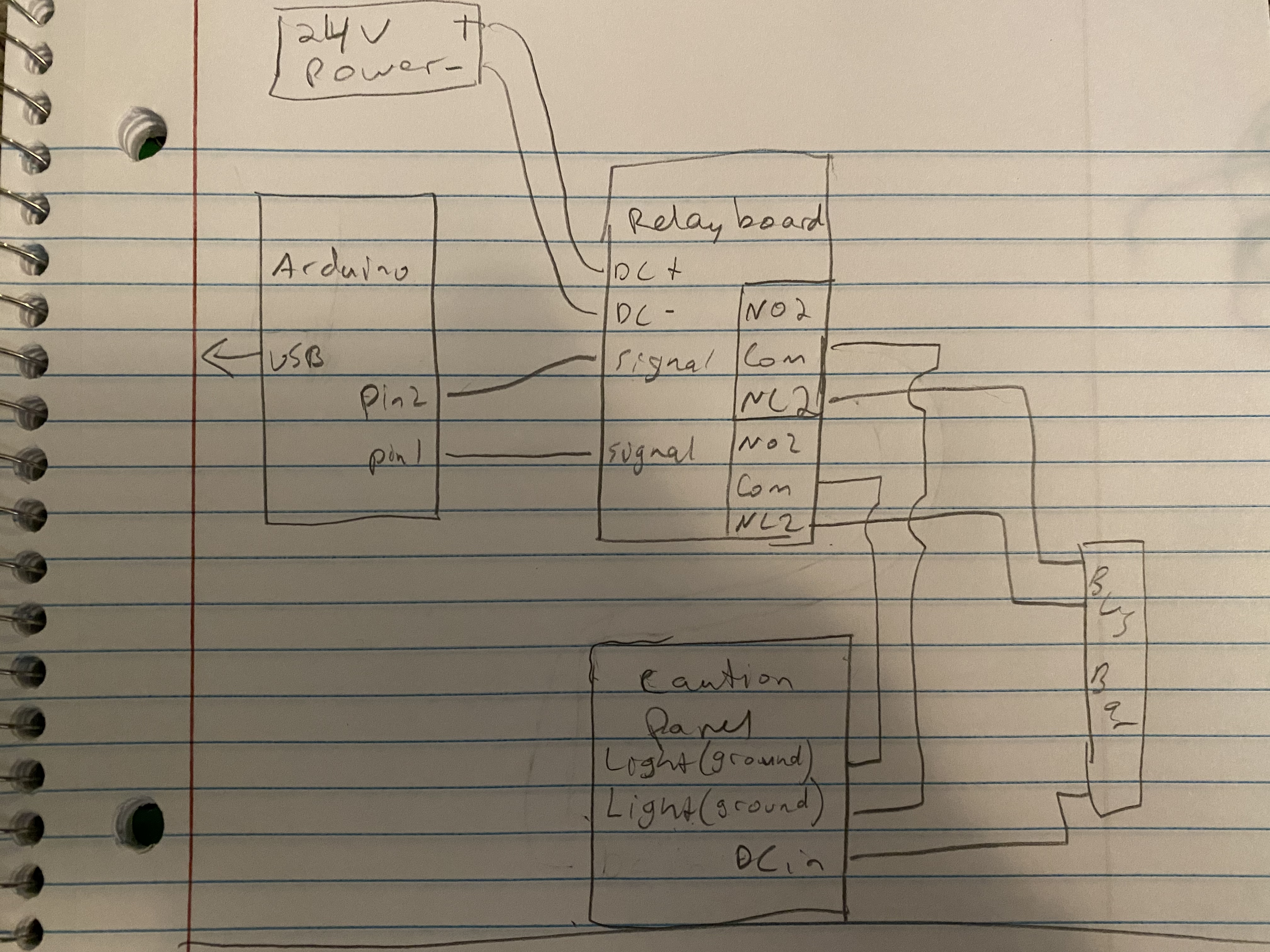
Ok so I got a relay board in. This picture is how I connected it to test. The question mark is what I can’t figure out. I tried every way I could think of but I can’t get the light to trigger. The arduino triggers the relay properly and I can hear the relay clicking whenever the correct light in dcs illuminates. To be clear the physical caution light illuminates when I have DC+ connected to the input and dc- connected to the pin that is specific to the light. I don’t know if DC- is the same as a ground connection? Maybe you can elaborate on that? MAJOR EDIT: I got the whole thing to work! I sat back and realized the relay is just a switch. I wired it up splitting the DC+ into the relay board inputs as well as direct into the caution panel, and sending the DC- into the relay board as well. Then I wired the caution panel pin for the specific light to the Normally open side of the relay, then the COM side back to the DC- of the power supply. I'll upload a diagram shortly if anyone is curious.
-
Exporting and driving a caution panel for the huey
Studsmcgee replied to Studsmcgee's topic in Home Cockpits
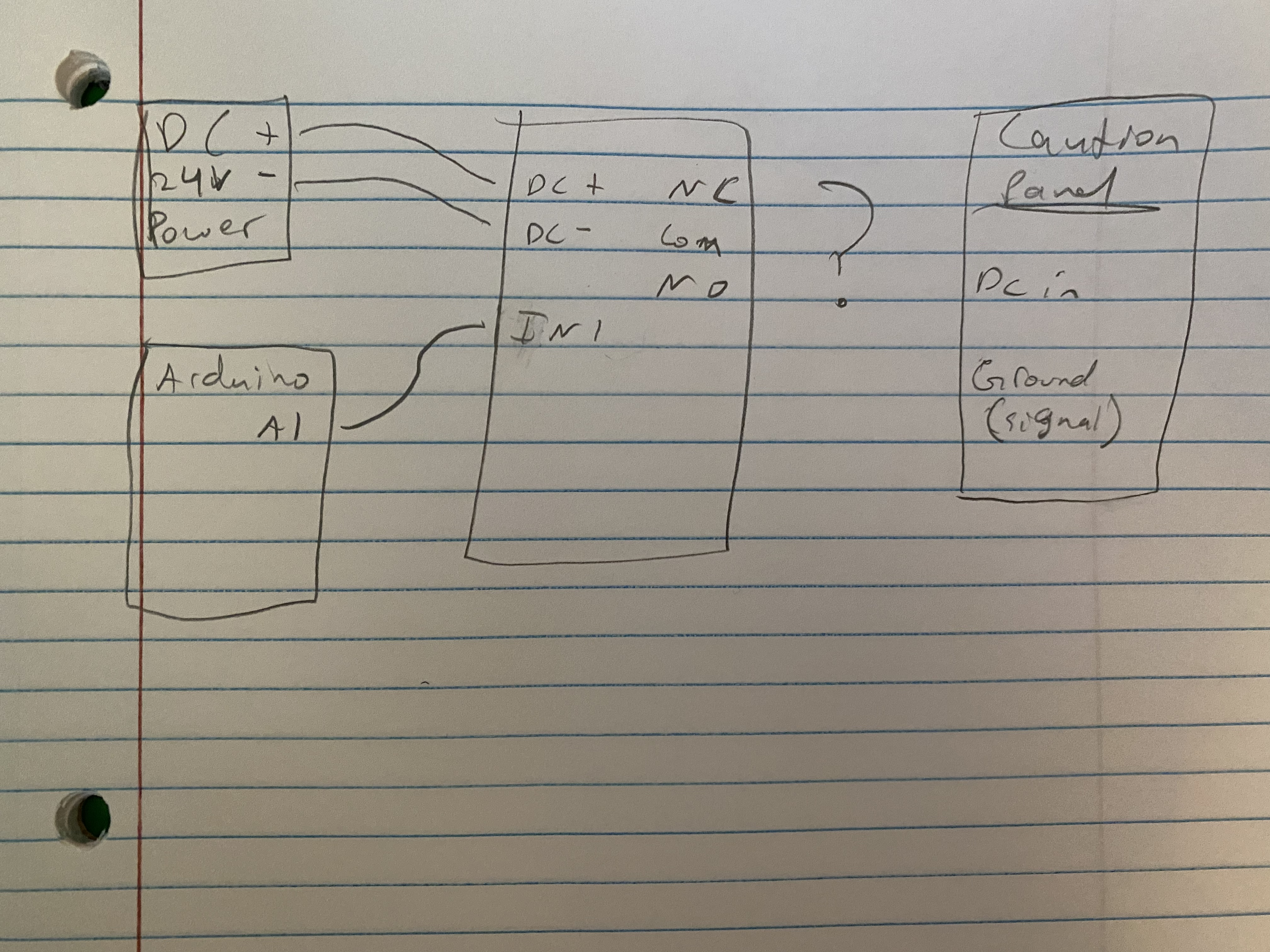
Ok I see what you meant about polarity with lights 2,3,10. The relay board looks like it would work. If I understand correctly all it needs is dc input, then a 1 wire signal from the arduino into the board. And then connect the panel lights to the relay side? Does that sound right? Additionally, I only have 1 24v power supply. It has plenty of amps to drive everything but how can I run power to all three boards from one plug? In the same vein, the caution panel has one input for power. But each relay seems to need an input and output? Maybe I’m not understanding correctly but how would this all work together? Would I only need 1 wire from the caution panel into each relay? Here’s a quick drawing of what I was thinking. Not sure if it’s even close but I’m trying to figure out how to power all the relays but have only 1 power supply and 1 DC input to the caution panel. Still haven’t figured how to expand this to include three boards.
-
Exporting and driving a caution panel for the huey
Studsmcgee replied to Studsmcgee's topic in Home Cockpits
That looks like exactly what I'd need. Can you expand a little more on what you mean by those inputs need to go to + ? Do you mean positive? I apologize my electronic circuit diagram skills are mostly non existent. I tried setting up a test with a mosfet I have but I don't think I got the wiring right. Any chance you might be able to explain what needs to be connected to what? Again I really appreciate the help. -
Exporting and driving a caution panel for the huey
Studsmcgee replied to Studsmcgee's topic in Home Cockpits
UPDATE: I've acquired the proper connector and I've confirmed No1sonuk is correct. Grounding the pin associated with the caution light while applying 28 (in my case 24) volts makes the light illuminate. Now it's just a question of making the DCS BIOS code work and then finding an arduino and a mosfet board with enough outputs to make all the lights work.
-
Exporting and driving a caution panel for the huey
Studsmcgee replied to Studsmcgee's topic in Home Cockpits
Thanks EvilBert. That makes a little more sense to me. I know you have quite the huey cockpit build. Were you able to get the caution panel working with DCS? If so I'm curious as to what hardware you used. -
Exporting and driving a caution panel for the huey
Studsmcgee replied to Studsmcgee's topic in Home Cockpits
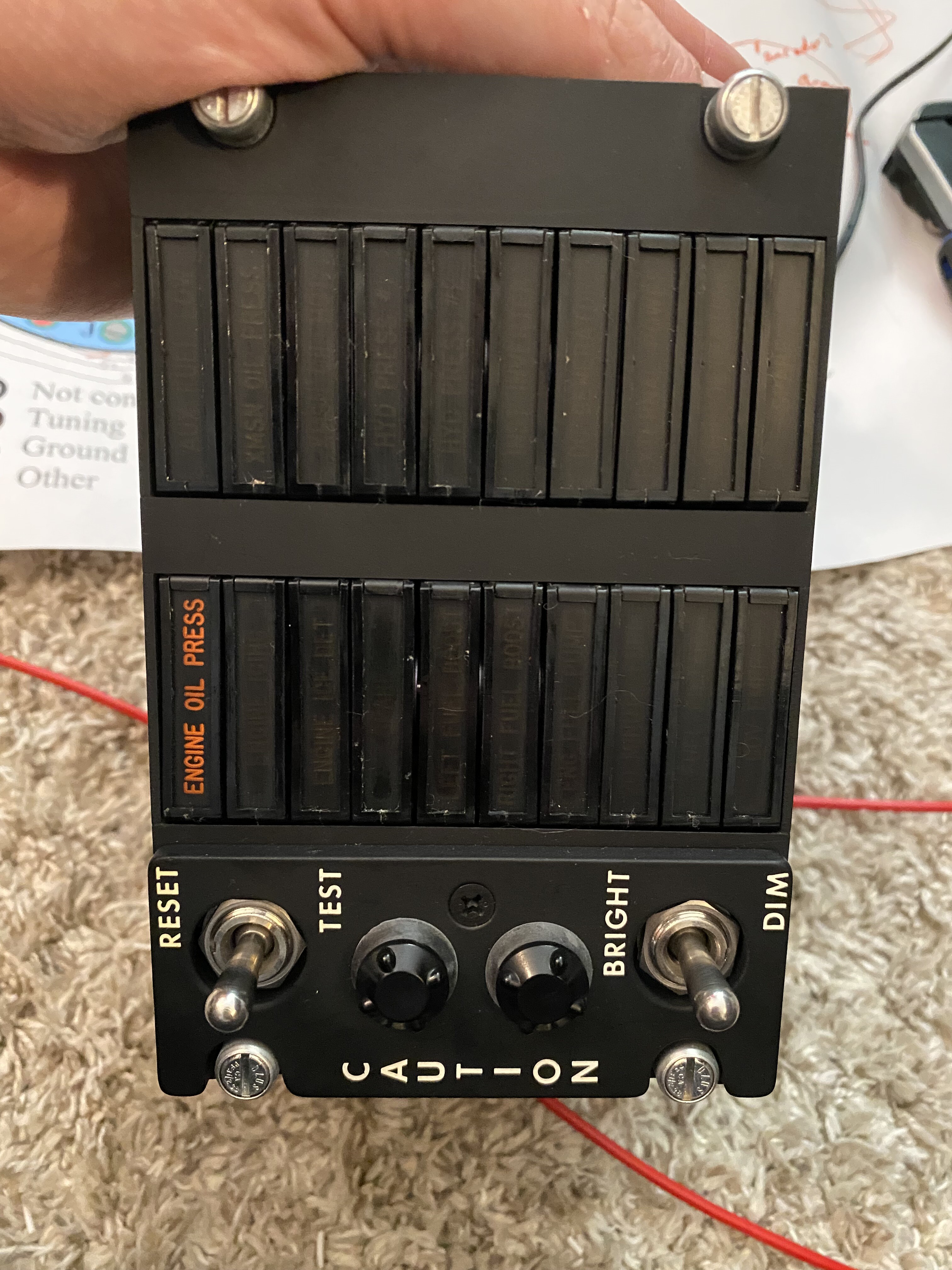
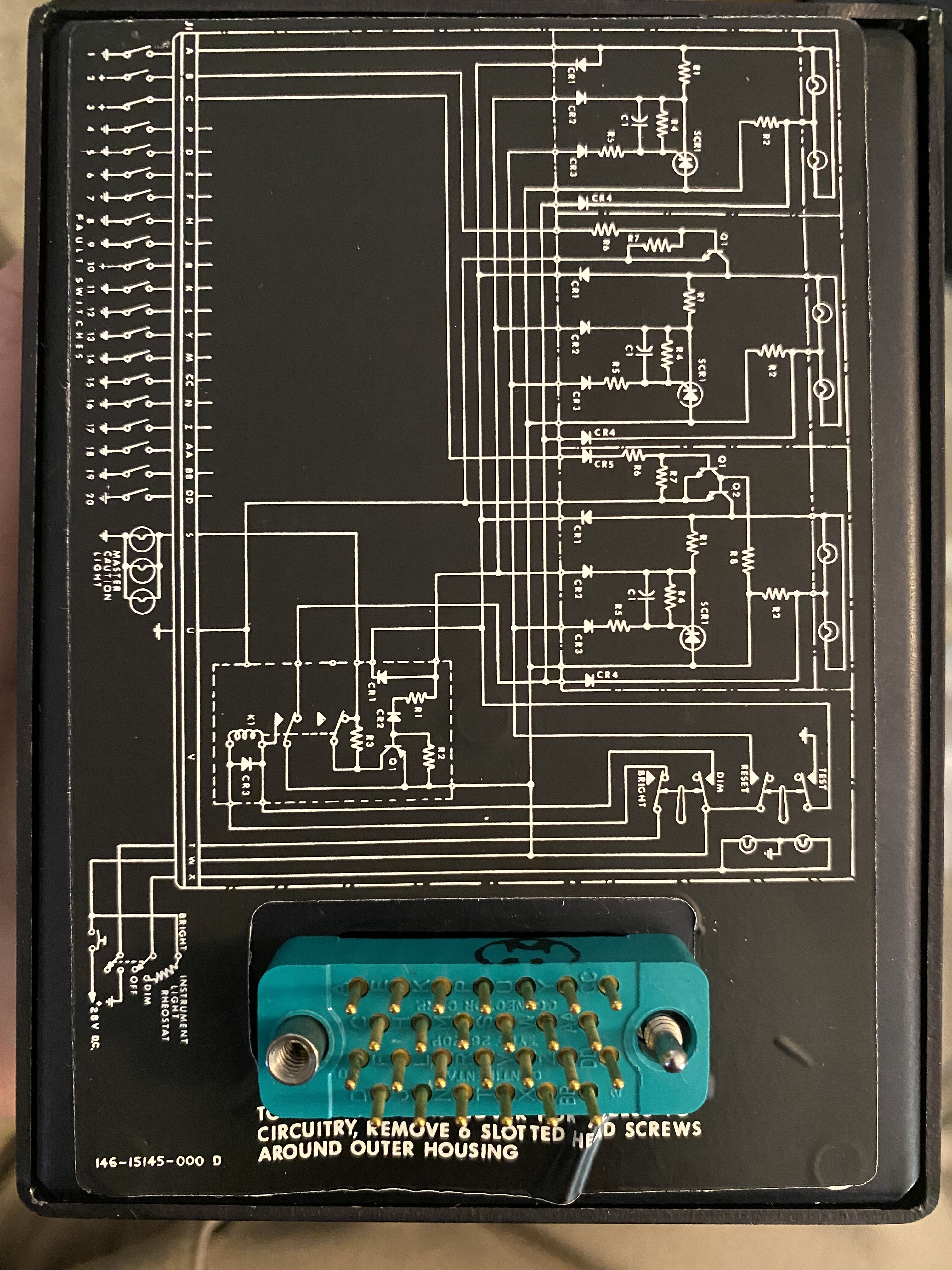
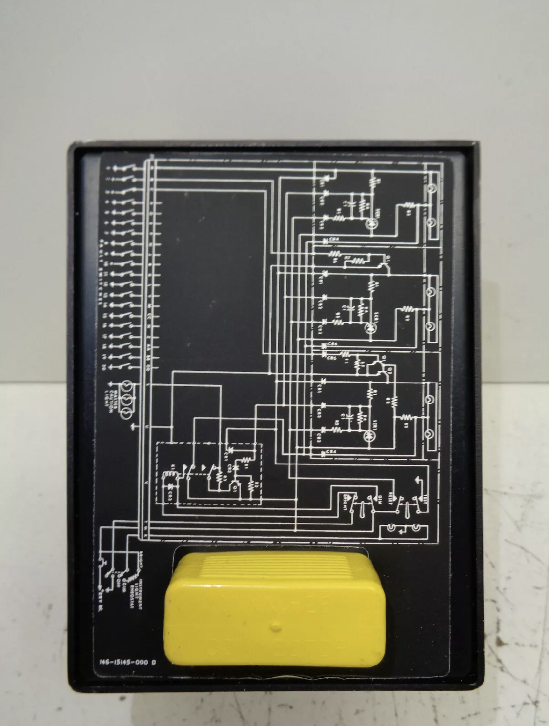
Well clearly I'm blind. the part number is a Continental 26-20P. I found one on ebay. And if you mean the purpose of the lights there are 20 indicators for caution/warning conditions. Low oil pressure, trans temp, things like that. Do you think a 24volt power supply would run it assuming I can figure the wiring out? Those seem easier to find than a 28 volt power supply. -
Exporting and driving a caution panel for the huey
Studsmcgee replied to Studsmcgee's topic in Home Cockpits
Here’s a better picture. I’m still at a loss as to what connector is on there. Something with 26 pins.
-
Exporting and driving a caution panel for the huey
Studsmcgee replied to Studsmcgee's topic in Home Cockpits
Ok. I’ll get a better picture of the diagram and the connector soon. If you get a chance could you possibly have a name or a link of what kind of mosfet I’d need? I Google searched a bit and there’s a lot of options and I want to make sure I have the correct one before I go and buy 20 of them or something. Thanks again for the help. -
Exporting and driving a caution panel for the huey
Studsmcgee replied to Studsmcgee's topic in Home Cockpits
Man Are you an electrical engineer? How’d you figure that out? I’m impressed haha. I’ll have to play with it more soon. I’m looking for a connector but no luck. In this case would I need a mosfet channel for each light? And then program the arduino to switch the mosfet to ground when the caution light in game is on? (I’m a novice when it comes to circuits like this). -
Exporting and driving a caution panel for the huey
Studsmcgee replied to Studsmcgee's topic in Home Cockpits
I did open it up. And it seems like there’s individual lamps. Probably two bulbs per cell. There’s a schematic on the back but I’m not sure exactly what it’s telling me. I also haven’t found the connector that would work with in. I can post a picture later. What kind of mosfet would I use? And can that connect to dcs or would I need an arduino in between or something. ?
-
So I’ve stumbled into making more panels for my Huey cockpit. I’ve acquired an original caution light panel and I’m hoping to incorporate it into the build and make it work with dcs. First off I’ve done lots of switch panel builds. But I’ve never messed with getting data OUT of dcs to drive physical devices. What do I need to export the caution light data? Also any advice on what kind of circuit I’d need to power leds or lights? I’ve head about using an led matrix and an arduino but I’m clueless at how that works. I’m not above disassembling the panel (I think I’ll have to as it was designed for 28volt DC power). I’d appreciate any general or specific advise on how to go about this. Thanks!
-
It’s starting to become an addiction. I’m checking eBay all the time. My next project is a radio stack with mostly original radio control heads. No idea if it’ll work but im going to try haha.
-
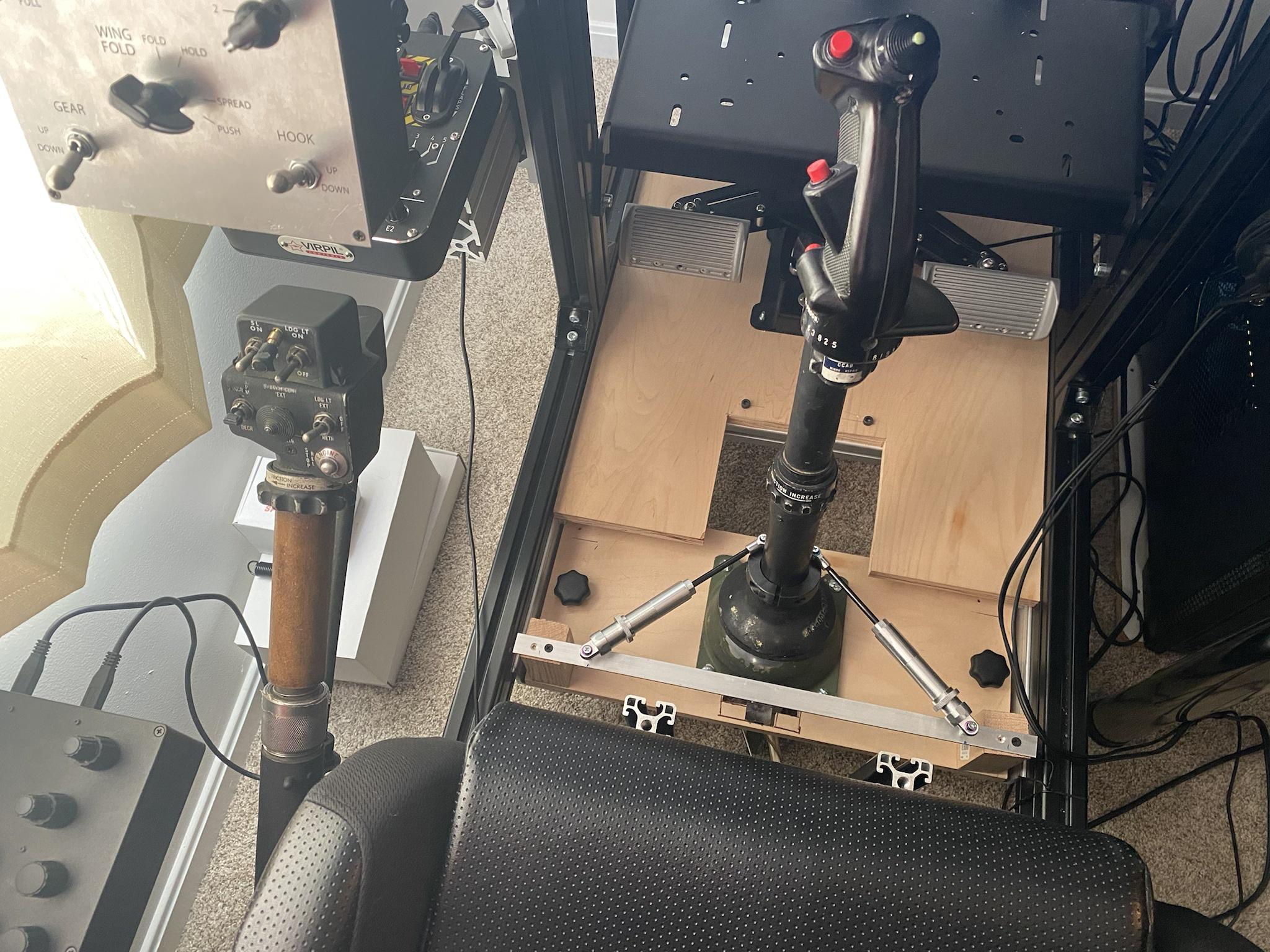
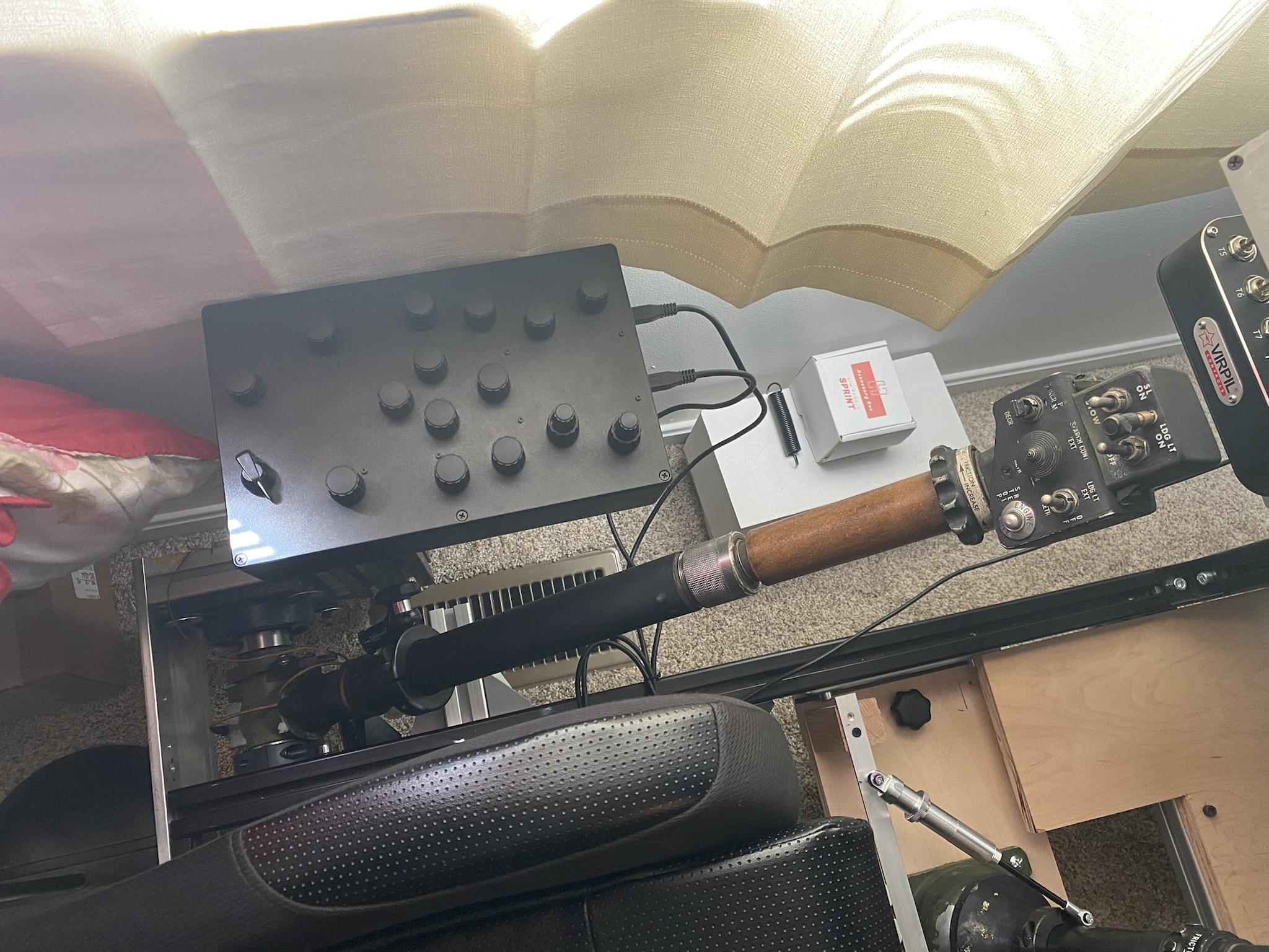
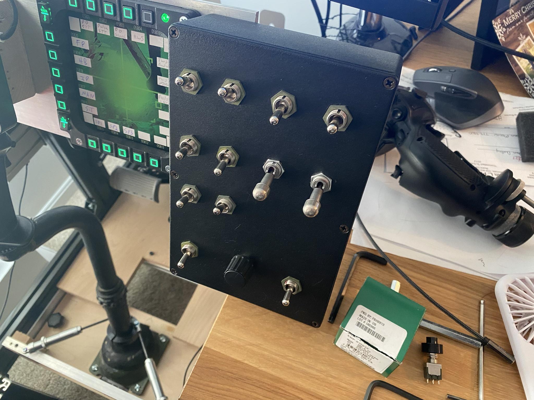
Here is what I'm using. Definitely went overkill for this one but I can't say no to new projects and the huey is still my favorite thing to fly in dcs. Cyclic and collective are the real thing from the aircraft. Buttons are all wired up and working as well as the axis for everything including the twist throttle. Had to edit the default.lua file to make some of the switches behave correctly and now I can go from cold start to flying without touching the keyboard (except for closing the doors) There is also a custom radio box and systems control box. the smaller one needs labels but the radio box is soon gettin replaced with some custom panels to include a real UHF control head that I hope to make work in the sim. The whole set up makes flying the huey a dream! Probably the closest I'll get to flying the real thing.
-
Thanks! I used the built in friction a little but mine is rather sticky. Have you used any grease or lubricant on the mechanism? It also seems to be stiffer near the edge of the travel and looser near the center.
-
I've been asking a few questions about converting real huey controls for use with DCS. I figured I'd share a few images of what I have so far. Big thanks to yogi149 and EvilBert VR. If you guys see this thanks for answering all my questions! Cyclic and Collective are the real deal. All axis and buttons are working (except landing light retract, that is eluding me at the moment) There is no physical idle stop on the throttle for now, but I faked it in the software using joystick gremlin to make virtual buttons at the bottom of the throttle axis. I had to remake the collective mount as mine didn't come with an original. Huge 40mm bearing from amazon and a shaft collar from McMaster Carr did the trick. Motorcycle steering damper helps smooth out the movement. The damper can be detached with a threaded knob and then the whole collective can be flipped up behind my shoulder to allow room for my Virpil throttle to slide into place. Everything is done with hall effect sensors and two small magnets. Seems pretty precise so far. However I'm looking to add some friction or damping to the cyclic as its currently just free floating. Better than fighting springs but holding the weight of the stick gets tiring. That's what I have so far. Up next is to clean up all the wiring and mount the Bodnar board in an enclosure. Also going to make a huey specific button box at some point. The goal is to do a full start up without touching the keyboard or mouse. Thanks for looking!
-
That worked great! Thanks. Do you have any sort of spring force or dampening on your cyclic? Mine is currently completely free moving. Easy to hover with but it’s tiring holding the weight of the stick constantly. Any thoughts on that?
-
Hey thank you for the photos! Are the 3D printed parts just glued to the gimbal? Or did you drill and tap for screws somewhere?
-
Huey cyclic and Hall effect sensor mounting.
Studsmcgee replied to Studsmcgee's topic in Home Cockpits
Hello! I did in fact see your build which is amazing by the way. Any chance you have any more info on how you attached the hall sensors to the cyclic? I see the one picture with your 3D printed parts but I can't see how they're attached to the gimbal. Do you have any other pictures or diagrams? If so I'd greatly appreciate it or any other advice you have about making the controls work in DCS. Thanks! -
So I'm working on building out huey controls for my cockpit. At present I have the buttons working on the cyclic and the collective. Up next is making the axes work. I have a Leo Bodnar board and some hall sensors and magnets. I've done a little research and I believe I want this set up for the magnets and sensors: https://imgur.com/8xpEhZ6 The issue is I don't know how to mount that set up on the cyclic gimbal. Here is an image of that: https://imgur.com/7Uojtyd If anyone has any ideas on how to attach everything I'd really appreciate it. Also what is the proper way to wire up the hall sensors? I was going to solder wires to them but the leads seem pretty fragile and I'm afraid the heat might damage the sensor. What do you guys do? Thanks!
-
Sorry for asking something probably obvious, but in the last mission I think there is supposed to be What radio settings do I need? I have the select panel set to 2 so I can transmit to the wingman. Is that right? Or does the sound track play somewhere else?
-
I'm starting to wonder if I have the wrong kind of mosfet board For me the readings are. Black lead on V- and red lead on GND = 15.5 M ohms Read lead on V- and black lead on GND = 0L Seems way off from yours, any ideas?
-
Ok so this is interesting. If I disconnect the arduino and only have the 12v and solenoid hooked up the solenoid actuates when the 12v is applied. Does that indicate a faulty mosfet? I tried the next step just incase and the 5v from the arduino applied to the signal input of the mosfet lights up the mosfet led but does not affect the solenoid.
-
Alright, so I tried another MOSFET board, same result. I wired the 12v input with the - side as ground and the + side as VIN. Is that correct? If it is then I don't know what else I'm missing. Maybe its still code related?
-
Appreciate the tip. I tried your code example and it does indeed light up the led. When I have 12v connected to the MOSFET the solenoid actuates and stays on regardless of the button position. I removed the VCC connection and got the same result. I just don't know what I need to tell the MOSFET to switch the 12v power on and off. I wish I knew more about the code so I could try more things.