
Pavespawn
-
Posts
107 -
Joined
-
Last visited
Content Type
Profiles
Forums
Events
Everything posted by Pavespawn
-
Based on that I changed my code to the following but I still get nothing to register. I wanted to make sure that my pins were still connected so as an experiment I uploaded a test sketch that defined tacan10 as SwitchMultiPos in order to see if it would give me a return and it does. I must have something else wrong or missing that is preventing the sketch from seeing the values. :( Here is my updated sketch based on your inputs. I must be missing something. #define DCSBIOS_IRQ_SERIAL #include "DcsBios.h" int Tacan_left_ingame; // hold value from DCS /* paste code snippets from the reference documentation here */ const byte tacanModePins[5] = {9, 10, 11, 12, 13}; DcsBios::SwitchMultiPos tacanMode("TACAN_MODE", tacanModePins, 5); DcsBios::Switch2Pos tacanXy("TACAN_XY", 7); DcsBios::Potentiometer tacanVol("TACAN_VOL", A0); DcsBios::Switch2Pos tacanTestBtn("TACAN_TEST_BTN", 6); //TACAN Left Channel void onTacan10Change(unsigned int newValue_Tacan_left) { Tacan_left_ingame = newValue_Tacan_left; } DcsBios::IntegerBuffer tacan10Buffer(0x1158, 0x0f00, 8, onTacan10Change); void setup() { DcsBios::setup(); //TACAN_10 inputs DDRA = B00000000; // set PINA (digital 29-22) as inputs PORTA = B11111111; // Sets (digital 29-22) with internal pull up //TACAN_10 inputs continued DDRC = B00000000; // set PINA (digital 30-37) as inputs PORTC = B11111111; // Sets (digital 30-37) with internal pull up } int inputTacan_left() { int valueTacan_left; if (PINA == B11111110) { valueTacan_left = 0; } if (PINA == B11111101) { valueTacan_left = 1; } if (PINA == B11111011) { valueTacan_left = 2; } if (PINA == B11110111) { valueTacan_left = 3; } if (PINA == B11101111) { valueTacan_left = 4; } if (PINA == B11011111) { valueTacan_left = 5; } if (PINA == B10111111) { valueTacan_left = 6; } if (PINA == B01111111) { valueTacan_left = 7; } if (PINC == B11101111) { valueTacan_left = 8; } if (PINC == B11110111) { valueTacan_left = 9; } if (PINC == B11111011) { valueTacan_left = 10; } if (PINC == B11111101) { valueTacan_left = 11; } if (PINA == B11111110) { valueTacan_left = 12; } return valueTacan_left; } void loop() { DcsBios::loop(); } void setTacan() { if (Tacan_left_ingame < inputTacan_left()) { sendDcsBiosMessage("TACAN_10", "INC"); } if (Tacan_left_ingame > inputTacan_left()) { sendDcsBiosMessage("TACAN_10", "DEC"); } }
-
Here is the code I have loaded. I do not get any indication that the left channel selector is even being recognized. Unlike the other switches, I get no flicker of a Tx light on the board and neither the serial monitor or the connect-serial-port cmd show activity (used separately) #define DCSBIOS_IRQ_SERIAL #include "DcsBios.h" int Tacan_left_ingame; // hold value from DCS /* paste code snippets from the reference documentation here */ const byte tacanModePins[5] = {9, 10, 11, 12, 13}; DcsBios::SwitchMultiPos tacanMode("TACAN_MODE", tacanModePins, 5); DcsBios::Switch2Pos tacanXy("TACAN_XY", 7); DcsBios::Potentiometer tacanVol("TACAN_VOL", A0); DcsBios::Switch2Pos tacanTestBtn("TACAN_TEST_BTN", 6); //TACAN Left Channel void onTacan10Change(unsigned int newValue_Tacan_left) { Tacan_left_ingame = newValue_Tacan_left; } DcsBios::IntegerBuffer tacan10Buffer(0x1158, 0x0f00, 8, onTacan10Change); void setup() { DcsBios::setup(); //TACAN_10 inputs DDRA = B00000000; // set PINA (digital 29-22) as inputs PORTA = B11111111; // Sets (digital 29-22) with internal pull up //TACAN_10 inputs continued DDRC = B00000000; // set PINA (digital 30-37) as inputs PORTC = B11111111; // Sets (digital 30-37) with internal pull up } int inputTacan_left() { int valueTacan_left; if (PINA == B10000000) { valueTacan_left = 0; } if (PINA == B01000000) { valueTacan_left = 1; } if (PINA == B00100000) { valueTacan_left = 2; } if (PINA == B00010000) { valueTacan_left = 3; } if (PINA == B00001000) { valueTacan_left = 4; } if (PINA == B00000100) { valueTacan_left = 5; } if (PINA == B00000010) { valueTacan_left = 6; } if (PINA == B00000001) { valueTacan_left = 7; } if (PINC == B10000000) { valueTacan_left = 8; } if (PINC == B01000000) { valueTacan_left = 9; } if (PINC == B00100000) { valueTacan_left = 10; } if (PINC == B00010000) { valueTacan_left = 11; } if (PINA == B00001000) { valueTacan_left = 12; } return valueTacan_left; } void loop() { DcsBios::loop(); } void setTacan() { if (Tacan_left_ingame < inputTacan_left()) { sendDcsBiosMessage("TACAN_10", "INC"); } if (Tacan_left_ingame > inputTacan_left()) { sendDcsBiosMessage("TACAN_10", "DEC"); } }
-
Ok here is the matrix I created even though it seemed too simple since I modded the rotary to allow a single contact each turn of the dial. What I have depicted is: Across the top is the rotary positions and the pin that the corresponding wire goes into the Mega. The left side shows the channel that shows when in the contacted position. If I understand this correctly then the code for channel 0 would be B10000000. The matrix runs to position 8 (channel 7) then it would have to start over on the next set of registers so I would start over (channel 8 on pin 30 would also code to B10000000.
-
Hans, Thanks for providing so much assistance and feedback. I did start with modding the switch so there is only a single contact for each rotation. I originally hoped that I could define the channel selector as a rotary switch and then it would work all the way to 12 ( remember you saying that you had an issue with that) but that did not work. I really needed some kind of a win so I rigged up the encoder just to prove I could make the dial move. I don’t see this as the permanent fix. I am now wondering if I can stick with the individual contact idea for each switch but also use the port registers. I am going to try to code it like so (I am typing this at work so this is a guess): if (PINA == B10000000) { valueTacan_left = 0; } if (PINA == B01000000) { valueTacan_left = 1; } if (PINA == B00100000) { valueTacan_left = 2; } Etc, etc So that each individual contact works as a high reading. Since I have 13 contacts I will have to use multiple ports but it seems like it should work. What do you think? I started a diagram to map this out so I’ll finish that and post my product based on my modified switch. I’ll then move onto the right switch. Can you tell me what timer library you are using? I have one but it didn’t like some of your commands.
-
Thanks. I was using some of his code from that project!
-
Yup. All that is coded and works. What I mean is that because the dial is a physical one, if DCS starts and the physical dial is set to anything other than 0, it doesn't sync. DCS BIOS just knows to DEC or INC. It doesn't know where my physical dial is set at start.
-
Well I’m the absence of guidance, I went with the next best thing: I made things up. I prototyped a rotary encoder (fancy way of saying “I rigged this crap up”) to the output shaft of the left channel selector. It works but you have to make sure you are set to 0 at game start. Is there a way to get DCS to recognize where the encoder is positioned?
-
-
I was wondering if you can code the TACAN channel selectors as a rotary switch. It will take up more pins but I have a real TACAN and I have modded the rotary to allow for a single contact every rotation.
-
Also it seems I need a different photo hosting site since photobucket is ransoming my pictures.
-
Hans, I’ll have to get some of those sockets. I was concerned about the heat from my soldering. I’ll also start from scratch and try to get a master caution to work. The ground for my switches work when I have the Arduino in serial. Is there a different ground requirement when in RS485 mode? I would love for this to be the problem because I can fix that easy!!!
-
Here is my code: Master /* Tell DCS-BIOS this is a RS-485 Master. You will need to flash this to a Mega 2560. */ #define DCSBIOS_RS485_MASTER /* Define where the TX_ENABLE signals are connected. You can connect up to three half-duplex RS-485 transceivers. Arduino Pin RS-485 Transceiver Pin TXn ------------------- DI (driver input) RXn ------------------- RO (Receiver Output) UARTn_TXENABLE_PIN ---- /RE, DE (active low receiver enable, driver enable) If you have less than three transceivers connected, comment out the corresponding #define UARTn_TEXENABLE_PIN lines for receivers that are not present. */ #define UART1_TXENABLE_PIN 2 /*#define UART2_TXENABLE_PIN 3 #define UART3_TXENABLE_PIN 4 */ #include "DcsBios.h" void setup() { DcsBios::setup(); } void loop() { DcsBios::loop(); } Slave /* The following #define tells DCS-BIOS that this is a RS-485 slave device. It also sets the address of this slave device. The slave address should be between 1 and 126 and must be unique among all devices on the same bus. */ #define DCSBIOS_RS485_SLAVE 3 /* The Arduino pin that is connected to the /RE and DE pins on the RS-485 transceiver. */ #define TXENABLE_PIN 2 #include "DcsBios.h" /* paste code snippets from the reference documentation here */ DcsBios::Switch2Pos eppAcGenPwrL("EPP_AC_GEN_PWR_L", 10); DcsBios::Switch2Pos eppAcGenPwrR("EPP_AC_GEN_PWR_R", 9); DcsBios::Switch2Pos eppApuGenPwr("EPP_APU_GEN_PWR", 7); DcsBios::Switch2Pos eppBatteryPwr("EPP_BATTERY_PWR", A0); DcsBios::Switch2Pos eppEmerFlood("EPP_EMER_FLOOD", 5); DcsBios::Switch3Pos eppInverter("EPP_INVERTER", 6, 8); DcsBios::Switch3Pos canopyOpen("CANOPY_OPEN", A1, A2); void setup() { DcsBios::setup(); } void loop() { DcsBios::loop(); }
-
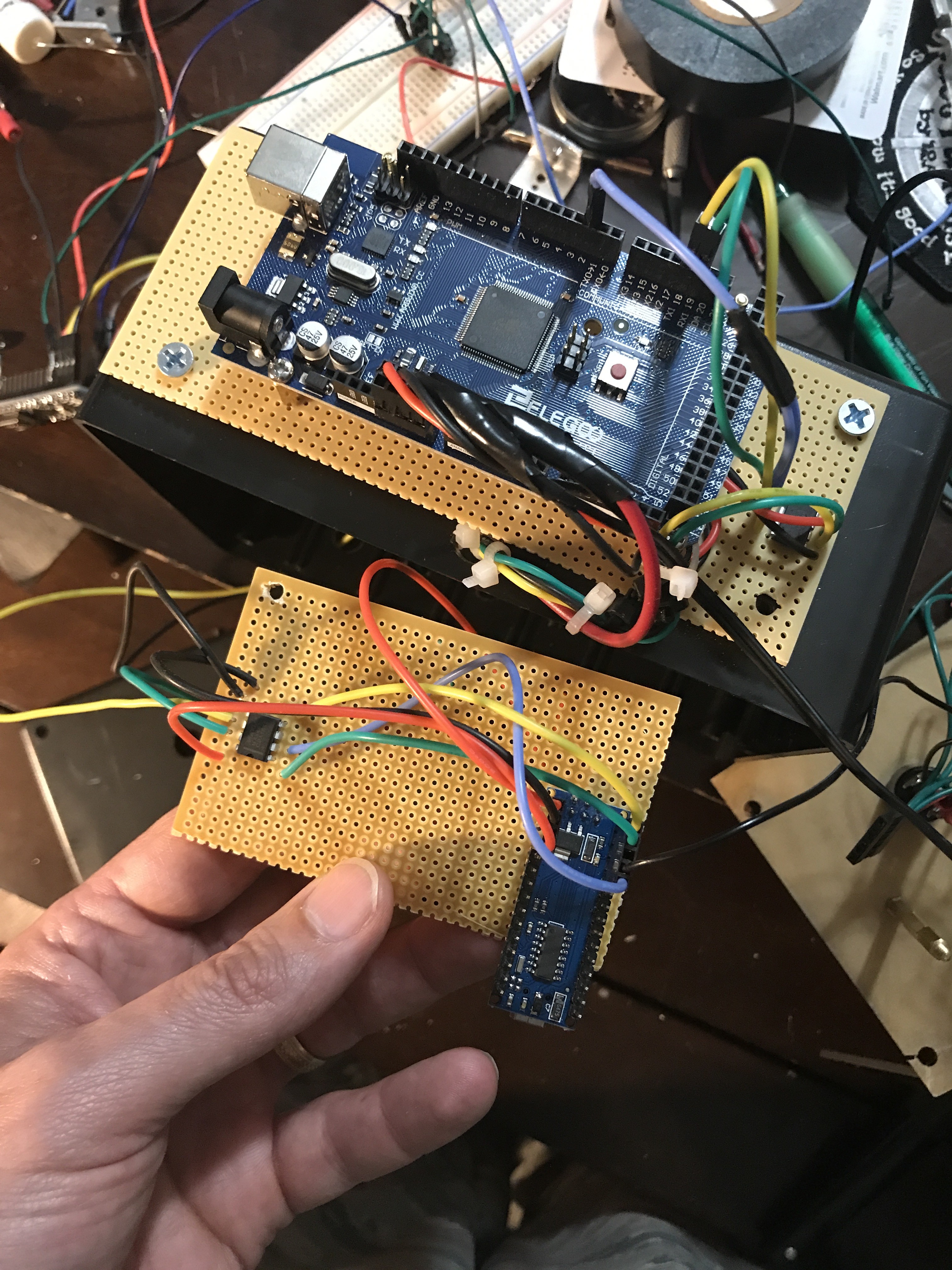
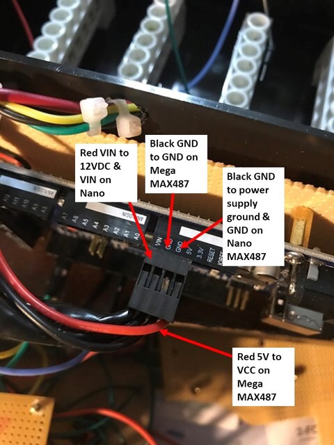
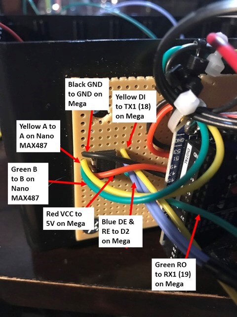
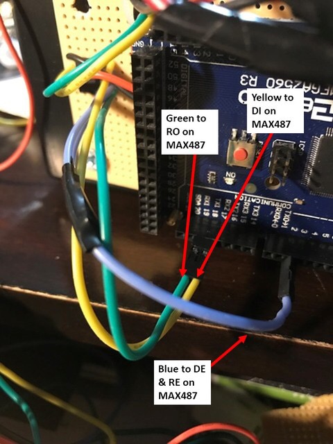
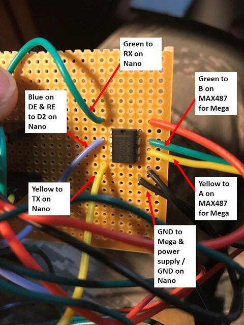
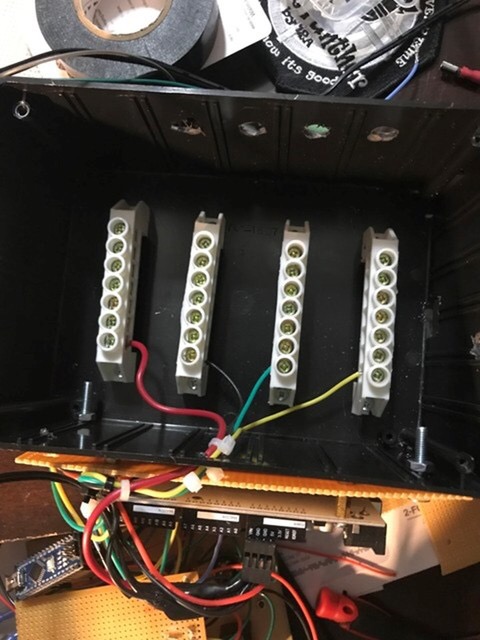
Ok here are some pics of my setup with descriptions.

-
Hans, Thanks for the reply. That was a total frustration post. I think I just need your magic touch! The sketches run flawlessly when run as serial (thanks to you). I’ll get you the code and the wires when I get on the computer where the code is located. Are you using any thing other than the max487 chips? I know it has been mentioned in older posts that additional components may be required. I most likely have a mistake somewhere I assume. I bought some adifruit power distribution blocks to allow me to tie the four lines into a central location. I will eventually create disconnects at the panel so I can easily remove them if required.
-
I’ve reached the point of frustration and now I have to ask for assistance. Here is where I am at: I have hooked up my RS485 bus using Hans method https://forums.eagle.ru/showpost.php?p=3247704&postcount=171 I could not make anything work. I went back to the workbench and hooked up a new nano and new max487 chip and now I get the RX light on the nano and when I start DCS BIOS and DCS World I get the flickering light on the mega and scrolling data on the cmd window. I still can’t get a switch to work. What could I be doing wrong? Sorry if I’m not being clear I’m just pretty frustrated at the moment.
-
I assume this setup would be supported on a RS485 bus to allow for this many nanos?
-
Thanks. I’ll let you know if I can figure it out but I’m literally learning as I go. I’m trying to go from the front to the back of the consoles but this one may happen earlier since I have it on hand. What do you do for the UHF radio? I find some analog ARC-164 ON EBay but I would prefer a digital display. I don’t have a laser engraver so I have to find a source that sells the panel.
-
Hans, Were you able to solve the TACAN problem? I also have an actual TACAN and would be looking to do the same thing. Were you able to use the original pins and plug on the unit or did you re-wire the whole thing? I was planning on tracing the wires back and using the existing pins. Gary
-

DCS-BIOS CMSP Mode Select SwitchMultiPos Issue
Pavespawn replied to Pavespawn's topic in Home Cockpits
Thanks very much! Once again I lean on your knowledge! It compiled but still won’t work. I’ll try to figure out if it may be a bad switch or board. -
Guys, When I copy over the code to upload the CMSP mode rotary I am unable to compile. This is what I am trying to upload: const byte cmspModePins[5] = {8_0, 9_1, 10_2, 11_3, 12_4}; DcsBios::SwitchMultiPos cmspMode("CMSP_MODE", cmspModePins, 5); I have the same problem with any other code where I have to define the position (PIN_0, PIN_1, etc.) Is there something I am not adding? Thanks. I have done some searches but I can't find an answer.
-
Thanks! I feel a bit better knowing I did it correctly. I appreciate the help!
-
I am trying to figure out what I did wrong with my CMSP next button. I cut and paste the command from DCS-BIOS: DcsBios::Switch3Pos cmspUpdn("CMSP_UPDN", PIN_A, PIN_B); My pins are 12 and 11 so I change it it this: DcsBios::Switch3Pos cmspUpdn("CMSP_UPDN", 12_A, 11_B); When I do it will not compile. If I remove the _A and _B then it works but both buttons only count up. Thanks for the noob help guys. I really appreciate it and I hope this clicks for me soon lol.
-
You are my hero! Now I have to figure out comm ports because my fuel panel stopped working when this started!
-
:doh: I used the led library. That is probably my first mistake (besides thinking that I could figure this out). I'll find the OLED library and use that. Yes I was able to get the address of 0x3c. I appreciate the help and hopefully this helps someone who is like me and has never attempted anything like this before.
-
Sorry, I mean your RS485 with the MAX487 chips. I have all that in order but I am not feeling confident if I can’t even get this screen to light up. Lol.