Crumpp
-
Posts
1593 -
Joined
-
Last visited
-
Days Won
3
Content Type
Profiles
Forums
Events
Everything posted by Crumpp
-
I will check it out, I have not experienced the new spotting. The spotting in DCS 1.0 very much reminded me of spotting traffic at work.
-
Not trolling. Spotting airplanes in reality is very tough, it should be in the game. We give up some tactical options with unrealistic spotting settings.
-
What was wrong with the spotting before?
-
I took it for a quick spin. Does not seem like much has changed to me.
-
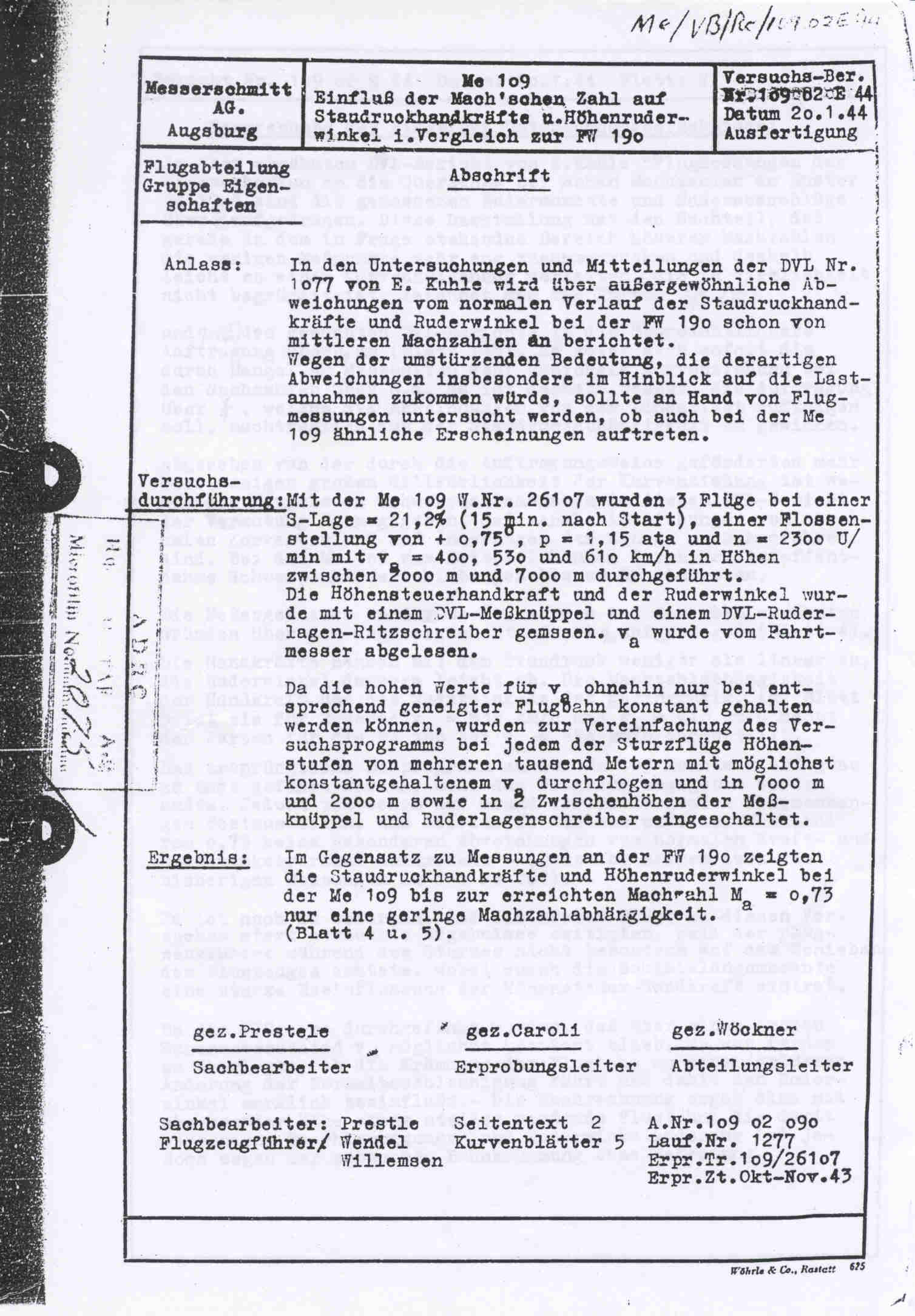
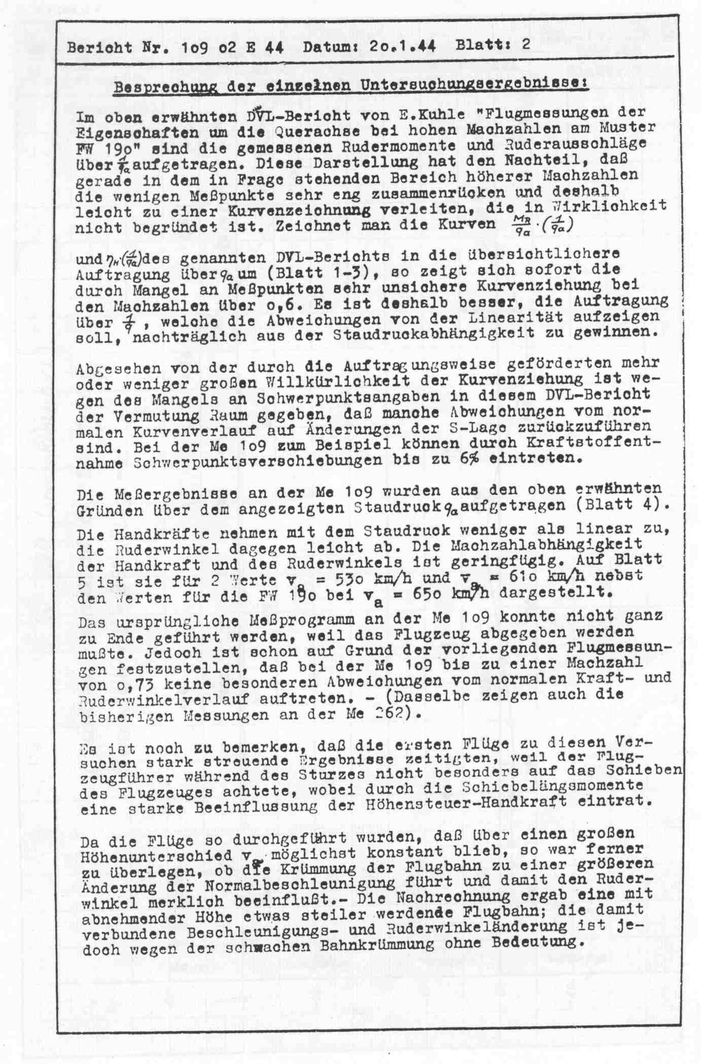
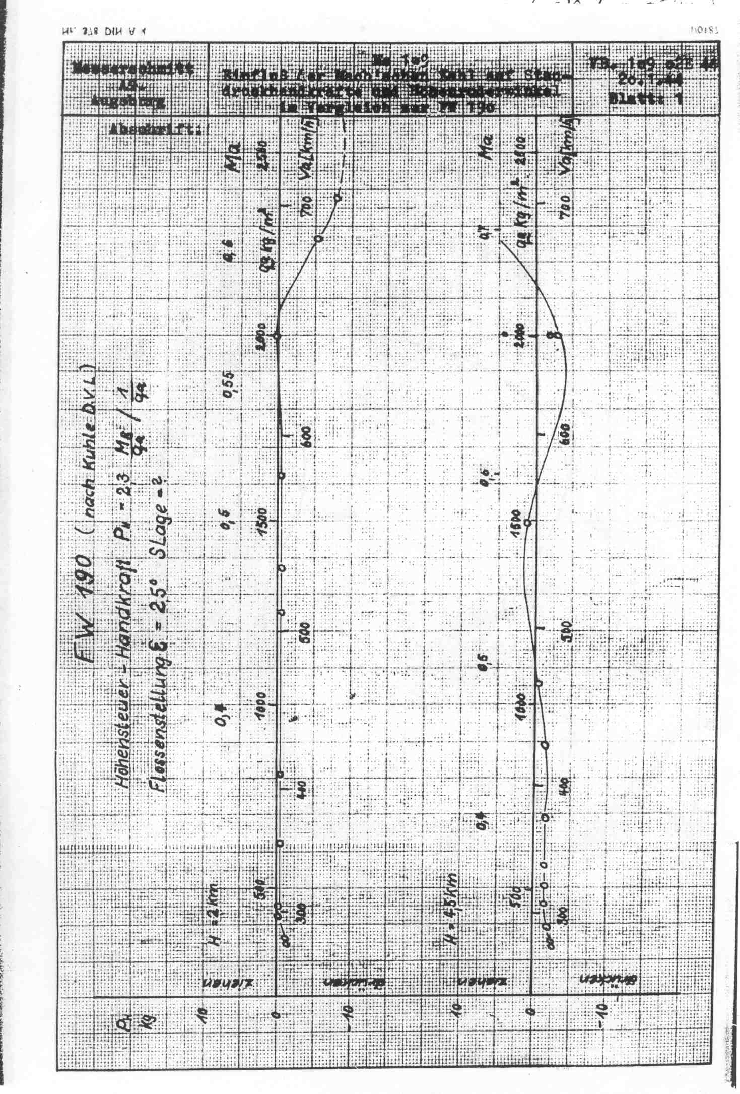
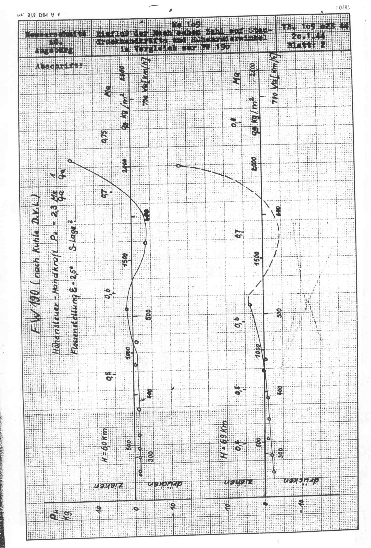
For a World War II fighter, it is very stable and that is evidenced by the curves...assuming their is no change in the Aerodynamic Center and the stability margin it should match the Bf-109G curves. I do not see any design changes that represent a change in the Aerodynamic Center in the Bf-109K series. Maybe this will help people to understand the information presented in the graphs posted on these boards. In the test, the trim is set and fixed at .075 degrees. The fixed trim setting allows the engineers to measure the stick forces over the envelope. If we trimmed the aircraft, the stick forces would always be zero, LOL. Here is the 2Km moved to a trim speed of 450kph. It represents the aircraft in cruise flight. It is not perfect, but folks should have a better understanding of what the stability graphs are telling them.
-
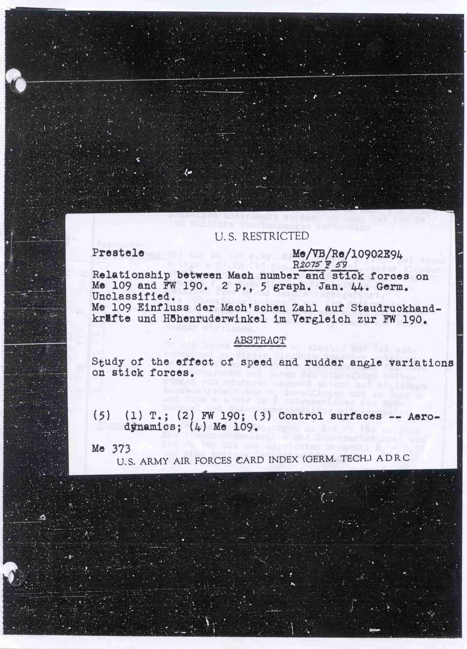
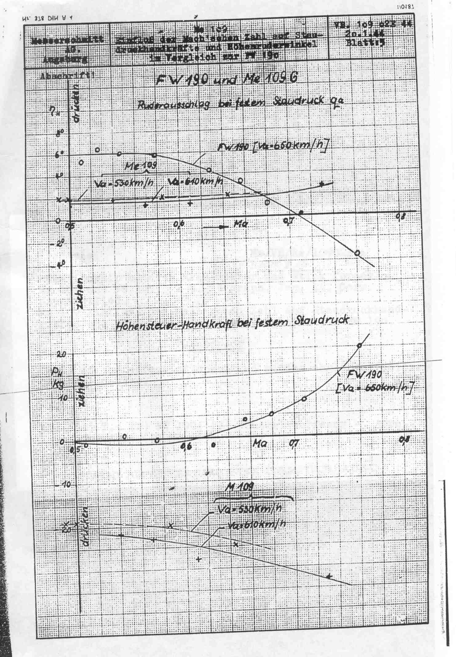
I know...I gave you a copy many months ago. Dear Yo-Yo :) here one could argue what the meaning of Ruder would be, rudder or elevator or aileron. = So it is not black and white.... Höhensteuer is german for control actuator = Hinge in english Höhensteuer-Handkraft = Hinge moment forces = Hinge moment is a common term used in stability and control engineering with very specific meaning Now the graphs are not hinge moments but there is no english term for Hinge moment forces. A moment of force is a measure of the turning effect of a force. A hinge moment force would be the resultant force and exactly describes how Stick Forces are derived from hinge moments. Hence the English Translation....Stick Forces. It is not always easy to translate these documents, Yo-Yo. Even natives make a mistake on occasion.
-
The Spitfire looks beautiful!
-
Left out an important word. Here is the text, pages 7 and 8 are already posted in the thread.

-
I got it...I will post it.
-
I am going to agree with you. In reading the text, there is detailed information on the set up of the elevator both in instrumentation used in measurement, trim settings, and CG location. That is the information you need to perform an investigation of the longitudinal axis stability and control. There is no detailed information on the rudder set up. It could be like the NACA, there were generic instructions for directional control investigations because there just is not much to setting up a rudder for a directional control investigation but I that would be another assumption.
-
It is not static pressure, it is dynamic pressure. It would be isolating mach effects and is probably linked to the earlier dive investigations of both German fighters. If it is rudder, a constant dynamic pressure would prove mach effects on directional stability. If it is elevator, it would prove mach effects on the longitudinal axis. Directional axis has absolutely nothing to do with the longitudinal axis. The only time they are coupled is an inertial roll scenario. That is a jet age phenomenon resulting from long heavy fuselages and very low aspect ratio wings. That is why the only conclusion IF the top graph was rudder angle then the bottom graph was better translated as "stick forces" instead of "elevator forces". Roll inertia was not even discovered until well into the post war. The FW-190 has a short fuselage and high aspect ratio wings....not a good start for an inertial roll scenario. Mach effects were still a big mystery during the war. The debate over whether the control surfaces in mach tuck were frozen or moving at the pilots input was not settled until the last years of the war. You can read the FW-190 dive report. The engineers were baffled by behaviors of the aircraft at high speed especially the pronounced yaw in mach tuck.
-
Falke, I know seitenruder is normally used. Like I said, this has been looked by native speakers on this end. Including one I know, work with, and see almost daily who is also well educated on the practical and theoretical aspects of aircraft. We've literally flown around the world together co-captaining....multiple times, going both east and west. Granted, only he looked at the Graphs and not the text. He was also told the report was an investigation or elevator and rudder angles/control forces so I made have set him up for failure. If it was not for that fact, I would not be pushing back. I actually took it to him because I was searching for the rudder measurements in the report mentioned by the US Government translators and could not find either the text or the graph.
-
First of all, if I am wrong or make a mistake I own it. It is more than one source, Native German speakers, that disagree so please do not cloud the issue. The US Government had professional translators when they processed the report. They too seem to have made the same "mistake". So which is it??? Elevator or Rudder??? I have an equal number of native speakers disagreeing. Unfortunately, not something that is uncommon it German especially with technical language.
-
Pilot G-limit compared to the Bf 109 and Fw 190
Crumpp replied to Dirkan's topic in DCS: P-51D Mustang
Height of the footrest does not do anything. One study concluded it raised relaxed G tolerance ~.3G. All the other studies have concluded it does nothing. Back angle seems to have the most influence on relaxed G-tolerance although some studies have taken into account neck angle. The seat angles were taken from internet drawings. P-51 = 14 degrees or 76 degrees from horizontal FW-190 = 25 degrees or 65 degrees from horizontal Bf-109? = Not sure Spitfire Mk IX = not sure -
Real life pilots know trim is a speed to the aircraft and control force to the pilot.
-
Pilot G-limit compared to the Bf 109 and Fw 190
Crumpp replied to Dirkan's topic in DCS: P-51D Mustang
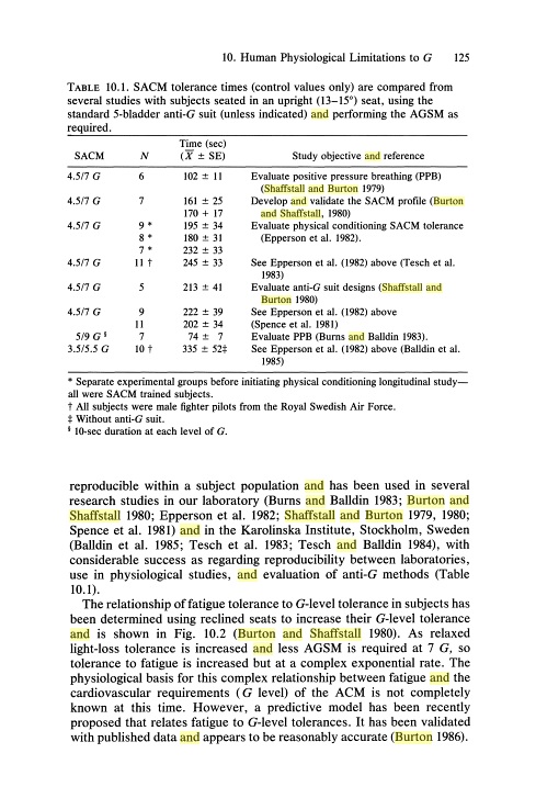
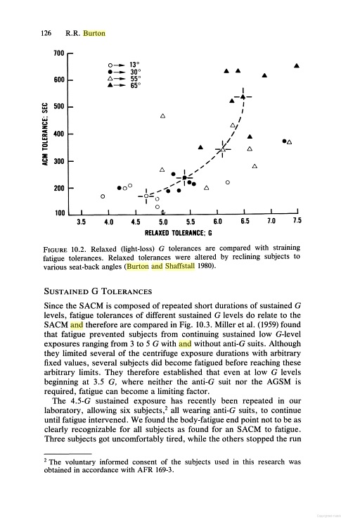
What is G-Endurance? Air Combat Maneuvering is an environment of multiple G levels over an indefinite period of time. It can last from several seconds to a few minutes. G-Endurance is the ability to function in the ACM environment. It is only been recently studied and quantified. The mechanism's that cause G-Endurance limitations are not well known. Some correlation exists in such parameters as lactic acid build up but seems to most strongly correlate with respiration effects. A typical Simulated Air Combat Maneuvering profile is shown below. Now I am sure some readers will note that most World War II Combat does not reach 7G's for 15 seconds of exposure... Don't worry, the investigation concludes the data is applicable to any ACM environment that exceeds 3G. Surprisingly, the lower G ACM environment take longer for the human body to recover. Using a G-suit does not improve your G-Endurance. The longer our pilot is exposed to the ACM environment, the less he can tolerate acceleration to the point of fatigue. Fatigue is noted by increases loss of light at reduced acceleration levels. The more G's our pilot is exposed too without a definite rest period, the less he can handle. How does the pilots seat angle effect this? Quite dramatically.... You can see the mean increase in G-Endurance is 1 minute and 40 seconds comparing 13 degrees with 30 degrees. The difference between the two highest G-Endurance levels is 2 minutes and 40 seconds. That means the same pilot has to quit the fight much earlier simply because his seat is upright. The mathematical model for G-Endurance and fatigue limits is included in the report I posted previously. A good pilot physiology model is just as important to World War II ACM as a good flight model. :thumbup:
-
For being such good engineers, the German language leaves much to be desired sometimes. We searched for months for a "waffengeber" on White 1. The same part with the same function has a completely different name on the Bf-109 series. It is the solenoid switch that controls the weapon synchronization thru the propeller.
-
Unless the Germans discovered inertial roll coupling or suspected it about 5 years before it was known to the rest of the aviation world why would they try to correlate rudder angle to elevator forces?
-
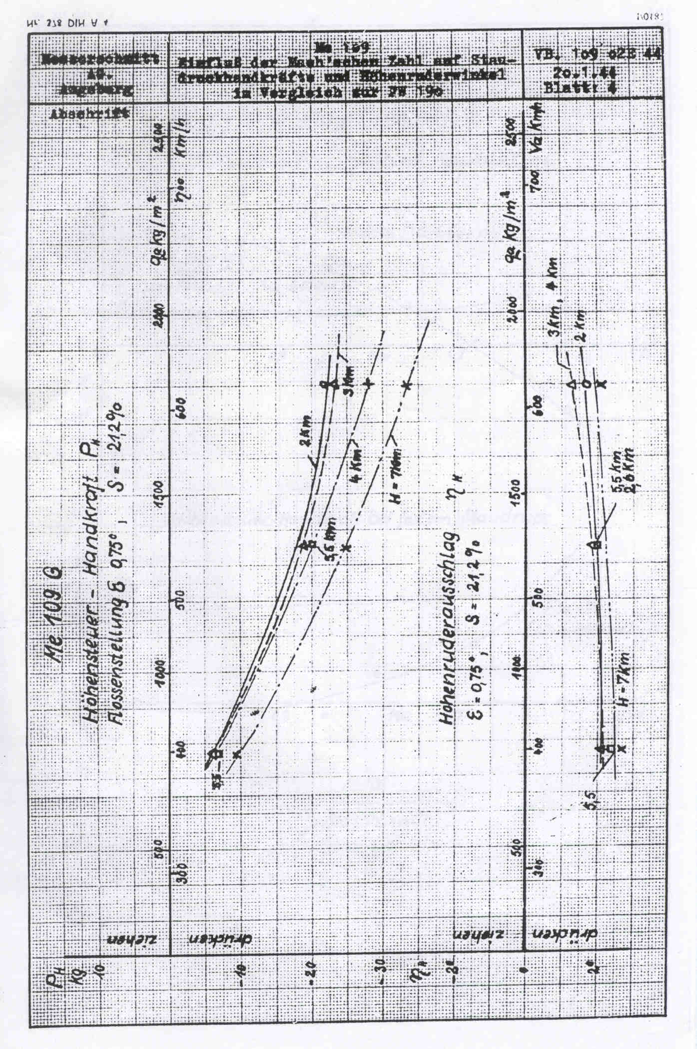
ruderausschlag = Rudder
-
This page is rudder position at the top and it makes sense that the rudder control forces are at the bottom. http://forums.eagle.ru/attachment.php?attachmentid=122039&d=1443711437 The top graph is clearly labeled "Rudder position at a fixed dynamic pressure" I took as simply left and right based on the (+) and (-) standard notations after discussing it with an Austrian pilot/engineer at work. Neither of us could see the point of trying to relate rudder position to elevator forces as they are not coupled in any way. They are not looking for inertial roll coupling events in the FW-190, LOL. Maybe this test is describing an inertial roll event? http://www.wwiiaircraftperformance.org/fw190/fw190-0022-dive.html I took it as aircraft experiences normal mach tuck with a pronounced yaw. This page seems to support that yawing moment developing at high mach numbers. This graphs proves this is a mach effect and not a q-limit. He translated "höhensteuer-handkraft bei festem staudruck" as "Stick Forces at a fixed dynamic pressure". That made sense looking at the other page which definitely relates stick forces to elevator angle. That is the elevator angle to elevator forces measurements of the Bf-109G series. http://forums.eagle.ru/attachment.php?attachmentid=122038&d=1443711437 You can see on the first page the bottom graph is clearly labeled "elevator position"
-
There are rudder curves there. I posted both documents. The rudder and the elevator is shown. I was nice enough to provide the relative stability and control curves for the type. Look at the second page...that is your rudder on the Bf-109G.... All the graphs are labeled with the longitudinal trim information and CG position necessary to make the graphical information meaningful to the engineer. :thumbup:
-
Under the conditions listed at the CG (21.2% MAC) and Horizontal stabilizer trim setting (.075 degrees nose up) listed, the rudder shows ~2 degrees of deflection required and the rudder input force was 5Kg to 37Kg depending on speed/altitude.
-
Here is the rudder stability curves for the Bf-109G series. Any questions on the data and what this means, I will be happy to help.
-
Pilot G-limit compared to the Bf 109 and Fw 190
Crumpp replied to Dirkan's topic in DCS: P-51D Mustang
Why angle the seat and what does it do for a fighter pilot? The posted investigation offers a mathematical model to simulate acceleration effects found in combat on a pilot. The baseline G-Tolerance correlates to a relaxed Rapid Onset Rate (6G/s) threshold to loss of light. Loss of light means the pilot experiences complete lack of vision but is still conscious and not in G-LOC. The method uses the distance between the eyes and the heart. The basic formula for G tolerance: G = Arterial blood pressure * (Specific density of Blood/ distance from the eyes to the aortic valve. For our universal pilot: 98.4mmHG = Arterial blood pressure 13.6 Kg/M^3 = Specific density of Blood (Do not be confused by the units...it is really dimensionless) 385mm = Distance from the eyes to the aortic valve In a 90 degree upright seat: G = 98.4mmHG*(13.6/385mm) = 3.47G In a 14 degree seat: The effect of seat angle is to directly reduce the distance from the eyes to the heart at the inverse cosine of the angle from horizontal or sine of the angle from vertical. 90 degrees - 14 = 76 degrees Sin(76) = .970 385mm * .970 = 373 G = 98.4mmHG*(13.6/373mm) = 3.58G In a 25 degree seat: 90 degrees - 25 = 65 degrees Sin(65) = .90 385mm * .90 = 347mm G = 98.4mmHG*(13.6/347mm) = 3.85G Well that is only .38G threshold increase. That seems pretty insignificant, huh? That is not the whole story of the effect of incline. In fact, the threshold increase is pretty minor. It does make a difference when onset rate is accounted for but even that is not the major effect. There is a real good physiological reason why modern fighter pilots G-protection consists of 4 basic ingredients, a G-suit, Pressurized Breathing System, AGSM, and an inclined seat. http://www.dtic.mil/dtic/tr/fulltext/u2/a178431.pdf In my next post I will go over the details of G-Endurance and how our inclined seats makes such a huge difference as well as the consequences of a pilot exceeding his G-endurance. -
Pilot G-limit compared to the Bf 109 and Fw 190
Crumpp replied to Dirkan's topic in DCS: P-51D Mustang
Can you point that out please? I do not see a thing commenting on the physiology model except to say that in MP the Mustang does not benefit from the USAAF G-suit. As I understand Yo-Yo post, the pilot physiology model is universal.