triise
-
Posts
91 -
Joined
-
Last visited
Content Type
Profiles
Forums
Events
Everything posted by triise
-
UFC starting to take form...
-
Thank you John, this was very helpful. Will try this on one of my steppers now and see how it goes.
-
I see now that it's not the VID69, but the VID60 you need for the altimeter. It has an internal zero setting mechanism, which the VID69 (as I ordered) has not. Which one do you have on order john?
-
triise's A-10C pit Yep, my plan is to use the VIDs for all my instruments. I ordered from the link you provided for me in a previous post. Currently the altimeter is the first project :) (I have a VID 69 for that)
-
John, how do you interface the steppers with DCS BIOS? I see that it currently doesn't have support for steppers, but there will be in the near future. Is there an alternative library I can use?
-
Thanks to Warhogs tips/advice/files I now have a pretty decent cut/engraving for the altimeter. Disregard the big white cut on the diagonal, as I was mixing the mm /inch setup in CamBam late in the evening. Will make another try later [emoji1]
-
Sorry, it's more due to the fact that I read this late yesterday evening. When I look now it's a bit clearer to understand. Thanks for the feedback :thumbup:
-
I'm not sure I understood your question. Are you referring to the fact that my letters don't look the same in the different panels?
-
Quick question: How do I interface my ON-OFF-(ON) switches on the CMSP panel with DCS BIOS? It looks like I should have gotten some OFF-ON-(ON) switches instead, but the ones I've found were expensive and hard to get. Is there some changes that can be made to make this work? I know that it could be done in HELIOS. So it should be possible in DCS BIOS as well to my understanding.
-
Fastened the bolt on the end a bit. It made the turning a bit more heavy, but almost no backlash. Tried to engrave a new panel with very pleasing results compared to the last one.
-
Ok, did some reasearch on my CNC now. Looks like the bearings for the X-axis is of poor quality. I have a lot of bachlash on both X and Y. That would explain the quality issues of my text and engraving. Once again, link doesn't work (at least for me):
-
The forward voltage is 3.4 V, and as far as I can see the ULN2803 also have a voltage drop of 1-1.1 V. That would explain the 13 mA... i think... :joystick:
-
Ok, found out why its working and how I get the current readings that I get. And I learned something new about Darlington arrays, in this case the ULN2803APG. There is a voltage drop of about 1 - 1.2V in the transistor (depending on the saturation current on the collector), the supply voltage is 5V. Then using ledcalc, I should use a 28 ohm resistor, but I do in fact have a 10 ohm 10W at the moment. This should mean that the Darlington indeed works as a resistor, and my mA measurements are correct. My LED's have a forward voltage of 3.2-3.4 V (Ultra bright green). You can read for yourselves: http://pdf1.alldatasheet.com/datasheet-pdf/view/182611/TOSHIBA/ULN2803APG.html Check VCE (sat) on the 4th page.
-
Sure, here is the link: http://www.ebay.com/itm/111340471971?_trksid=p2059210.m2749.l2649&ssPageName=STRK%3AMEBIDX%3AIT Haven't hooked them up yet, but they fit perfectly behind the MFDs. Regards, T
-
Thanks for the input. Look what it looks like with one resistor: ${1} Now I'm using one (1) 10W 10Ohm resistor for all the LEDs. I think I've read that the ULN2803APG does have some internal resistors. Maybe thats why it's working? Also I use 5V supply voltage now, not 12V. for some reason my youtube links doesn't seem to work... link:
-
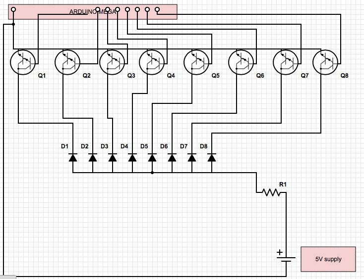
Here is the layout of my curcuit. I've drawn in the transistors separate, but they are in the Darlington array. Also after I switched to 5V supply and added a 1 ohm 10W resistor things seem to work. Also I measured the total Amperes drawn by 1 LED, and it was 13 mA. So things seems to work, but I don't get my calculations to match it. But, if it works, don't fix it :) BTW, I'm using the ULN2803A (6 in total for my caution panel).

-
John, how do you setup your electrical connections? Du you use resistors between the darlington and each led? or do you have one resistor to rule them all ;) I tried with 1 resistor between the 12V power supply and the first four rows of my caution panel (the first darlington). It worked but my resistor got so hot that it melted the wire next to it, in other words: to hot. I used a standard 1/4 W resistor, metal film. Should I put several resistors in paralell? or maybee get a higher wattage resistor? Any tips? Regards, Tore
-
Testing the caution lights panel. Only the first 2 rows operational as I wanted to check if my setup worked. Luckily I by chance tested if I needed a resistor on the 12V supply to all the LEDs, and i certainly did! To bad if I haden't thought about it. Then the whole board would have fried. One 560 Ohm resistor did the trick. The light bleed is not as bad as it looks in the video, but there is some. Here is the video: https://www.youtube.com/watch?v=3trBp1nmDmo
-
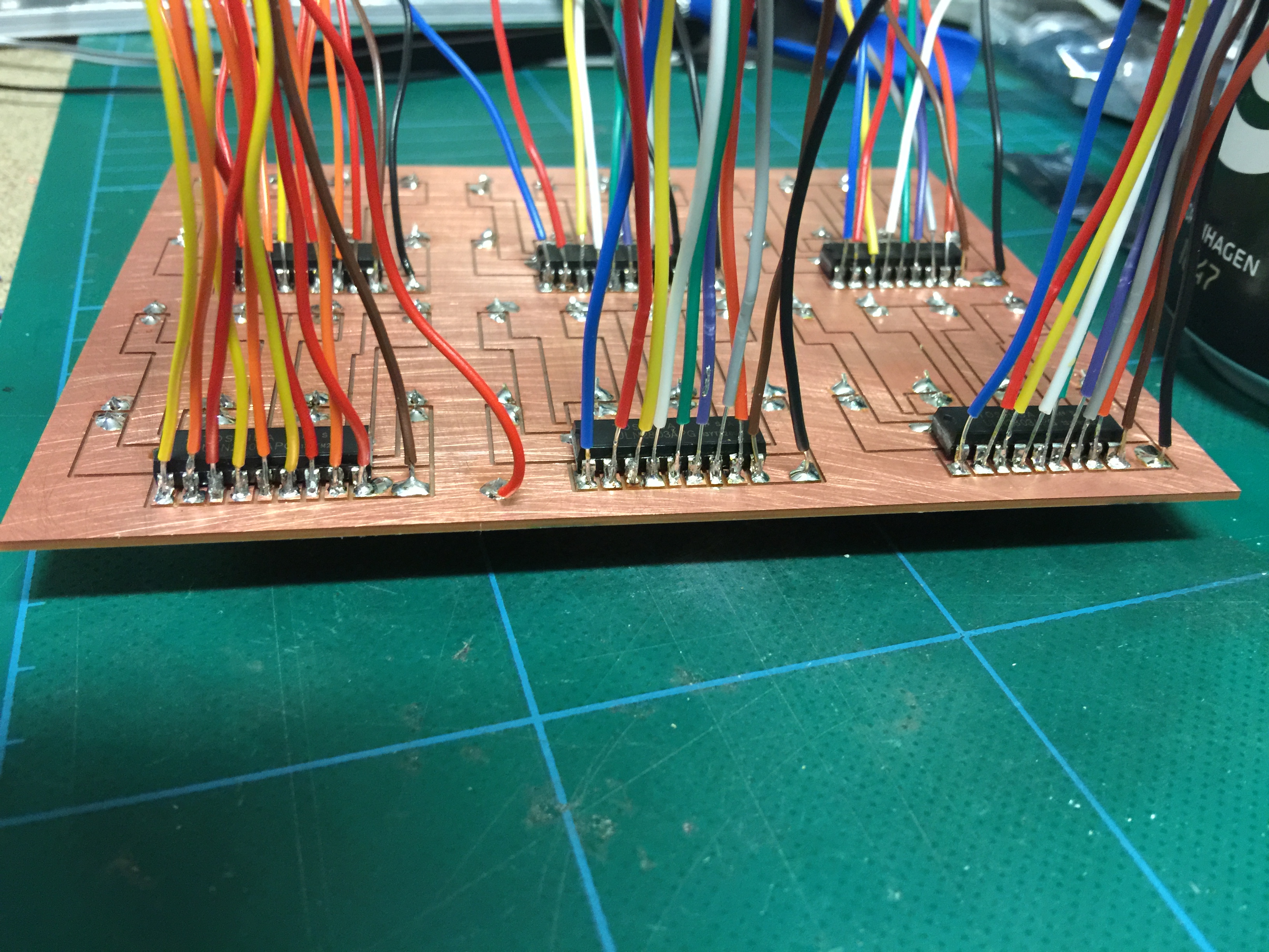
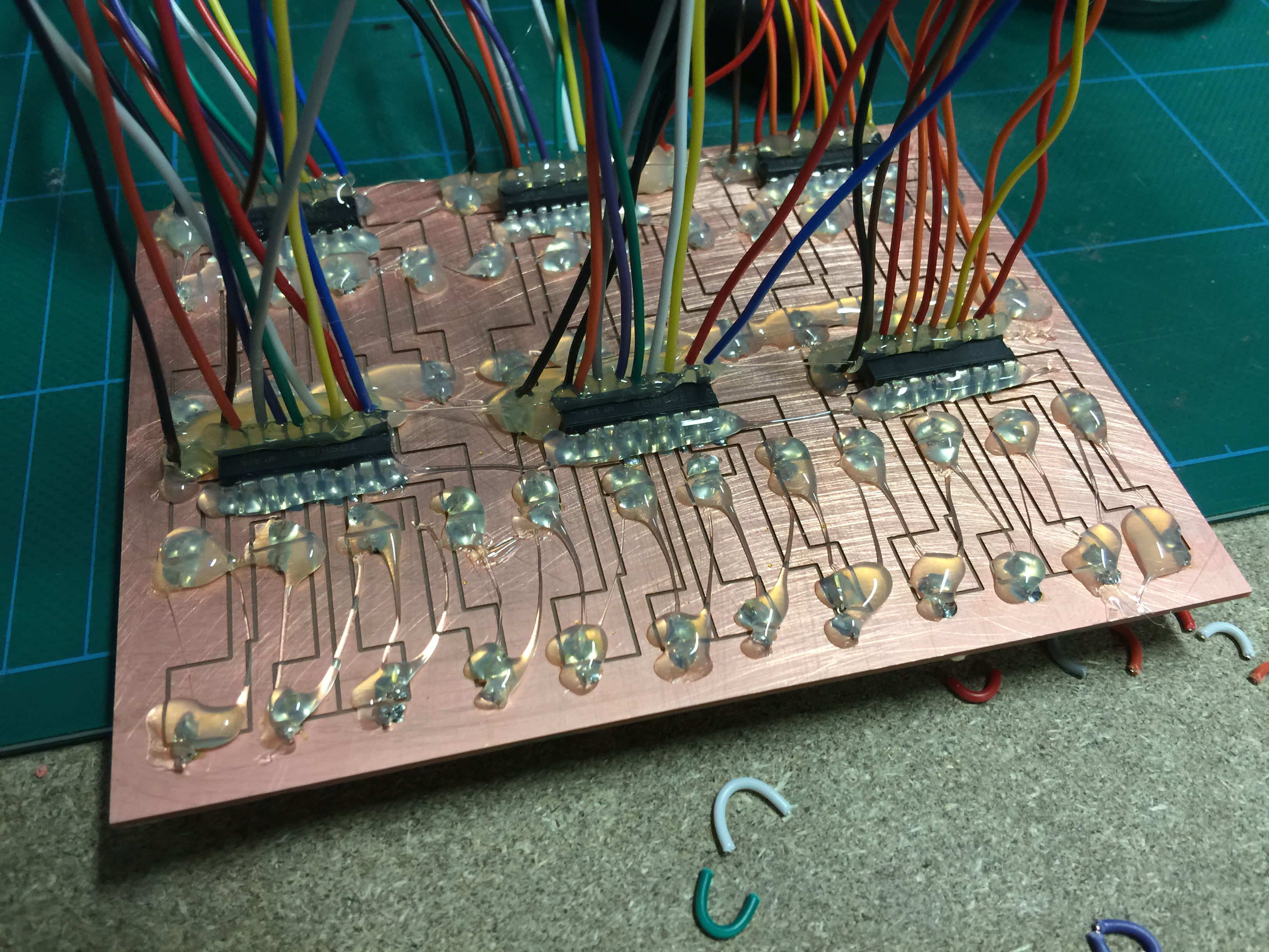
Ok, new update on the caution light panel. All leads soldered Glue gun FTW :) (don't want any short-circuits) Note to self: drill separate holes for the connecting leads, so you don't have to solder them directly to the PCB.
-
Yep, you are certainly correct about that. What I meant was that it did fit within the overall dimensions of the panel. ;) I'm all into compromises, as long as it looks realistic and is functional :pilotfly: Regards, Tore
-
John, thats awesome precision on your mill! May I ask what brand it is? Or did you build it yourself? Now I can understand what you ment by my machine not beeing accurate at all. I'm looking into building my own machine from German parts now. And I'm also trying to find out whats best of "screw-driven" (sorry don't know the english word) and belt-driven axis. With the belt I suppose there is no backlash, but more chance for slack after some time. Do you have any suggestions? The parts will be from cnc-plus.de (same as I buy my end-mills). And I will also buy a Kress spindle (1.5 kW) The only thing about it is that the lowest speed setting is 10K rpm, and that might be a bit high for acrylic cutting i think... Regards, Tore
-
No problem, If you were reffering to the pictures (as you had quoted) it was my PCB. Feel free to use it as you want. Regards, Tore
-
Thanks, then I'll just have to wait for the steppers... :music_whistling: I must admitt that I drew a layout using servos last night and was very tempted to try it out. Whats the main reason that steppers are better than servos for the engine gauges? speed and response? Regards, Tore
-
Were you reffering to mine or Warhogs PCB's? Anyway, here is the .dxf to the PCB i made manually. There is no automatically generated things. 2015-03-26 caution light_panel PCB and acrylic.zip
-
Hi I'm not sure if I understand what you mean. If you think about the PCB's I've been making, they are totally manual work. Polylines and rectangles. I use CamBam for the purpose of this. Attached is the g-code files for the PCB so you can see. I don't have the DXF here right now, but can provide it if you're interested. Caution light panel PCB.zip