ice_pdb
-
Posts
42 -
Joined
-
Last visited
Content Type
Profiles
Forums
Events
Everything posted by ice_pdb
-
Oh!! I took for granted that detail...and also thought that the picture of the device manager showing the com port was from its reset state. So were you able to load the firmware? Remember that it won't show as a joystick in Windows until you configure an axis or button.
-
Device Manager. In your case seems to be 5. Yes, auto start loading. Right click on the mmjoy2 software a make sure you run it as admin. If you don't do it in some Windows it won't allow any hardware modifications. Off to sleep. Later
-
About reset, I meant that the RST pin doesn't have to be permanent shorted. 2 or 3 of inputs should be ok. What I do is once I've identify the serial port of the arduino, check the Auto load and set the correct COM number. Obviously running the soft as Admin, an then reset the arduino. Then the software should detect the serial port being active and it will automatically upload the firmware.
-
So did you try running as Admin and auto start uploading when port present?... Other thing... the reset must not be a permanent input.
-
Does it show the COM port in the Device Administrator ( I use Spanish version of Windows). If it does. Run the MMjoy software as Administrator. Check the correct COM port number. Also you can tick the Auto-start upload when COM port...... Remember that the serial COM port is present for about 8 secs after reset.
-
Ah, I see. Later tonight I'll see this board at home. Thank you Sokol1
-
I'm curious about this pcb.... Does it need to be connected to a shift register? Or directly to data.clock. (...) And also what's the transistor needed? The transistor doesn't have pads. And one diode seems not connected
-
You're totally correct. I surely didn't interpret correctly the truth table. For instance https://www.alps.com/prod/info/E/PDF/MultiControl/Switch/RKJXL/RKJXL.pdf can be used since it has separate center push button but lacks encoder. Just one question, the pcb needed for making the 4 way + encoder work, needs to be connected to a shift register?
-
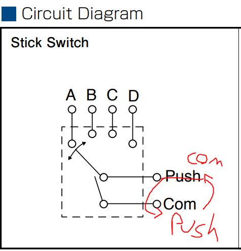
@Sokol1_br Wow, that's really weird... it's not what the diagrams show about the device.... @trigen I'd like to have one of those to test myself :lol: I would check like this without diodes. 1) Without activating any switch test continuity between COM and PUSH COM - A;B;C;D PUSH - A;B;C;D 2) While activating Switch A;B;C and then D test continuity with COM and PUSH. One should have Continuity with the 4 way switches but not the other... I guess that if this is true the one that doesn't have continuity is the real PUSH and the other is the COM. This way you may be able to check if the Push and COM are swapped, analyzing the Circuit Diagram they seem so. :D :doh:

-
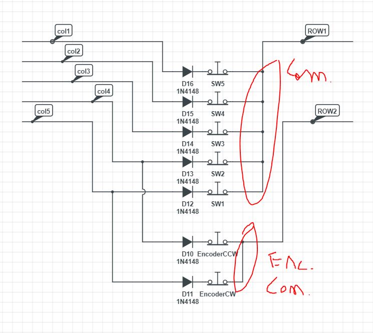
To summarize. Encoder works ok But 4 way switch activate your push button? Try the diagram I've posted before. 2 ROW 5 Col
-
I've watched the schematics of the device, it should work with the diodes. Did you check if the diodes aren't conducting both way? Show in a schematic how you did connected it?.
-
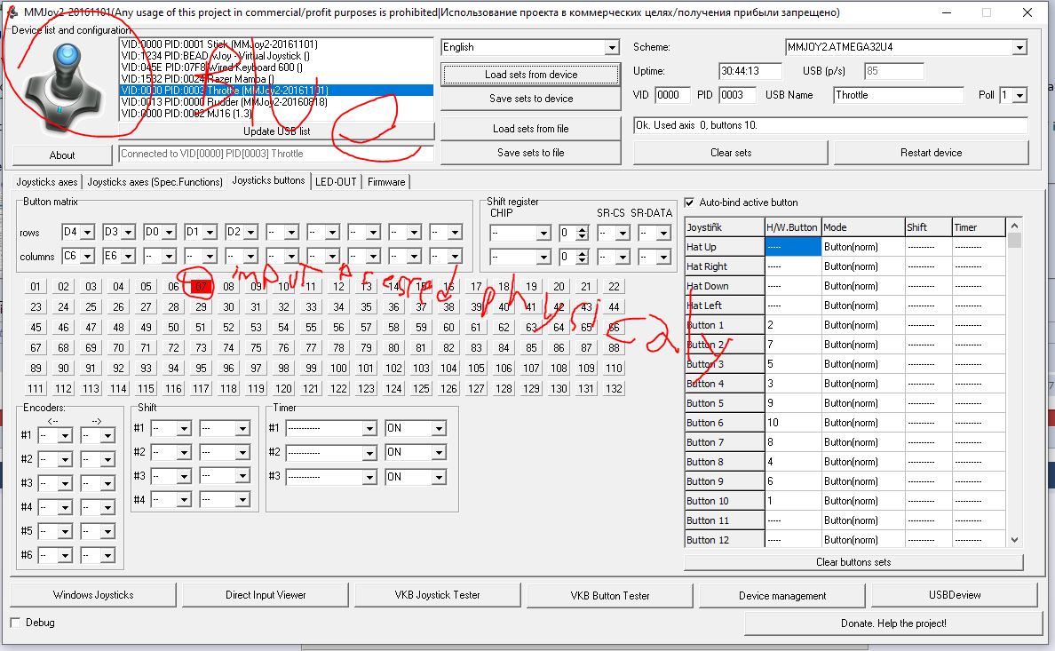
Why do you use old version firmware?... why do you use Switch On function with timer in button 35? Also if you don't click in the device you want to pol and load settings from device you don't see the inputs...
-
I would do it like this...
-
I've made a dumb question... lol. You're right looking with more attention the diodes are in same polarization...
-
@Sokok1_br Since I never used encorders myself, I didn't check about diodes. But the only diff with regular switches are the polarization of the diodes. Also I had in mind the mjoy16 connection that it's the same as switches. Is there any reason for connecting diodes reversed in encoders?
-
hi @trigen It's 5 switchs and an encoder.... just see it as what it is. Basically you wire 7 push buttons and then configure the 2 of them that are connected to the encoder. What's your doubt if I may ask?
-
@Fihnakis I don't use encoders... so, I can't provide any help with them. Did you try configuring only encoders... with other matrix? that way you can test them.
-
mega_mozg_13 Exactly, I do plan to use gears to use the 360 degrees of the TLE resolution. Thank you for your time! :)
-
@mega_mozg_13 hello!! Thank you for your firmware!! I'm using TLE5011, and MMJOY2 register about 30000 points, is it possible to use those directly and not through bit resolution selection ? Since it's limited to 14bits using almost the half of the points that TLE inputs. Sorry if I can't make myself clear, my language is Spanish so my English may sound funny
-
I also remember having a similar problem with windows joystick properties/test... I had to look for the not working joystick Windows Registry and manually deleting that key....
-
I think you need to configure your MMJOY2 with Poll with a "-" https://gyazo.com/02ab3cc51dbc437129b5660c77632342
-
Mmjoy2 170606?
-
Can the Gazelle use it's laser to designate for others?
ice_pdb replied to ice_pdb's topic in SA-342M Gazelle
Thank you @Ramsay -
Hello all. Is there any way to lase a target for a GBU?
-
Hi all, is this behavior correct? I would say that it should have drop like a rock, since TORQUE indicator shows that' there's no lift... https://www.youtube.com/watch?v=cBfl6zmzhvk