The_Fragger
-
Posts
843 -
Joined
-
Last visited
-
Days Won
4


-
Dear Community, There will be a German-speaking Q&A on the MILTECH-5 Discord server on April 27th at 8 p.m. The entire DCS community is welcome to ask us any questions you want. Even though this conversation will be mainly in German, we will endeavor to answer questions from the English-speaking community as well. Sincerely, MILTECH-5 https://discord.com/invite/jq4WV42d99
-
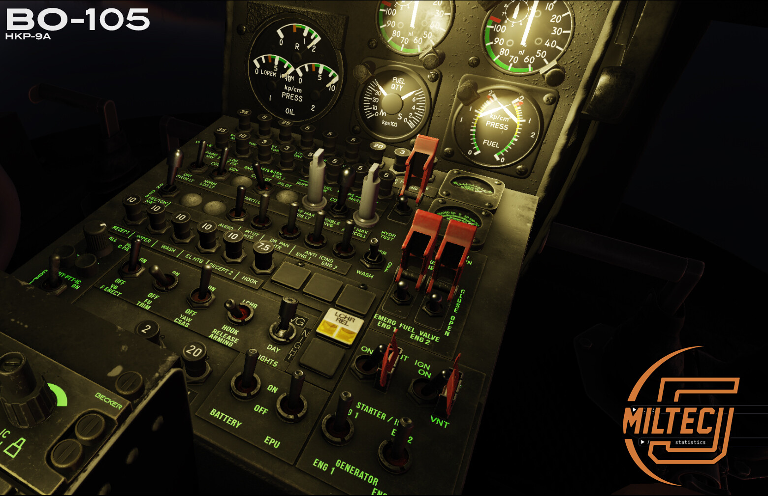
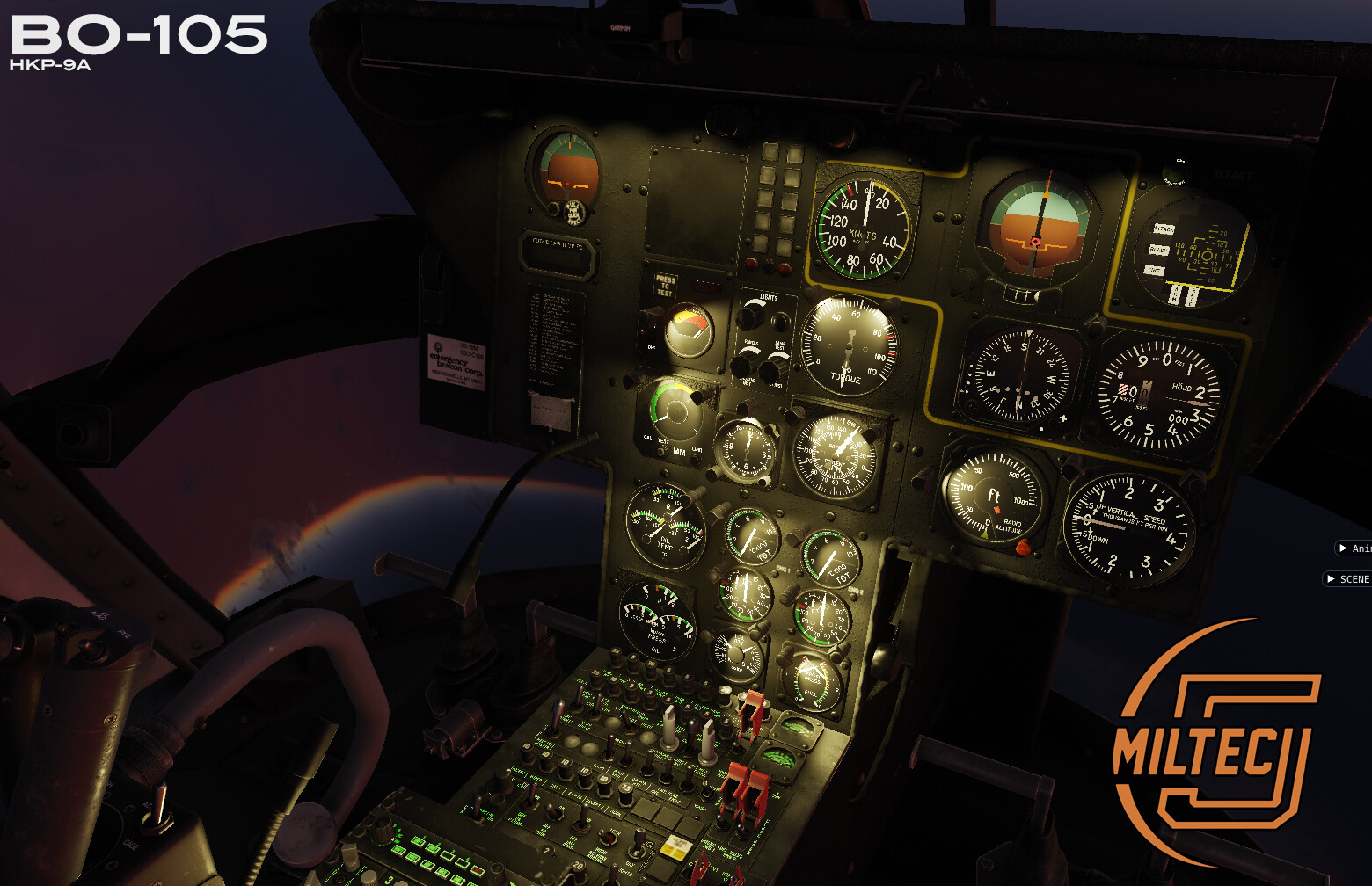
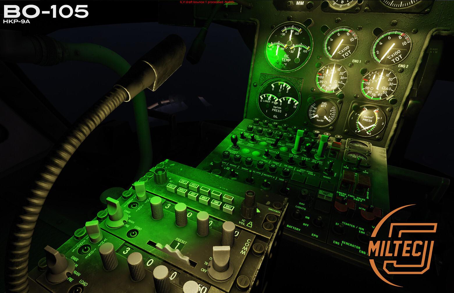
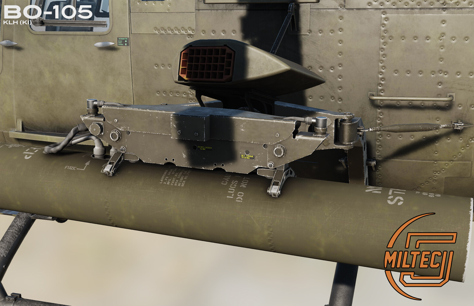
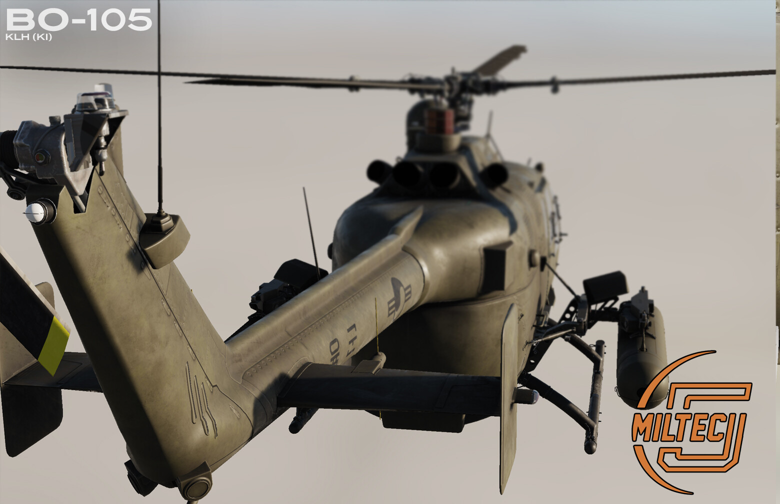
DCS-BO-105 Progress news for April 2024 FM OVERVIEW We are currently in the process of connecting all other instruments to the corresponding bus routes. All instruments will be connected correctly according to the circuit diagram and will react accordingly. This includes power supply, light intensity, magnetic switch behavior and instrument failure. We have also almost finished integrating the drag and wind forces from all external components of the helicopter. The downwash MEDUSA-FM is 50% done as well. Further progress on the flight model is blocked until the altimeter, speed indicator and and compass are done code-wise. FORCES, WIND and DAMAGE Since the MEDUSA system monitors the entire helicopter, all forces such as penetrating wind, stabilizers, OAT (Outside air temperature), damage and blown parts are taken into account. For example, if a rotor blade is broken or missing, the MEDUSA rotor task will take this into account and recalculate the flight behavior. MEDUSA ROTOR SYSTEM The rotor system was implemented accurately. This also includes the rigid rotor head directed 3° forward and ~1.5° forward to the right. Currently we are in the process of aligning the line of sight indicator compass to the magnetic compass. Since the magnetic compass shows the real position of the helicopter, the line of sight compass may differ in certain circumstances. A "+" (plus) or a circle indicator will tell you if you need to adjust the line of sight compass. You will be able to calibrate the disc (indexed rotation of the compass disc) and adjust it to the magnetic compass with a switch. ELECTRIC BUS The electric bus is finished and is just waiting to receive signals from the remaining devices. It's 100% implemented according to the circuit diagram. WEAPON SYSTEM The weapon system is currently in our backlog and will be implemented when the majority of other systems are complete. This is one of the last tasks for MEDUSA. As always, this will be implemented exactly according to the circuit diagram. This includes, but is not limited to: SELF TEST Wire cut cases Power problems The weapon system communicates with the line of sight indicator, YAW control and the current position of the helicopter. YAW CONTROL INSIGHTS When YAW CONT is on and the "SIGHT LINE" ON switch on the collective is pressed/held, the helicopter will always follow the left/right angle of the sight unit (105° left/right). However, the pilot always has control over the helicopter and must ensure that he is always within the line of sight limit (line of sight Indicator Limits -> 3° left/right). If the conditions are not met, the HOT can't be fired. If the HOT is in flight and the pilot deviates from the 3°, the HOT's communication wires are cut. If steering inputs are too hard, the hydraulic system switches from System 1 to System 2 (Displayed on the warning panel). This automatically switches the YAW CONT magnetic switch to OFF. In this mode the helicopter is no longer able to follow the periscope. This entire process is monitored by the MEDUSA HYDRAULIC task and the MEDUSA POWER SUPPLY task.
- 709 replies
-
- 15
-

-
Hi. anyone also have OMNI/SPOTLIGHTS doesn't cast any glare anymore in the Model Viewer ?
-
This is too early to say. We plan(!) an AI feature for mouth synch on F5 menu...maybe more straight forward. but like I've said - it's too early to say. There're a lot of things to investigate in order to say: "Yes - that's possible".
-
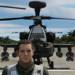
While coding finishing in the background, we are testing additional features to make the overall look more reralistic. This also includes natural behaviours of the character/Pilot/Co-Pilot (facial animations) We are working hard to implement these features to the DCS-BO-105. The first look looks promissing in our opinion. What do you think ? Keep in mind that the endresult is up to the engine. Meaning that the current Animation Test is WIP. CharacterCreator_5i3Iv1vBuz.mp4 CharacterCreator_bNuFSyqZq6.mp4
- 1338 replies
-
- 13
-
-

-
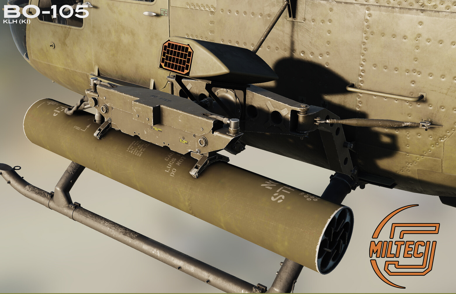
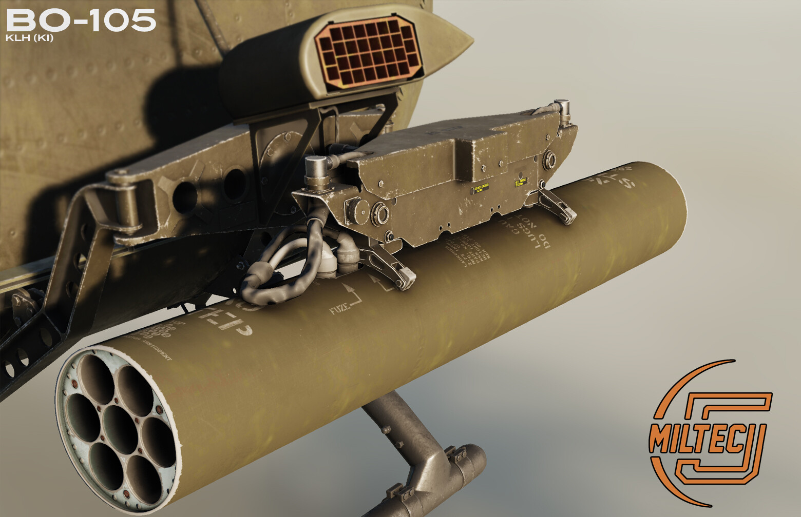
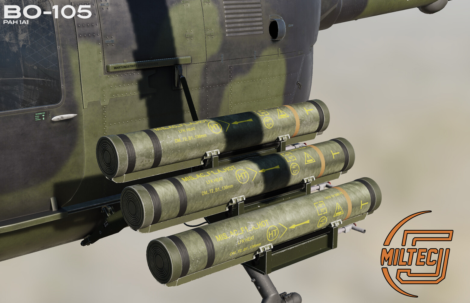
Dear Simmers. There is always a way to convince the enemy that he is evil. One of them is to convince the enemy with HOTs and one way is to curse at the enemy. Another way, if everything fails, is to convince him with lead. That's why we have a G36 - this is planed. I know that the Magazine is transparent....but the renderer thinks it's not We also plan to share some inflight Video in the next months.
- 1338 replies
-
- 18
-
-
-
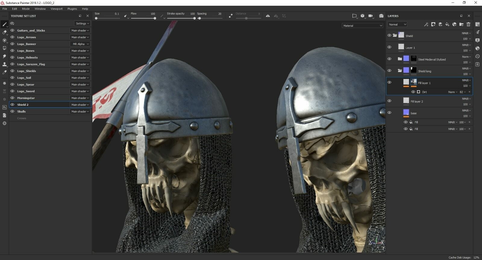
The Name of the Bounding Box should be : TYPE = "bounding_box"; Bounding box must (!) cover the whole 3D objects. I suggest to make it bigger (just in case) For your cube: - Apply a Standard (Legacy) Material (only these work) - apply material to object - Make Cool - Export
-
ich denke es ist besser wenn wir uns mal treffen. Vorzugsweise Discord (MILTECH-5). Dort können wir uns mit meinem Coder treffen, der Euch Fragen beantworten kann. Wie schaut es morgen (Samstag 03.02.2024) aus ? Hättet Ihr da Zeit ?
-
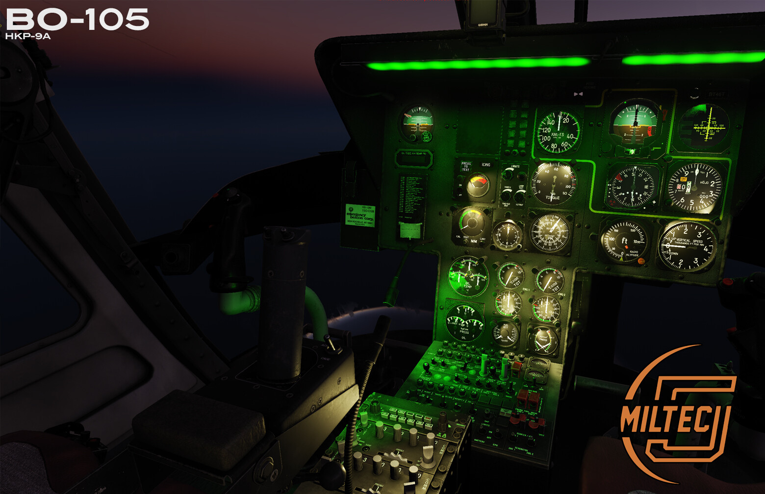
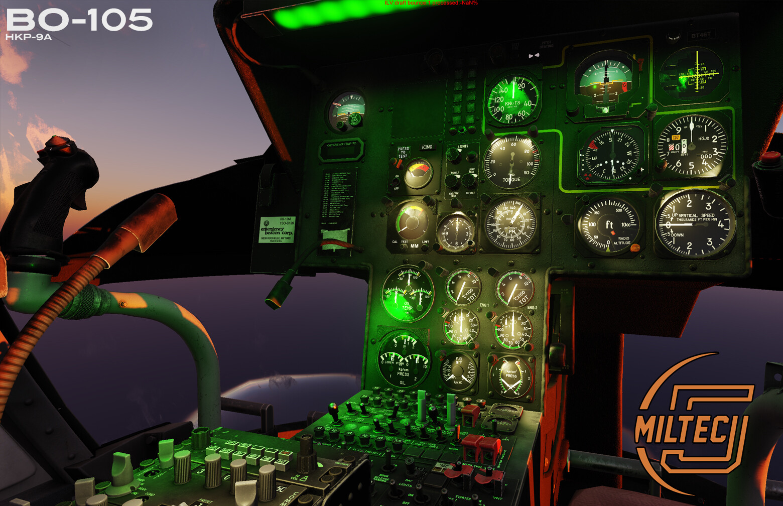
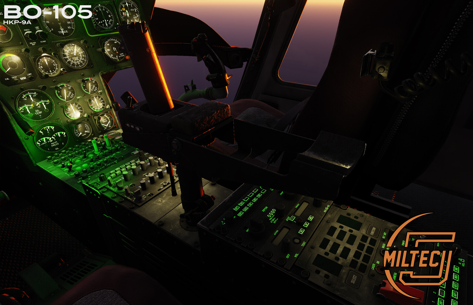
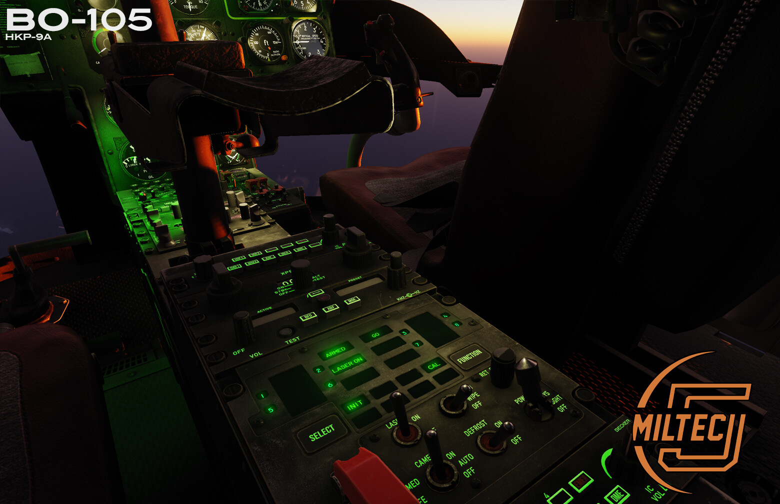
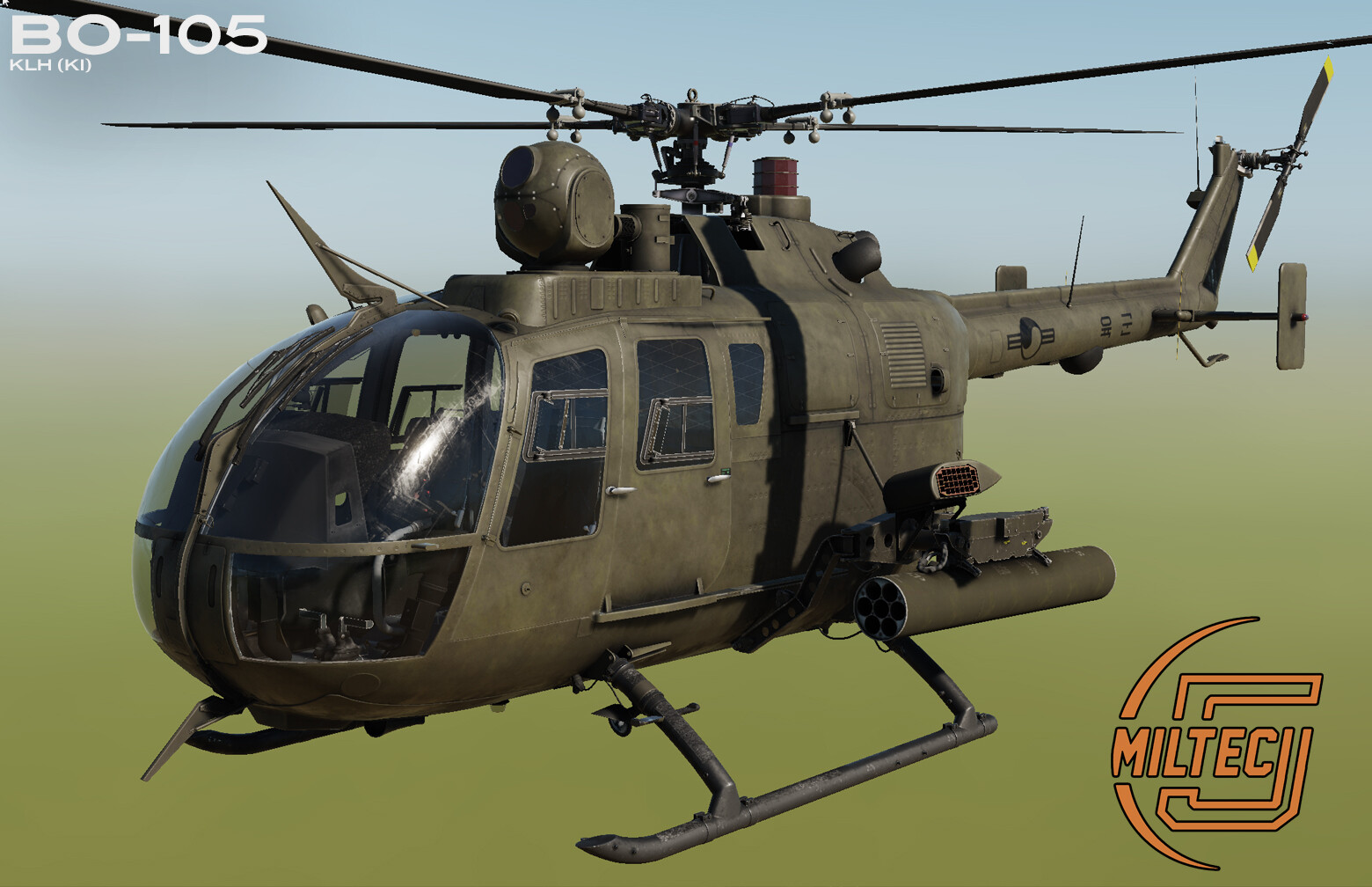
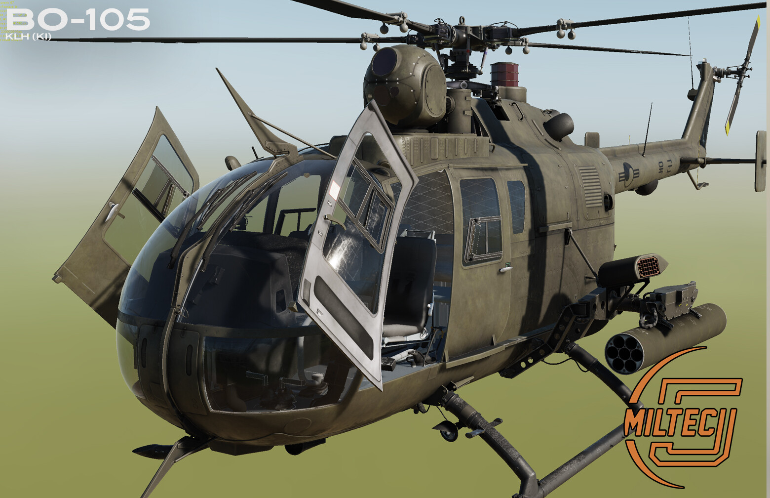
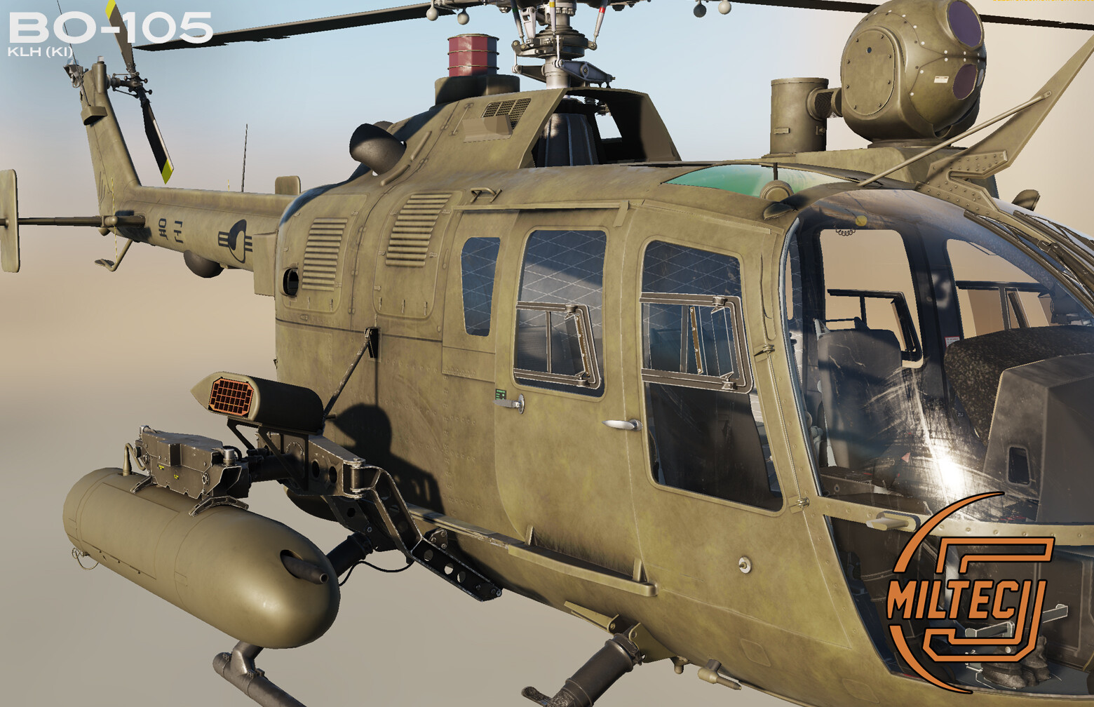
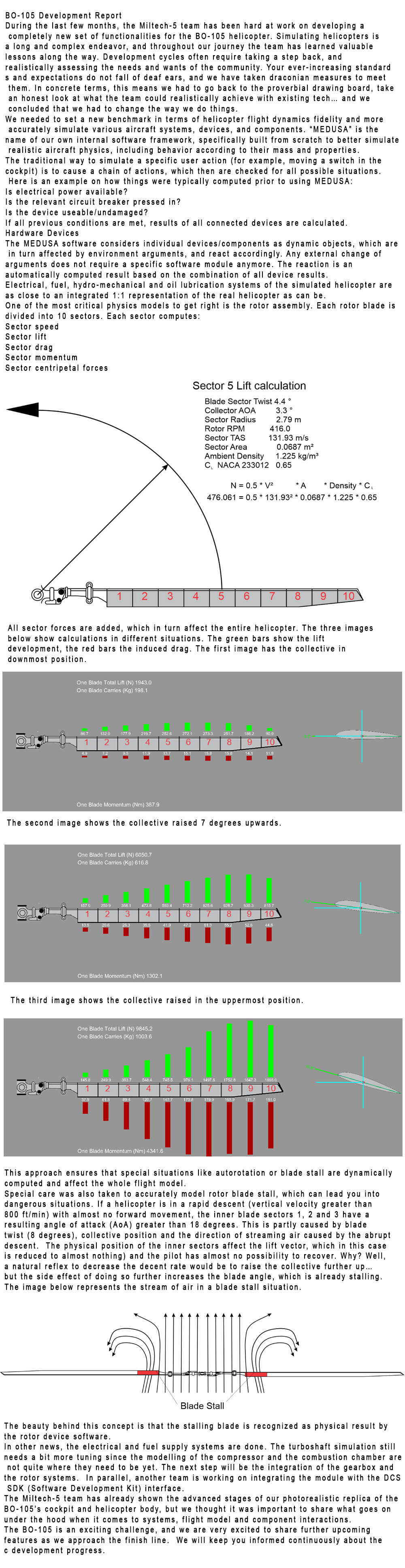
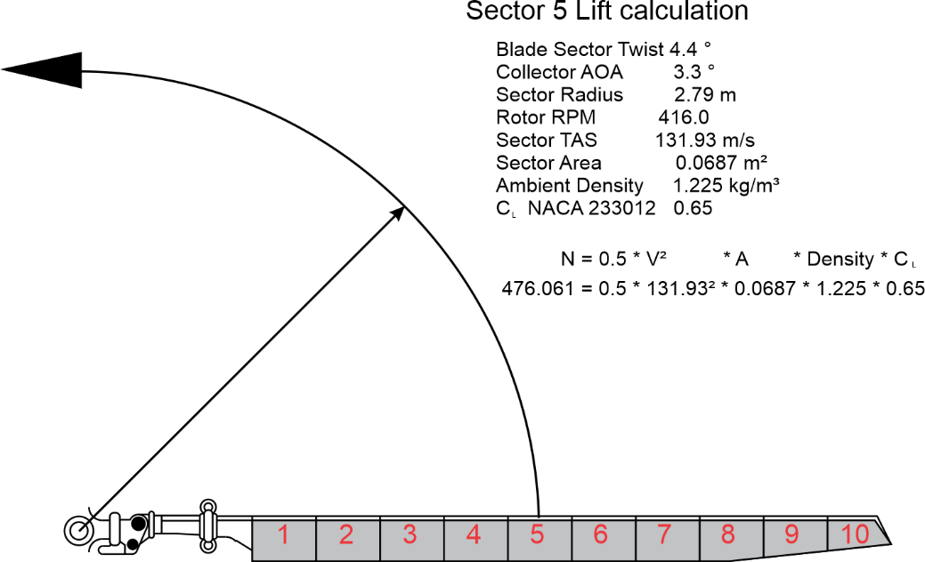
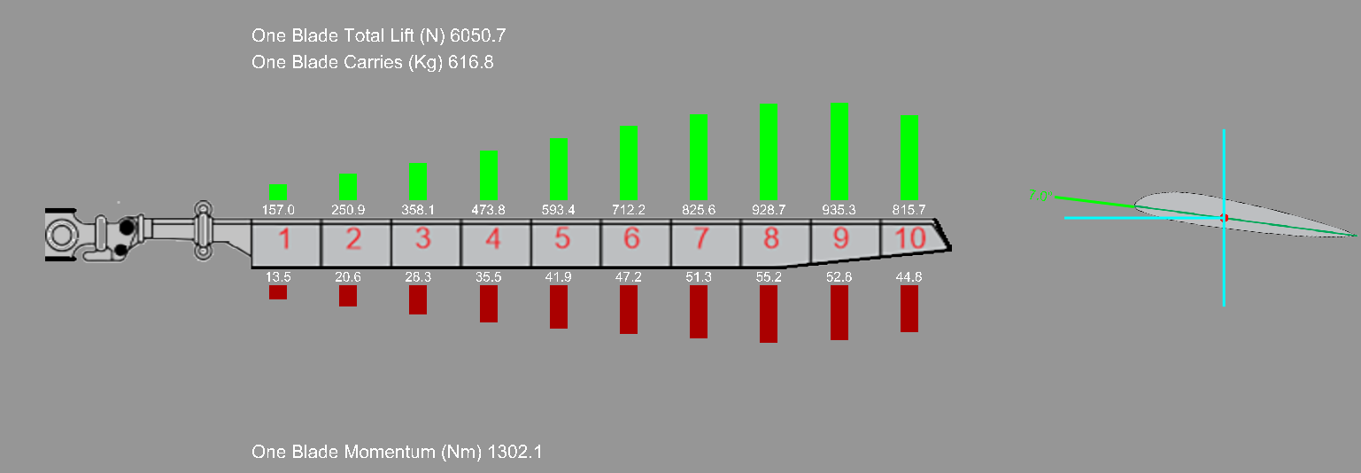
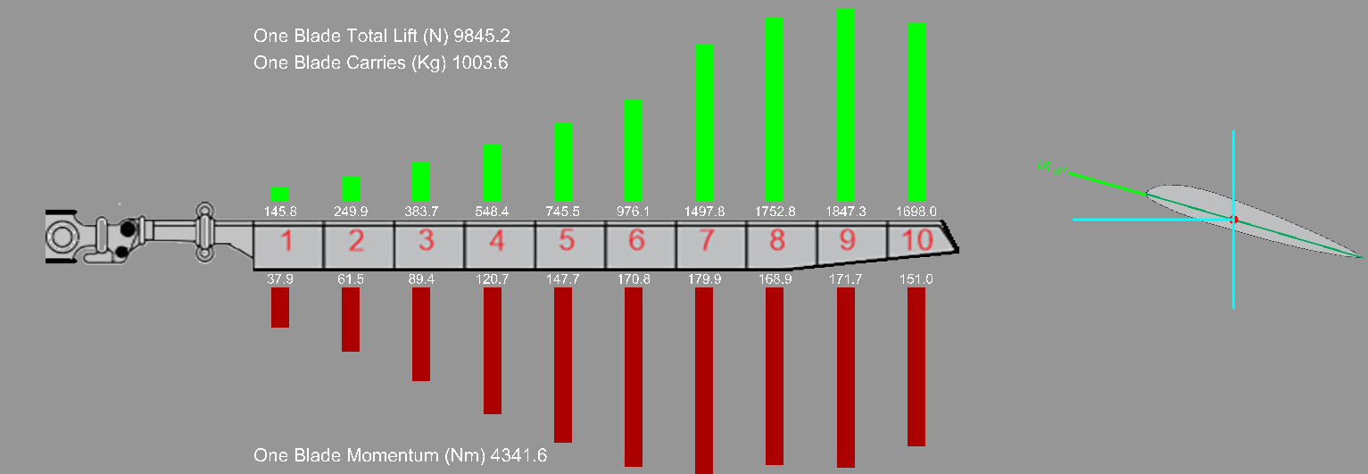
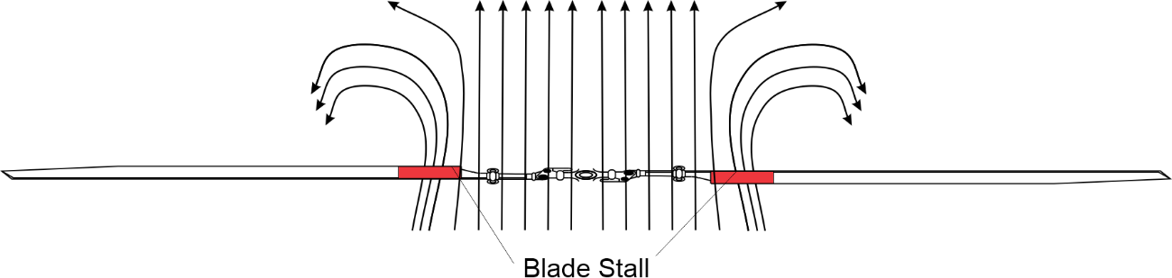
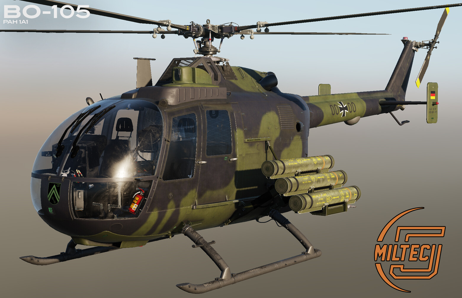
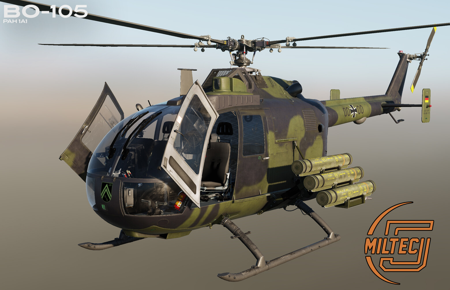
BO-105 Development Report During the last few months, the Miltech-5 team has been hard at work on developing a completely new set of functionalities for the BO-105 helicopter. Simulating helicopters is a long and complex endeavor, and throughout our journey the team has learned valuable lessons along the way. Development cycles often require taking a step back, and realistically assessing the needs and wants of the community. Your ever-increasing standards and expectations do not fall of deaf ears, and we have taken draconian measures to meet them. In concrete terms, this means we had to go back to the proverbial drawing board, take an honest look at what the team could realistically achieve with existing tech… and we concluded that we had to change the way we do things. We needed to set a new benchmark in terms of helicopter flight dynamics fidelity and more accurately simulate various aircraft systems, devices, and components. “MEDUSA” is the name of our own internal software framework, specifically built from scratch to better simulate realistic aircraft physics, including behavior according to their mass and properties. The traditional way to simulate a specific user action (for example, moving a switch in the cockpit) is to cause a chain of actions, which then are checked for all possible situations. Here is an example on how things were typically computed prior to using MEDUSA: Is electrical power available? Is the relevant circuit breaker pressed in? Is the device useable/undamaged? If all previous conditions are met, results of all connected devices are calculated. Hardware Devices The MEDUSA software considers individual devices/components as dynamic objects, which are in turn affected by environment arguments, and react accordingly. Any external change of arguments does not require a specific software module anymore. The reaction is an automatically computed result based on the combination of all device results. Electrical, fuel, hydro-mechanical and oil lubrication systems of the simulated helicopter are as close to an integrated 1:1 representation of the real helicopter as can be. One of the most critical physics models to get right is the rotor assembly. Each rotor blade is divided into 10 sectors. Each sector computes: Sector speed Sector lift Sector drag Sector momentum Sector centripetal forces All sector forces are added, which in turn affect the entire helicopter. The three images below show calculations in different situations. The green bars show the lift development, the red bars the induced drag. The first image has the collective in downmost position. The second image shows the collective raised 7 degrees upwards. The third image shows the collective raised in the uppermost position. This approach ensures that special situations like autorotation or blade stall are dynamically computed and affect the whole flight model. Special care was also taken to accurately model rotor blade stall, which can lead you into dangerous situations. If a helicopter is in a rapid descent (vertical velocity greater than 800 ft/min) with almost no forward movement, the inner blade sectors 1, 2 and 3 have a resulting angle of attack (AoA) greater than 18 degrees. This is partly caused by blade twist (8 degrees), collective position and the direction of streaming air caused by the abrupt descent. The physical position of the inner sectors affect the lift vector, which in this case is reduced to almost nothing) and the pilot has almost no possibility to recover. Why? Well, a natural reflex to decrease the decent rate would be to raise the collective further up… but the side effect of doing so further increases the blade angle, which is already stalling. The image below represents the stream of air in a blade stall situation. The beauty behind this concept is that the stalling blade is recognized as physical result by the rotor device software. In other news, the electrical and fuel supply systems are done. The turboshaft simulation still needs a bit more tuning since the modelling of the compressor and the combustion chamber are not quite where they need to be yet. The next step will be the integration of the gearbox and the rotor systems. In parallel, another team is working on integrating the module with the DCS SDK (Software Development Kit) interface. The Miltech-5 team has already shown the advanced stages of our photorealistic replica of the BO-105’s cockpit and helicopter body, but we thought it was important to share what goes on under the hood when it comes to systems, flight model and component interactions. The BO-105 is an exciting challenge, and we are very excited to share further upcoming features as we approach the finish line. We will keep you informed continuously about the development progress.

- 7 replies
-
- 23
-
-
-
Dear Simmers. Sorry, we currently cannot provide you with updates. Stay tuned.
- 1338 replies
-
- 11
-
-
-
- 1338 replies
-
- 12
-
-

DCS: Roadmap (unofficial - NO DISCUSSION HERE)
The_Fragger replied to Silver_Dragon's topic in DCS 2.9
Ah sooo nullnull
.jpg.b80c74c589b75ea41584076f10a2f9f0.jpg)