
Roger01
-
Posts
236 -
Joined
-
Last visited
Content Type
Profiles
Forums
Events
Posts posted by Roger01
-
-
Stepper motor get a "reset" position (or sync) when DCS bios start?
-
I'm not very smart ;) but I read a lot this (and other) forum, to see the maximum of cockpits and constructions to know what I must to do.
I'm seeking (a long time after) for stepper motors too (gauge) but I see is realy hard to make a 360° without return back like this (this is a 180° servo) :
-
Hi,
What MEGA do you use for Master RS485?
There's :
With pin BUT only 6/9v VIN
And this MEGA :
6/12v VIN but without pin
I think the best is to use 12v for all Arduino board in VIN.
5V won't run (6v mini) if I use an old PC powerDC.
Thanks a lot, and nice to see your cockpit!
-
Thanks for pictures. For the LCD, it's not a problem vite my 3D Print. I can make a support plate.
For the UFC and CDU I was making a pcb to do a matrix output, but I need to buy UFC and CDU to get the dimensions (milimeters) to do that.
And I have a glue gun if needed to maintain the pcb.
I note for the annunciator.
[Edit] Wow 12€ for shipping cost only for the annunciator even if I buy panels, 12€ in addition of the other shipping cost.
-
The next best choice if you wanted to stay with that model would be if they made a white LCD with a black background. Then you could have used a green plastic filter to place on top of it but a filter only works if the color is white. If you place a green filter on top of the orange then you’d just get a different shade of orange color. But I like the Adafruit 3.5” TFT. The CDU only shows green text so I haven’t knoticed any off angle viewing issues with it. The other thing I liked was the size. You don’t want to use a LCD that’s bigger than 3.5” because then you wouldn’t have room to place your line select keys that are on the sides. Also total width of the CDU should be no larger than 5.75” or it would be too large to fit in right console. The only complaint I have with the Adafruit LCD is the resolution. It’s 320 x 480. Means the font characters are a little blocky looking and not very sharp as compared to a modern computer monitor. But it’s not too bad.
Thanks again for the reply.
I think I go to use an Adafruit 3.5" for the 3.3v and a DUE arduino.
(this must work no? : https://fr.aliexpress.com/item/Shippping-libre-LCD-module-3-5-pouce-TFT-LCD-cran-3-5-UNO-R3-Conseil-et/32679537214.html )
I'm looking to buy this :
http://pcflights.com/index.php?main_page=product_info&cPath=47_62_64&products_id=358
(and by extension, this : http://pcflights.com/index.php?main_page=product_info&cPath=47_62_65&products_id=340 )
Because thinking about building the panel drives me crazy (a lot of engraved button, don't find any button like this). So it's noticed : "Panel is designed for using with 3.5" LCD/TFT display."
It's not the cheaper solution, but I don't have a CNC machine etc.. juste a small 3D Print.
-
The shifters are super fast because it’s just a single transistor gate making the shift. I don’t know of any other LCDs but if they make an orange one I would think maybe they make a green one as well. Well good luck with your Cockpit.
I ask if they have a Green LCD, but they don't have. :(
He (vendor) say to buy a TFT (beurk!) or a OLED. But there's no 160*120 (minimum pixel) OLED Screen.
So, I think about to make everything in orange.
-
Thanks for the tip, I did't know this thing.
I just need to buy 2 of it (8 Canals)
But using a shifter like this, that will not cause interference?
You confirme for now, the 160*128 LCD + an arduino (Due is better than Zero no? More frequency CPU) + this shifter, can run the CDU display?
(If you know a LCD 160*120/128 GREEN/BLACK background, I don't say no for a link! :D )
[EDIT] I prefere do not buy a TFT Screen because of that thing :

-
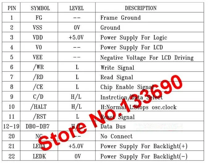
I see the datasheet for the and it say :
So I think is impossible :
Output voltage "H" VOH VDD-0.3 VDD V : pin DB0@DB7
VDD = 4.5v mini so 4.5-0.3 = 4.2v mini. :(
-
With the Max7219 chip you can built this :
The code I use :
#define DCSBIOS_IRQ_SERIAL
#include <DcsBios.h>
#include <LedControl.h>
unsigned long previousMillis = 0;
unsigned long currentMillis = millis();

// Arduino Pin 5 to DIN, 7 to Clk, 6 to LOAD, no.of devices is 1
LedControl lc=LedControl(5,7,6,1);


void setup()
{
 DcsBios::setup();
// Initialize the MAX7219 device
 lc.shutdown(0,false);   // Enable display
 lc.setIntensity(0,5);  // Set brightness level (0 is min, 15 is max)
 lc.clearDisplay(0);     // Clear display register

}

DcsBios::Switch2Pos eppApuGenPwr("EPP_APU_GEN_PWR", 10);


void onMasterCautionChange(unsigned int newValue)
 {
   if (newValue==1)
   {
   previousMillis = currentMillis;
   }
 }

DcsBios::IntegerBuffer masterCautionBuffer(0x1012, 0x0800, 11, onMasterCautionChange);


void loop()
 {
 currentMillis = millis();

 if (currentMillis - previousMillis < 400)
   {
   lc.setRow(0,7,B01110110);
   lc.setRow(0,6,B01110111);
   lc.setRow(0,5,B01011011);
   lc.setRow(0,4,B00001111);
   lc.setRow(0,3,B01001111);
   lc.setRow(0,2,B00000101);
   lc.setRow(0,1,B10000000);
   lc.setRow(0,0,B01001110);
   }

 else
   {
   lc.setRow(0,7,B01011011);
   lc.setRow(0,6,B00111011);
   lc.setRow(0,5,B11011011);
   lc.setRow(0,4,B00000000);
   lc.setRow(0,3,B01111110);
   lc.setRow(0,2,B01010111);
   lc.setRow(0,1,B00000000);
   lc.setRow(0,0,B00000000);
   }

   DcsBios::loop();

}
The important part is :
#include <LedControl.h>
LedControl lc=LedControl(5,7,6,1); // Arduino Pin 5 to DIN, 7 to Clk, 6 to LOAD, no.of devices is 1
lc.shutdown(0,false); // Enable display
lc.setIntensity(0,5); // Set brightness level (0 is min, 15 is max)
lc.clearDisplay(0); // Clear display register
lc.setRow is for controling every segment but there are others command like this.
lc.setDigit
lc.setLed
lc.setChar
etc..
-
Wow, perfect, I want to do a cockpit like that. Compact but functional. Great work!
-
Hoo RS485 is already included in dcs bios, perfect! I found the RS485 exemple, thanks!
Using a PC power supply is a good idea.
I read for powering Arduino is :
5v by USB port
6-20V (7-12v better) by the Vin pin or the jack. (not 5v cause Arduino do a -1v, drop of tension by this way)
So, how can I send 5v by the 5v pin? It's not a 5v out?
Else, If I powering all arduino with the 5v, so the 12v no use at all?
Thanks again!
-
Adafruit 3.5” TFT LCD is a closer match. I’d recommend lighted push buttons or a taller non lighted one so you could insert a lighting strip underneath.
Ok thanks a lot for your precision.
Ian;3280781']For driving a TFT display for the CDU over a SPI interface' date=' I'd look into Arduino-compatible boards with an ARM processor. An ATMega328 can drive one, but you'll get a lot of lag when it has to push lots of pixels on a full display update (e.g. when switching to another page).[/quote']And the Arduino Due (or Zero) is not more powerfull for this?
-
Is there a thread who explain the code we need for the rs485 lan?
I see this :
#define DCSBIOS_RS485_SLAVE XX
For the slave, but I don't find what I must write for the master.
Any help?
And so, I need 2/3 Mega 2560 Pro for RS485 Master:
And, X unit of 2560 Pro MINI and Micro for Slave :
Right?
A 12v transformer with 3A, it's enough to power everything (all arduino board)?
Thanks a lot!
-
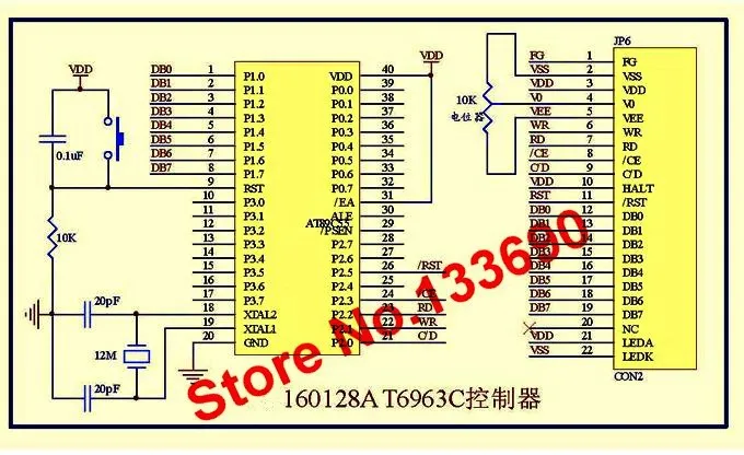
I found this (orange.. no green lcd ):
160 * 128 dots orange (black background).
I think it work with arduino and dcs bios?
Why I want to use a LCD on arduino? Because with the LCD 5" the writing font is affected by the anti aliasing and it's not very clear. And the backlight of the 5" LCD (TFT) is bad (too shinny, etc...)
-
Hi
I have a 5" hdmi screen (216*160mm visible) and I want to use it for the CDU.
But, there's another best way?
I mean the 5" screen is a TFT LCD and have not a real black background coz angles, like this :
http://cdn2.ubergizmo.com/wp-content/uploads/2016/06/tft-vs-ips-view-angle.jpg
So, is there any other solution like a screen with only green dot/led or other?
If not, I have this screen :
I think I can't connect it to an Arduino, right?
And for keayboard, I think this buttons are great?
Thanks a lot!
-
It works!
Thanks for your help!
It's not a clear code, but it's better than nothing.
#define DCSBIOS_IRQ_SERIAL #include <DcsBios.h> #include <LedControl.h> unsigned long previousMillis = 0; unsigned long currentMillis = millis(); // Arduino Pin 5 to DIN, 7 to Clk, 6 to LOAD, no.of devices is 1 LedControl lc=LedControl(5,7,6,1); void setup() { DcsBios::setup(); // Initialize the MAX7219 device lc.shutdown(0,false); // Enable display lc.setIntensity(0,5); // Set brightness level (0 is min, 15 is max) lc.clearDisplay(0); // Clear display register } DcsBios::Switch2Pos eppApuGenPwr("EPP_APU_GEN_PWR", 10); void onMasterCautionChange(unsigned int newValue) { if (newValue==1) { previousMillis = currentMillis; } } DcsBios::IntegerBuffer masterCautionBuffer(0x1012, 0x0800, 11, onMasterCautionChange); void loop() { currentMillis = millis(); if (currentMillis - previousMillis < 400) { lc.setRow(0,7,B01110110); lc.setRow(0,6,B01110111); lc.setRow(0,5,B01011011); lc.setRow(0,4,B00001111); lc.setRow(0,3,B01001111); lc.setRow(0,2,B00000101); lc.setRow(0,1,B10000000); lc.setRow(0,0,B01001110); } else { lc.setRow(0,7,B01011011); lc.setRow(0,6,B00111011); lc.setRow(0,5,B11011011); lc.setRow(0,4,B00000000); lc.setRow(0,3,B01111110); lc.setRow(0,2,B01010111); lc.setRow(0,1,B00000000); lc.setRow(0,0,B00000000); } DcsBios::loop(); } -
Ian;3278662']If I understand correctly' date=' you want to show a steady text while the master caution light is blinking and nothing when it is shut off..[/quote']
Yes that's it! Thanks a lot for your explanation. I do this, this week. :book:
-
This is not my question, I want to do some things like a text with a 7-segment when the Master Caution is on, if possible.
-
Hi,
I was makking a 7-segment for the Master Caution.
But, I have only found the Master Caution LED and the 7-segment twinkle:
How can I do, to run a code then Master Caution is active? (not the LED but the Master Caution itself).
I want to showing the Master Caution all the time among other things.
Any idea? Thanks!:thumbup:
-
I want to showing the Master Caution all the time (or another CODE when the Master Caution is active) on my 7-segment indeed. :smartass:
I make a new thread for that.
-
Thanks for reply.
The
DcsBios::Switch2Pos ufcMasterCaution("UFC_MASTER_CAUTION", PIN);Is only when I push the Master Caution reset button, no?
I have trying with this code and It work (LCD 7 segment) only if I push the reset button.
-
Hi guys!
DCS Bios is very perfect for me, but is there a command line for the Master Caution? (not the led!)
Cause this :
void onMasterCautionChange(unsigned int newValue) {
/* your code here */
}
DcsBios::IntegerBuffer masterCautionBuffer(0x1012, 0x0800, 11, onMasterCautionChange);
It's work only if the LED (ingame) is ON, so the code inside "twinkle" like this :
I want a code who works all the time then the Master Caution (the fonction, not the led) is ON.
Any idea? Thanks a lot!
Ps: I'm noob with C and programmation.
-
Is it possible to export this to an android device or a second PC with Windows?
Thanks, great job :)
-
Indeed... Thanks for the information :)


Tobii 4C and DCS 2.5
in PC Hardware and Related Software
Posted
Hello, do you have found a solution for this? It works now? Thanks a lot.