Oakes
-
Posts
219 -
Joined
-
Last visited
-
Days Won
1
Content Type
Profiles
Forums
Events
Everything posted by Oakes
-
Tried both option, no change. I meant this from Ready as a way to fix the problem without restarting VA. Did some further testing, with version 25 and 26 I have the issue, with version 24 the issue is gone. To test I only replaced the viacom .dll in the VA plugin folder. No other changes where made.
-
Hi all I have the same problem. I can reliably reproduce the problem by rotating the radio switch (fwd, down, back and so) on the warthog quickly => this generates Transmit/Release TX1, 2,3 etc and very quickly the PTT is reversed. The red part seems to induce the problem. Further, I cannot reverse the inverted behavior by continuing to rotate the com switch, I can however reverse the inverted behavior by rapidly pushing 1,2,3 on the keyboard. VC 2.5.26.4 / VA 1.8.9 In the meantime, how do I bind Viacom Reset to a Button? /Oakes 11:39:43.341 Listening resumed 11:39:43.313 Joystick : 'Transmit TX1 release' 11:39:40.728 Listening suspended 11:39:40.690 Joystick : 'Transmit TX1 press' 11:39:31.094 Listening resumed 11:39:31.065 Joystick : 'Transmit TX2 release' 11:39:31.056 Listening suspended 11:39:31.021 Joystick : 'Transmit TX2 press' 11:39:30.988 Listening resumed 11:39:30.954 Joystick : 'Transmit TX3 release' 11:39:30.908 Listening suspended 11:39:30.867 Joystick : 'Transmit TX3 press' 11:39:30.861 Joystick : 'Transmit TX2 release' 11:39:30.797 Listening resumed 11:39:30.769 Joystick : 'Transmit TX2 press' 11:39:29.160 Listening suspended 11:39:29.128 Joystick : 'Transmit TX1 release' 11:39:28.845 Listening resumed 11:39:28.613 Joystick : 'Transmit TX1 press' 11:39:27.273 Plugin 'VAICOM PRO for DCS World' initialized. 11:39:27.265 Ready for commands. 11:39:27.252 Listening suspended 11:39:26.382 Nahimic app detected. This may cause conflicts with VoiceAttack. This warning can be turned off via the Options screen. 11:39:26.334 Initializing.. 11:39:26.334 Press LCtrl+LAlt+C for config. 11:39:26.334 VAICOM PRO for DCS World. License: PRO 11:39:25.924 Plugin support enabled.
-
TM Warthog/MFD Layout Tool + Vector Templates
Oakes replied to Oakes's topic in PC Hardware and Related Software
Hi all New version out. See top post. You can now autogenerate layout files. /Oakes -
TM Warthog/MFD Layout Tool + Vector Templates
Oakes replied to Oakes's topic in PC Hardware and Related Software
hi sobe Aha...excel has probably added those " characters, no worries. You can see these if you open up the cvs file with notepad. EFFL UP (1) 16 Briefing won't show up because there is no matching tag in the svg templates. The script is only doing "search and replace" in the template files, if it cant find the tag nothing will happen. You need to edit the .svg files in the Templates folder (with Inkscape) in order to add the tag. Attached are files for the TMWarthog with bigger fonts (I had to split this up into 4 parts to fit the bigger font). Unpack these into the Templates folder and run the script again. /Oakes bigfont.zip -
TM Warthog/MFD Layout Tool + Vector Templates
Oakes replied to Oakes's topic in PC Hardware and Related Software
hi sobe Good job breaking the script :) Turns out, SVG/XML doesn't like &"<> => CMS UP,15,P5 1&1x2 or CHAFF breaks the generated SVG file. Fixed in v 1.02 btw, you have some " in your comments in the F18 cvs file, doesn't matter since they are in the comments (#) but it is still odd that they are there. Which program do you use to edit the files? I suggest using a text editor like notepad or notepad++ for editing. /Oakes -
TM Warthog/MFD Layout Tool + Vector Templates
Oakes replied to Oakes's topic in PC Hardware and Related Software
Hi mate Updated version above with USLetter (8.5x11 inch) templates. TMWH_SK_USLetter.SVG and TMWH_THR_USLetter.SVG are the ones you need. I also added templates + tags etc for MFD3 and 4 Note: I haven't changed any code to add this, only added templates with the correct tags + added the same tags to the .cvs files. /Oakes -
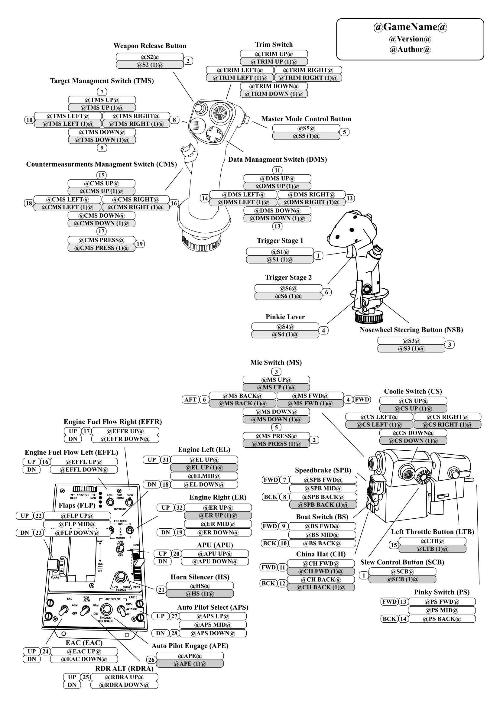
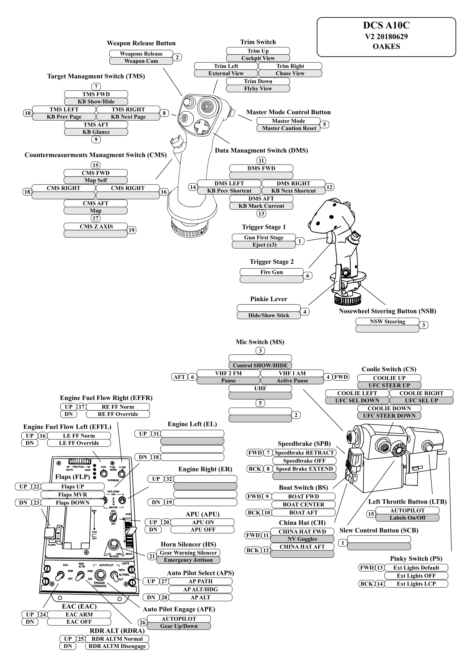
Hi all I wrote a little tool in AHK to generate SVG layout charts for the TM Warthog and F16 MFD:s. The tool takes a .csv file in which the key mappings are defined and generates several SVG files in different formats from a set of templates. NEW in V2: Added a script to autogenerate key map definition files from DCS via the exported HTML key mapping files. Do you bindings in DCS, export the bindings as HTML and run the scripts andyou will have a nice layout in about 2 min. All the graphics are vectors => you can scale as much as you like without any loss in quality. If you change a binding, simply update the .csv file and generate an updated set of SVG. The SVG:s are generated from templates that you can change the layout in if you like, or you can make you own templates for other joysticks/controllers. /Oakes -------------------------- Readme.txt Version history 1_00 Initial Release 1_01 Added US size templates Added MFD 3 and 4 Templates Added MFD 3 and 4 tags to TMWH_F16MFD_Template_v1_01.csv Added MFD 3 and 4 tags to Example_DCSA10C_v2_01.csv 1_02 Fix for XML/SVG escaped characters ( &"<> ) V2_00 Added a script to autogenerate definition files from DCS exported HTML files. Added several new templates. Code cleanup Readme: To run the scrips, either run the .exe or download and install AutoHotkey from https://www.autohotkey.com/ and run the .ahk files. --------------------------------------------------------------------------------------- ---GenerateLayout_vx_xx (.ahk or .exe)--- --------------------------------------------------------------------------------------- This script will ask for a .csv file that contains the keywords to replace for the .svg files in the folder /scriptroot/Templates_Sorted. The script will then create a new folder in the script folder and name it according to the "GameName" tag in the .cvs file. The script will then generate .svg files into the “GameName” folder based on the .svg templates found in the Templates_Sorted folder. The generated files will mirror the folder structure in Templates_Sorted folder. You can rearrange templates/folders and/or add or delete templates to suit you needs. You can as an example remove all the US sized templates if you use A3/A4 sizes. In the generated files the @something@ tags in the template *.svg files will be replaced with the matching entry in the .cvs file. Currently there are templates for the Thrustmaster Warthog and the Thrustmaster F16 MFD's I've included two examples .cvs file for the DCS A10C and X4 (DCSA10C_Demo_A.cvs and X4.cvs) in the Defintion Files folder. Try running them as per the instructions below to generate layouts for the Warthog. ----------------------------------------------------------------------------- Usage: 1. Extract the files to a suitable folder. 2. Create a definition.csv file with your button assignments in the format detailed below. You can use the included .cvs template as a start (Template_TMWH_4MFD.csv). You can leave any entry blank if you don't have the hardware or haven't assigned the button within the game. 3. Run GenerateLayout_vx_xx (.ahk or .exe). 4. Select the .cvs you created. Previously generated SVG layouts will be overwritten. 5. Wait for the message "Done etc". 6. Open the Layouts"GameName" folder and open the desired svg file, print etc Included files are in A4, A3, Letter and Tabloid formats + MFD Inserts + 3:4 format usable as a KneeBoard plate in DCS (KB in the filename/directory). For Kneeboard you need to save/convert the svg. to jpeg. ----------------------------------------------------------------------------- CVS format: [svg tag],[button number],[replace svg tag with this] ----------------------------------------------------------------------------- Example, the line: S1,1,Gun First Stage Tells GenerateLayout_vx_xx (.ahk or .exe) to replace the @S1@ tag with "Gun First Stage" in all the template svg:s when generating a corresponding .svg files in the "GameName" folder. ----------------------------------------------------------------------------- The (1) and (2) suffix in the tags denotes shifted buttons (by using a modifier in DCS or TARGET) In order for the script to work the .csv file needs the following entries (at a minimum) GameName,,[gamename] Use # for comments The [button number] is not currently used by the GenerateLayout_vx_xx script, but is included as a convenient way to match the game mapping (since games generally only tell you the DX button number) to the .cvs file. You can leave this blank if you do your own files etc, example below: S1,,Gun First Stage S1,1,Gun First Stage are both valid CSV files. Note: The [button number] is used by the DCSMapper script to auto-generate definition files by exporting the DCS mappings to html (this is done within DCS under controls). See more below. ---------------------------------------------------------------------- ---Custom SVG files--- Size, layout etc can be changed in the included templates. All the graphics have been converted to vector format and can be scaled freely without loss of quality. You can make you own layout templates for other joysticks / controllers etc I use Inkscape for svg work. --------------------------------------------------------------------------------------- ---FindTags_vx_xx (.ahk or .exe)--- --------------------------------------------------------------------------------------- This script will look through a folder with .svg files to find all the @something@ tags in the files. Output is a file called tags.txt. Use this to as a helper generate a list of tags if you make you own .svg files for other joysticks/controllers or if you add tags to the included svg files. --------------------------------------------------------------------------------------- ---DCSMapper_vx_xx (.ahk or .exe)--- --------------------------------------------------------------------------------------- DCSMapper will create a definition file from the exported key bindings in DCS. Usage: 1. First, start DCS and do all the bindings you need, including any modifiers. 2. Under controls click the "Make HTML" and save the file/files to a folder. 3. Copy the Template_TMWH_4MFD.csv to a suitable location and rename it. Example: DCSA10C_V1.csv (example file located in \Definition Files\DCS) 4. Open the renamed definition file in Notepad or similar and change: a) [GameName], this can be anything, ex DCS_A10C b) Add any modifiers that you have used when binding "Modifier,[modifier number],[modifier button] [modifier number] corresponds to the number in parenthesis in the definition files. [modifier button] is the button used as a modifier in DCS. Example, you use JOY_BTN 4 as a modifier nbr 1, and when you press both the modifier and the Master Mode Control Button on the Warthog Stick (aka button S5 or DX 5) you go to the Weapon View. This will look like this in the exported HTML for the :´ "JOY_BTN4 - JOY_BTN5" F6 Released weapon view View DCSMapper will detect this when going through the exported HTML file and write the line "S5 (1),5,Weapon view" in the generated definition file. 5. Save the file. 6. Run DCSMapper and select the renamed definition file. Example: DCSA10C_V1.csv (example file located in \Definition Files\DCS). 7. Select the folder where you saved the exported HTML files. Example: \DCS Exported Keybinds\A-10CKEYMAPS\A-10C_2019_05_23 8. DCSMapper will now go through the selected definition file and the exported HTML files and map the bindings in the HTML files into a copy of the definition file. The new definition file has the same name as the file picked in step 6 but with the suffix "A" added to the end of the filename. The new definition file is in the same directory as the file picked in step 6. Example: DCSA10C_V1_A.csv (example file located in \Definition Files\DCS) 9. Run GenerateLayout_vx_xx and select the file generated in step 8. Example: DCSA10C_V1_A.csv (example file located in \Definition Files\DCS) Note: You can use -IGNORE- to stop DCSMapper adding the binding from the exported HTML file. Example EAC UP,24,,-IGNORE- I've included my own .cvs definition file and exported HTML for the DCS A10C as an example. Try running it (by following as per the instructions above to generate layoutsfor the Warthog. ------------------------------------------------------------------------- Example .cvs file (excerpt): #,, #,, Instructions: Replace text within [] with the appropriate info/button etc #,, #,, # Details,, #,, GameName,,DCS A10C Version,,V1 Author,,Oakes #,, # ----------------Modifiers (for DCSMapper only)---------------------,, #,, Modifiers can be used with DCS Mapper to auto-generate #,, definition files. Put the name of the buttons you use as #,, modifiers in DCS here. Check the exported html file for the correct #,, name. #,, Modifier,1,JOY_BTN4 Modifier,2,JOY_BTN3 #,, ..... #,, Modifier,[x],JOY_BTN[x] #,, # ----------------------------Stick-------------------------------,, #,, #,, For DCSMapperOnly. KeyMapFile tells DCSMapper where to look for #,, Modifiers can be used with DCS Mapper to auto-generate the mappings #,, made in DCS for the specific device. Do not use .html to the end of the file name. #,, KeyMapFile,Joystick - HOTAS Warthog {D8CE4CE0-2963-11e8-8001-444553540000} #,, #,, #,, Button Format #,, [tag],[button Nbr (used for auto mappers like DCS Mapper)],[replacement text] #,, #,, Example: S2,2,Weapon release will replace all instances of the text "@S2@" with #,, the text "Weapons release" for all the .SVG files in the Templates directory. #,, #,, # ---Stick Buttons---,, #,, #,, # Trigger Stage 1,, #,, S1,1,Gun First Stage S1 (1),1, S1 (2),1, #,, # Weapon Release Button,, #,, S2,2,Weapon release S2 (1),2,Weapon release S2 (2),2,Weapon release #,, # Nosewheel Steering Button - NSB,, #,, S3,3,NWS/Lase S3 (1),3, S3 (2),3, #,, # Pinkie Lever,, #,, S4,4,LAAP Engage/Disengage S4 (1),4, S4 (2),4,Time normal #,, # Master Mode Control Button,, #,, S5,5,Cycle Master Mode S5 (1),5,Weapon view S5 (2),5,WPN to TGT View #,, # Trigger Stage 2,, #,, S6,6,Gun Second Stage S6 (1),6, S6 (2),6, Readme_V2.txt GL_DCSMap_Release_V2.rar

-
Hi all Just a couple of pictures of my custom-built ball-bearing gimbal. It is somewhat oversized/over-engineered :-), but works very well from a functional standpoint, can't go back to a normal stick now. The extra length really helps with precision but the real kicker for me is that when the stick is at the stops I can still easily push the buttons etc (since the angle of the stick versus the hand is only about 15 deg vs mabye 40 deg for a standard length joystick), much more comfortable. For USB I used one of Leo Bodnar's cards, the handle is still connected to the warthog base so I can use target etc. To detect the x and y position I used 90deg hall effect rotary sensors. The small arm to which the spring attaches to makes is very easy to adjust the center position. The stops can be slid up/down to adjust the travel. Camera went a little bonkers on the second and third image and made everything into black and white, don't know why, maybe the camera was feeling depressed and neglected since we use our phone cameras almost exclusively these days.....:D /Oakes
-
I wish I had the time....full-time job + two kids:helpsmilie: Special tools are really not needed though, you can do this mod with a drill and a file. You need an USB hub, no room internally in the throttle though => my throttle now has two USB cables. USB is a host-controlled bus interface, there can only be one host per bus...so this won't work. /Oakes
-
Hi all I finally broke down and decided to fix the Warthog Slew thingy. I understand that they tried to save a bit on the BOM cost but...:doh: Final result: Complete imgur album: Warthog Slew Replacement If you’re interested in the CNC I used for this mod, here are some really old videos of it in use: Youtube Below is a short guide, intended more as inspiration rather than an complete step by step guide on how to do this, be warned if you intend to do this you need to be able to read a wiring diagram, solder, manufacture a few parts out of plastic, calibrate the joystick in windows etc. On the plus side, if you are careful while doing the mod everything is reversible. Parts used: I used an ALPS type mini analogue joystick that I had bought several years earlier for another project (collective build for DCS:BS - ). Part no is RKJXP1224002, it seems that this part is end-of-life but I could find it in stock on eBay and Conrad + other various places. This part might also work: RKJXK1210002. When buying the joystick make sure that the diagonal dimensions of the square joystick metal housing are somewhat bigger than the diameter of the mounting hole. This is what’s keeping the joystick from going through the mounting hole from behind. A matching thumb-stick. I made my own on my CNC machine, but these should be available on ebay etc. A BU0836A USB Joystick controller from Leo Bodnar: BU0836A Some 5 wire thin cable, I used an old PS/2 extension cable I had laying around, a ribbon cable should work although I was a little bit worried about electrical noise from the rest of the joystick interfering with the analog signal so I wanted a shielded cable. You will also need a USB cable suitable for the connection between the USB controller and the computer. Some plastic sheet from 1.5 to 2.5 mm thick Glue etc The Mod: Ok, first thing is to get the original slew control out of the frame with an appropriate tool for the job ;) On second thought, don't use that tool, google a nice guide on how to disassembly the warthog throttle. In order to do this mod the same way I did it you need to drill out 4 pop rivets on the front of the throttle, however other than everything else is screwed together and it comes apart rather nicely. Since there is limited space in the throttle handle the idea was to fix the mini joystick in place without building an outer housing for the mini joystick matching the dimensions of the original slew control. In order to do this I made a face plate in 1.5 mm thick plastic that matches the dimensions of the mounting hole for the slew controller, make sure you include the little guide tab on the face plate. The face-plate will center the joystick in the hole and the metal housing will rest directly on the throttle handle plastic on the back of the mounting hole and thus preventing the joystick from going through the hole. I made the face plate on my CNC machine but it should be fairly easy to do this with scissors, a drill and a file etc. The hole in the middle of the face plate needs to be big enough so that it doesn’t interfere with the movement of the joystick shaft (including the thumb-stick that mounts on the joystick shaft). I also made a little center plate on the CNC, this plate was used to center the face plate on the mini-joystick while gluing the face plate to the mini-joystick. It is not needed but makes it easier to center the face-plate on the joystick. Face-plate to the upper left, centering plate lower middle, sliding fixture plate on the upper right: I scuffed the surfaces of the face plate and joystick housing with sandpaper, cleaned with a little alcohol and then used gap-filling super glue to attached the face-plate to the joystick. Make sure you mount the face-plate with the guide tab in line with the y axle on the mini joystick (as seen on the pictures) => this will make the joystick axles line up with the vertical and horizontal. The button switch on the side of the joystick should be to the left of the joystick when the guide tab is facing up (otherwise you will run into clearance problems later). Face-plate + centering plate: Face-plate orientation: Test Fit: My original plan to hold the joystick in place was to glue it to the throttle handle but I decided that it would be beneficial to be able to easily remove/replace the joystick at a later stage. Hot-glue might have worked now that I think about it…. With the faceplate in place the joystick cannot go forwards through the mounting hole in the throttle (the metal housing is bigger than the hole), but it can be pushed back into the throttle => we need something on the back to stop this from happening. The angle between the back of the joystick and the inner side-plate is not 90 degrees => we can use a sliding plate on a 5mm (M3) hex spacer mounted to the side-plate to push on the back of the mini joystick. Two fixture plates + washers etc pushing on the back of the joystick As you can see in the above picture, the further I push the slide-plates down on the hex spacer by tightening the M3 hex bolt the more force the plate exerts on the back of the joystick. The washers and the M6 nut also slides on the hex spacer (internal dimension is bigger that the spacer). Note that one of the slide-plates is slightly shorter than the other to account for the angle. Side-plate + fixture plates + washers etc When drilling the hole for the hex-spacer make sure you leave enough room for the sliding plate, aim for about 4-5mm distance between the hex-spacer and the centre of the joystick back plate. Add washers to both sides of the side-plate to stabilize the hex spacer. The side plate is made from reinforced plastic => I had some trouble with the drill wandering => use a drill press and a sharp drill if you have one (I do but I was lazy). Cables Next step is to make the cable that goes between the mini-joystick and the USB Controller card in the base of the throttle, if you haven’t done so by know you now need to remove the left throttle assembly from the base. I wasn’t able to fit the new joystick cable + the original cable in the channel => I had to remove the heatshrink from the original cable + remove the plastic insulation from the new cable, carefully taping both together in a flat configuration as seen on the picture below. To keep the shielding intact I also had to manually rewrap the strands of the new cable with shielding taken from the PS/2 cable. Make sure you leave plenty of cable in both ends to reach the joystick and USB controller card. The combined cables The combined cables in the channel Now solder the cables to the mini joystick, use heat shrink etc to protect the connection (or hot glue). Refer to the diagrams on Leo’s site for the correct connections. Make sure you leave room for the hex+ slide plates etc. In general you need: Ground +5VDC X Y Button connected to the joystick, ground and +5VDC goes to the outside of the pots and X and Y in the middle. If this is new to you I suggest you connect the USB Controller to your PC and experiment with this before you solder the wires to the joystick. Remember to leave some slack in the cable, you will need to route it around the other hardware in the throttle handle + also remember to connect the cable shield only to ground in one end of the cable (I used the ground on the USB Controller card). Solder done: Now it is time to reassemble the throttle handle, you will need to mount the mini-joystick, attach the various connectors etc to the PCB in the handle and then finally re-attach the side-plates. I left the original slew controller connected and hidden inside the handle (maybe not necessary but doesn’t hurt). I had some interference between the new thumbs stick and the 4-way switch on the handle front => I removed the shaft of the 4-way and turned it down about 4 mm (diameter) in the spindle of the CNC. Turned down 4 way switch: To get the new USB cable out of the throttle base I drilled the pop rivets and removed the front metal plate, made an appropriately sized indentation in the plastic. Remember to use a cable tie as strain relief. New USB cable: Put the throttle handle back on the throttle base and connect the new cable to the USB controller card. I placed the USB card in a ESD bag to protect it from short circuits and simply wedged it into a suitable spot (I removed the 3 pcs of steel plate attached to the bottom of the throttle to create some extra space). Note the cable tie holding the joystick cable to the back left mounting post. Routing: Put the bottom plate back on the throttle, connect the USB to the PC, calibrate and you’re done. The mechanical dead-zone on the joystick I used is rather large => I need about 10% deadzone. I might replace the joystick at a later date if I find this to be a problem. /brds Oakes
-
Hi mate Inform us...........:pilotfly: And good luck.... /Oakes
-
Hi Jocman Sorry for being so quiet lately, some other stuff (good stuff) has taken priority in my life right now. Anyways, the code we tried earlier should work very well for this. http://forums.eagle.ru/showpost.php?p=1061261&postcount=125 You do need to change the name of the function, otherwise it wont work. /Oakes
-
Hi Cezar {[10] = {TwoPositionSwitch, 60, 2, 1} 60 is the device number and 2 is the button number on the device that we want to change. So thin of 60,2 as the "adress" of the button you want to change. Devices are specified in the Devices.lua file and button numbers in clickableData.lua. So if you want to change a button/switch you first find the button/switch in clickableData.lua (below is the relevant line for the "K-041 Targeting-navigation system power switch"). elements["K-041-PTR"] = { class = {class_type.TUMB,class_type.TUMB}, hint = LOCALIZE("K-041 Targeting-navigation system power switch"), device = [color=Red]devices.K041[/color], action={device_commands.Button_[color=Lime]2[/color],device_commands.Button_2}, arg = {433,433}, arg_value = {-direction*1.0,direction*1.0}, arg_lim = {{0.0, 1.0},{0.0, 1.0}}, use_OBB = true, updatable = true}Then you check devices.lua for the device number of devices.K041, you will find that devices.K041 = 60. Here is a helpful compilation of all the buttons and their device and button numbers. http://forums.eagle.ru/showpost.php?p=764486&postcount=30 Also have a look here: http://forums.eagle.ru/showpost.php?p=1049142&postcount=114 /Oakes
-
Hi mate Unfortunately it is a little bit more complicated than that. The OC cards will not show up as HID buttons in DCS, you need to work with Export.lua etc to get this to work. Sort of a tutorial: Please see this thread, starts at post 53 (discussions between Stelios and me) http://forums.eagle.ru/showthread.php?t=45071&page=6 /Oakes
-
TM:WH preprogramed with deadzone from factory?
Oakes replied to Oakes's topic in PC Hardware and Related Software
Thanks for the update, works like a charm. No more deadzone = me happy:thumbup: /Oakes -
Hi Jocman Yes, changing the pins will work as well. I don't know about the 9+ encoders, but at first glance it seems like one shouldn't connect two GND pins togheter..... /Oakes
-
Hi Jocman No, you need to choose one of the [20] = {Encoder, 30, 1, 0.018}/ [20] = {Encoder, 30, 1, -0.018} lines to put into your siocConfig file. The "-" sign will just reverse the rotation if needed. When I connected my rotary and turned it clockwise the virtual rotary turned anti-clockwise so I need to reverse this => I added a "-" sign in front of the 0.018. /Oakes
-
Hi mate Ok, I've had a look at this now. Turns out, you need to send + or - to the device to move the rotary, +0.018 to go 1 degree positive and -0.018 to go 1 degree negative. This code should do the trick: function Encoder(pValue, pDevice, pNumber, pTick) if pValue ~= 0 then calcValue = round(pTick * pValue,3) GetDevice(pDevice):performClickableAction(pNumber + 3000,round(pTick * pValue,3)) end endand [20] = {Encoder, 30, 1, 0.018},or [20] = {Encoder, 30, 1, -0.018},depending on which way you want the encoder to turn. You also need to replace (this function did not support negative sioc values previously, changes are marked in red) the SIOC_Parse function in ExportSuppoart.lua to -- Used togheter with a for loop to extract Sioc parameters and their value from a string function SIOC_Parse(pSIOC_String) local i = -1 return function () i= string.find(pSIOC_String, ":",i+1) if i ~= nil then return tonumber(string.match(pSIOC_String, ":(%d+)=[color=Red][+-]?[/color]%d+",i)) , tonumber(string.match(pSIOC_String, ":%d+=([color=Red][+-]?[/color]%d+)",i)) end end endIn you SIOC file, remove the Rotate etc and just use the line: Var 0020, Link IOCARD_ENCODER, Input 34, Aceleration 1, Type 2How it works: Sioc will set var nbr 20 to +1 or -1 depending on which way we turn the encoder (and then reset var 20 back to 0). This varaible gets sent to our encoder function where we multiply it with 0.018 and send it of to DCS:BS => DCS:BS gets +0.018 or -0.018 depending on which way we turn the encoder. You can change the 0.018 value up or down to get a perfect match (1 encoder detent = degree), it is a little bit off now. There are some odd behavior when you change direction etc but we have the same behavior when we use the mouse wheel. /brds Oakes
-
Hi y2kiah I think we are building for DCS:BS not AC10 => io.write etc should work?...or..? /Oakes
-
Merry Christmas to you too... I'm stumped as to why this doesn't work....lets try some debugging.. function EncoderDebug(pValue, pDevice, pNumber, pMax, pDivide) local calcValue calcValue = round((pMax /pDivide) * pValue,3) io.write("Encoder debug.\nSIOC Value(pValue) ="..pValue.."\nCalculated value = "..calcValue.."\n") io.flush() GetDevice(pDevice):performClickableAction(pNumber + 3000,calcValue) endAdd the above code to your ExportSupport.lua file + change the [68] = {Encoder, 30, 1, 1, 359}to [68] = {EncoderDebug, 30, 1, 1, 359}This code will write debug info to the ./Temp/Export.log file in the DCS:BS main directory. You can open this file with notepad etc but I suggest you use a log viewer instead (a log viewer will monitor new entries to the file and display them immediately, notepad etc doesn't do this) http://www.kiwisyslog.com/kiwi-log-viewer-overview/ I suggest setting the encoder value to 180, start BS and then go a couple of steps up and then a couple of steps down and then check the log file. Are we sending the correct values to DSC:BS (i.e.. between 0 and 1)? Do the SIOC encoder value match the simulated value (we have assumed that SIOC Encoder value= 0 means that we should send 0 to BS, perhaps this is not correct? What happens when you go from 359 to 0 (or the other way around?) /Oakes
-
Just to confirm, you have a SIOC var (nbr 68 ) that is a value between 0 and 359 and when you turn the encoder one way this value increases and when you turn it the other way this value decreases? Could you post the SIOC code? /Oakes
-
Hi Jocman Well, the value send to DCS:BS should be between 0 and 1, the smallest increment is 0.001 => if we divide 1 with 359 and multiply with the incoming sioc value (which is 0 to 359) and round this value to 3 decimals we should be home. Sioc value is 0 => (1/359) * 0 = 0 Sioc value is 179 => (1/359) * 179 = 0.498 Sioc value is 359 => (1/359) * 359 = 1 This will give us 1 degree for each click of the encoder. Is that good enough resolution? Probably for a HSI but maybe not for the Abris cursor. function Encoder(pValue, pDevice, pNumber, pMax, pDivide) GetDevice(pDevice):performClickableAction(pNumber + 3000,round( ((pMax /pDivide) * pValue),3)) end and [123] = {Encoder, [color=Red]25, 1[/color], 1, 359}, Want more resolution? Make the sioc var go from 0 to 719 instead and [123] = {Encoder, [color=Red]25, 1[/color], 1, 719}, This is all untested (I'm at work:)) but give it a try. Red values need to match the device and button number. /Oakes
-
I got my TM:WH last week and spent the weekend mounting it to my gaming chair, nice to have a center stick instead of a side stick. Anyways, when checking out the stick response, jitter etc in DIView I noticed that the stick was at exactly 50% (X and Y position) i.e. dead center without any force on the stick (without widows calibration). My first thought was “Wow, perfectly calibrated from the factory and no jitter!...fantastic!!” Trouble is I can move the top of the stick about 0.5 to 1mm at the center without any response in DIView. However if I move the stick off center (say 10 degrees to the left) I can by adding a just slight pressure on the stick see a response (without any perceptible visual movement of the stick). The TM:WH design is essentially a gimbal mounted stick with a magnet on the end and a sensor that measures the movement of this magnet => unlike the Cougar there shouldn’t be any mechanical deadzone. The spring mechanism might develop some play etc due to wear and tear over the years but this shouldn’t (unlike the Cougar) introduce a mechanical deadzone which was an important selling point to me. Unfortunately, it seems to me that TM has added a (very) small center software deadzone when they do the factory calibration in order to achieve this “perfect center” straight out of the box. This, in my opinion creates, more problems than it solves. I do realize that this small deadzone might not have any importance in an actual sim, although my experience tells me that I don’t want any deadzone (mechanical or otherwise) around the center position when playing sims and secondly if I wanted one, I can easily add one in the TARGET software. I’ve been using this slightly:) moded Cougar stick for the last 5-6 years, it won’t return to exactly center (within 0.5% or so) when I let go of the stick but there is no need for a deadzone, in fact no center deadzone was one of the most important design requirements. Hall effect sensor take care of the jitter but as you can imagine it is a little hard to fit as a center mounted joystick:helpsmilie:. Anybody else have the same experience? Have I missed some setting in target etc? DIView software http://www.leobodnar.com/products/BU0836/DIView.zip /Oakes
-
Yep, you are correct, device is referring to the USBExp card, sorry for misleading you. I'm installing all my OC cards etc in a new rack box so I cant try this out myself right now, need a couple of more days. However, all is not lost, from the manual for the USBExp card: "INPUTS The inputs on the Master card are formed in groups of 9 + GND, this means that we have a total of 36 inputs on each input connector (J3 and J4), that is, for each Master card connected to the USBExpansion, we have 72 inputs, that multiplied by 4 cards on each USBExpansion, this means we have a total of 288 digital inputs, numbered as on the following table: [TABLE]Master card number|J3 inputs|J4 inputs 1|0 – 35|36 – 71 2|72 – 107|108 – 143 3|144 – 179|180 – 215 4|216 – 251|252 – 287[/TABLE]" Without trying this out myself I think that you only need one master line in the sioc.ini file (for the USBExp card) and then you refer to the inputs for the nbr 3 mastercard (meaning connected to J3 on the USBExp) as inputs 144 to 215. Secondly, from reading your earlier posts the above info might not be new to you (i.e use only one master line etc) but I'm not quite sure so I posted it anyway. I have a sneaky suspicion that are correct, masters need to be connected in series, otherwise, the unconnected parallel ports are electrically floating => lots of inputs on the port => USBExp led is on constantly => controlador goes nuts...etc /Oakes
-
Hi mate I think you need to put master=1,4,4,20 for the second master card, but I'm not sure, I've only used 1 master card so far. These might help: http://www.lekseecon.nl/sioc.html#mainwindow http://www.lekseecon.nl/howto.html#device /Oakes