VR FlightSim
-
Posts
65 -
Joined
-
Last visited
Content Type
Profiles
Forums
Events
Everything posted by VR FlightSim
-
Open Source Joystick FFB / DIY FFB Joystick
VR FlightSim replied to Berniyh's topic in PC Hardware and Related Software
@ MetalGear Honk Hey mate, long time no see:) Have you made any progress with your arduino? Jay -
Open Source Joystick FFB / DIY FFB Joystick
VR FlightSim replied to Berniyh's topic in PC Hardware and Related Software
Hey Michael My testing motor just arrived:D It is a weaker and cheaper brother of the 150W version intended for my design but even this one (120W) has one hell of a torque:thumbup: Now just waiting for the pulleyes.. Well I really appreciate your enthusiasm so here's something for you. This link http://a360.co/2zwBePp will take you to the project site where you can inspect the latest version of the model, take it apart, measure components, etc. Please be aware that the model hierarchy is total mess. It's a work in progress though. I don't know if you saw this but I've done simple model for short throw FFB gimball already. (smaller device for side pedestal or desktop) You can also download this model via the link in "description" section of the video here: Don't worry about the shipping cost, I would obviously cover that plus something for your work and material too. Jay -
Open Source Joystick FFB / DIY FFB Joystick
VR FlightSim replied to Berniyh's topic in PC Hardware and Related Software
Thanks Drakoz Prototyping the parts would be enormous help, however before we start cutting precious aluminium, need to make sure the gear ratio vs torque vs inertial factor are correct. Also cogging from belts and the motor it self needs to be as low as possible. I'm gonna test all this on a simple timber frame (one axis only), by powering up the motor in one direction and feel the result at the end of the stick.:joystick: I have ordered the pulleys and DC motor (same as in my cad model) for this purpose but it will take up to four weeks to deliver. Are you familiar with Fusion360? Regarding electronics, OS-CL (open source-control loading) dedicated motor drive circuit would be THE BEST possible solution but it is a huge challenge though. Jay -
Open Source Joystick FFB / DIY FFB Joystick
VR FlightSim replied to Berniyh's topic in PC Hardware and Related Software
I gave up my workshop when we moved house so I'm not able to do the machining my self at the moment. I want to get few quotes on these parts being manufactured by "professionals" but first I'm gonna knock up simple prototype of the geared part to ensure my ratio calculation are spot on. as mentioned earlier, anybody in UK with decent metal shop? :helpsmilie: Jay -
Open Source Joystick FFB / DIY FFB Joystick
VR FlightSim replied to Berniyh's topic in PC Hardware and Related Software
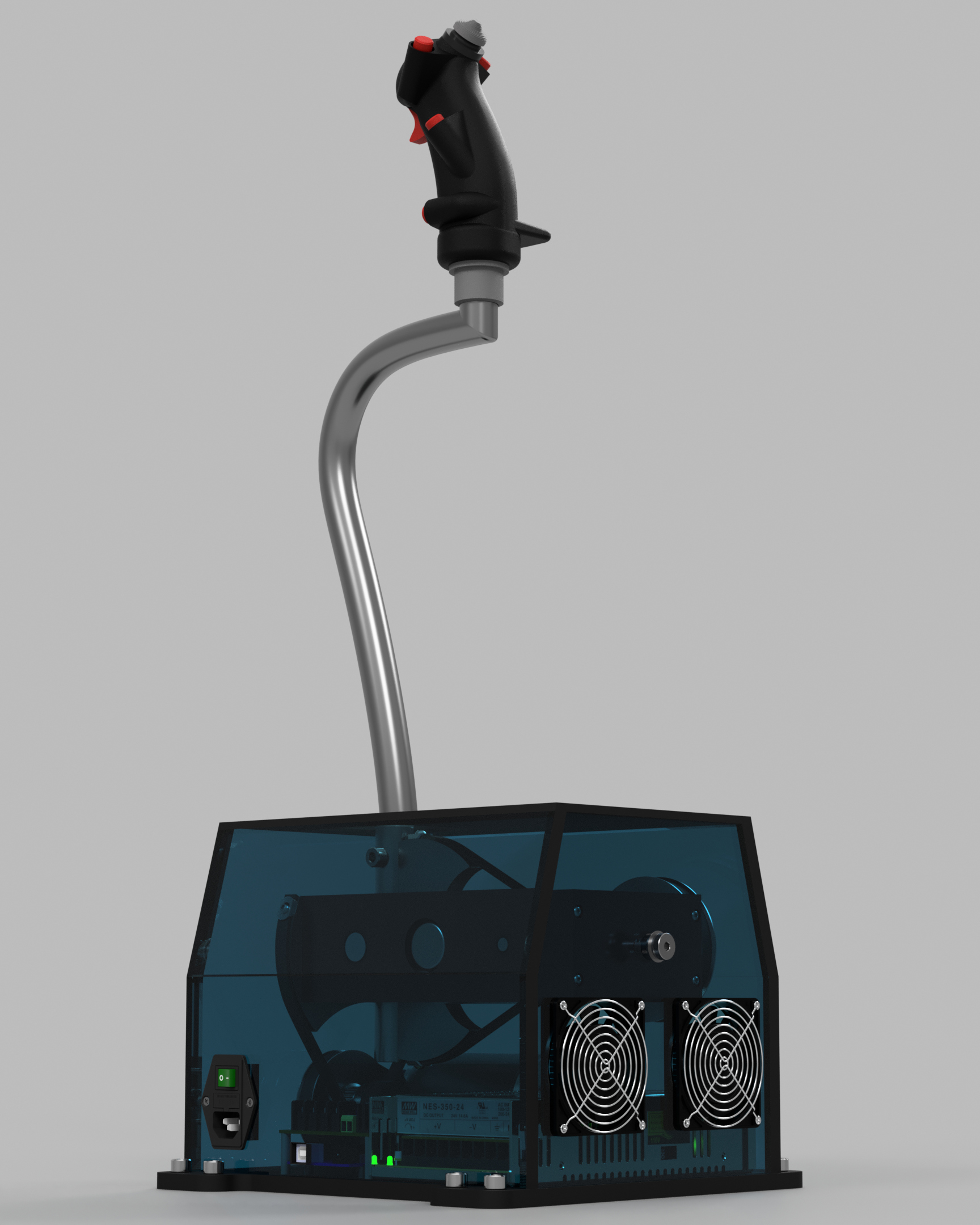
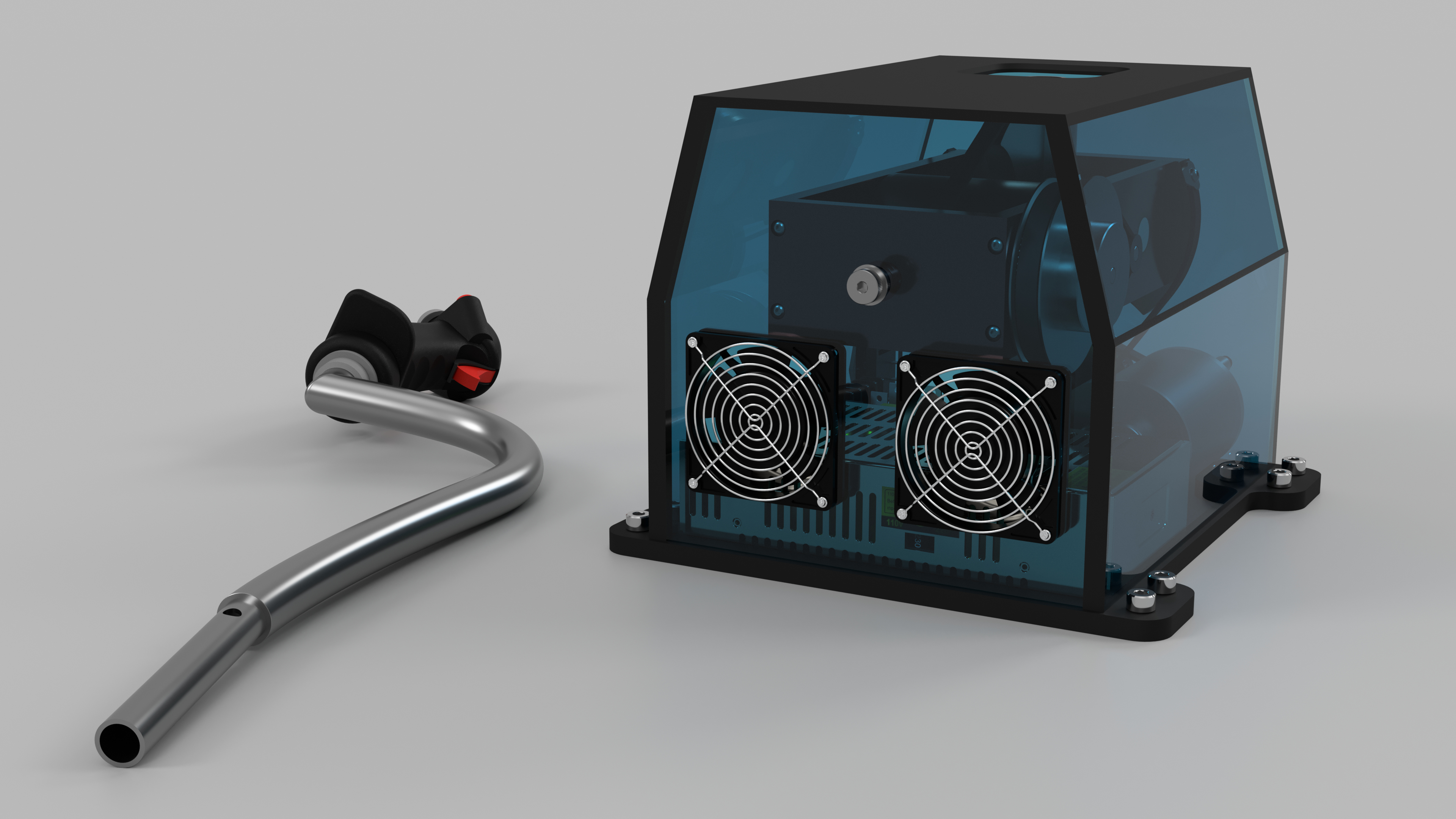
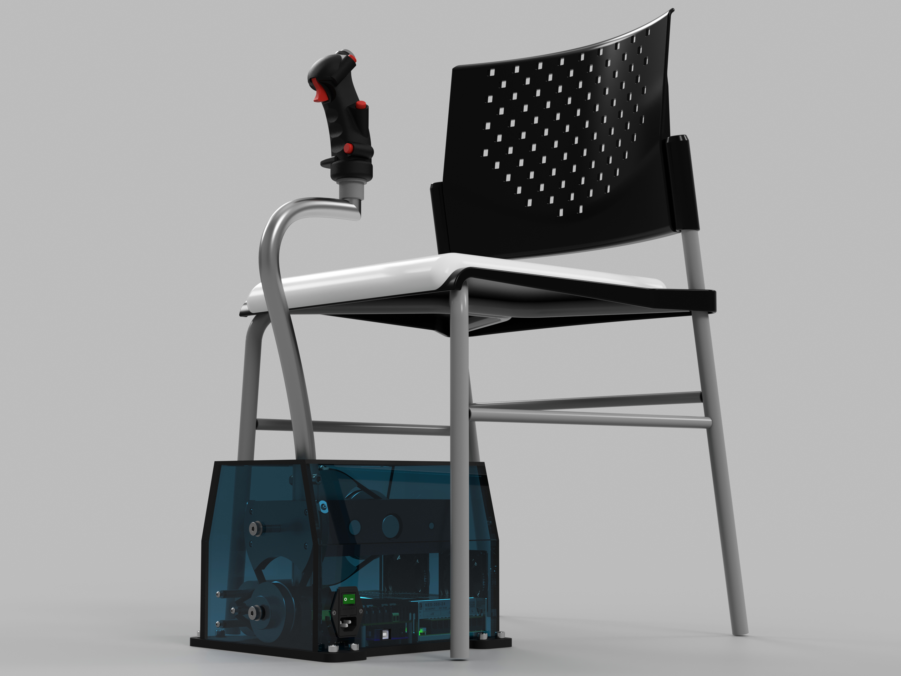
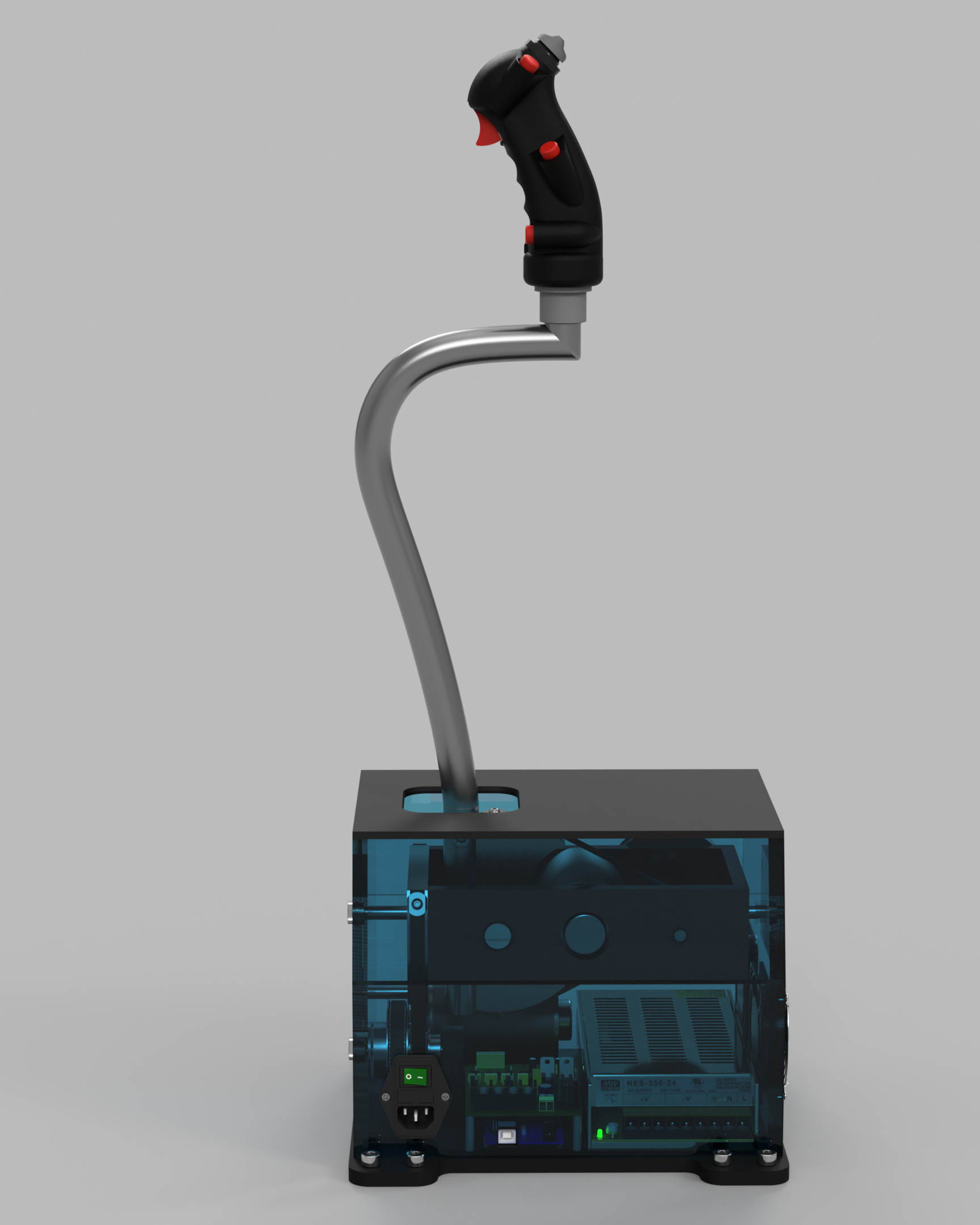
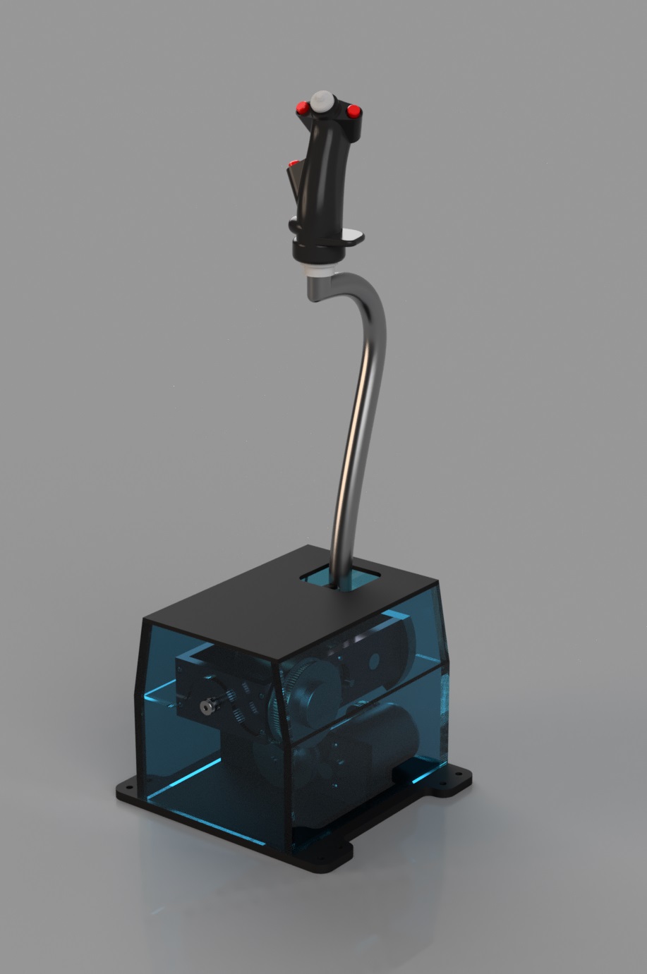
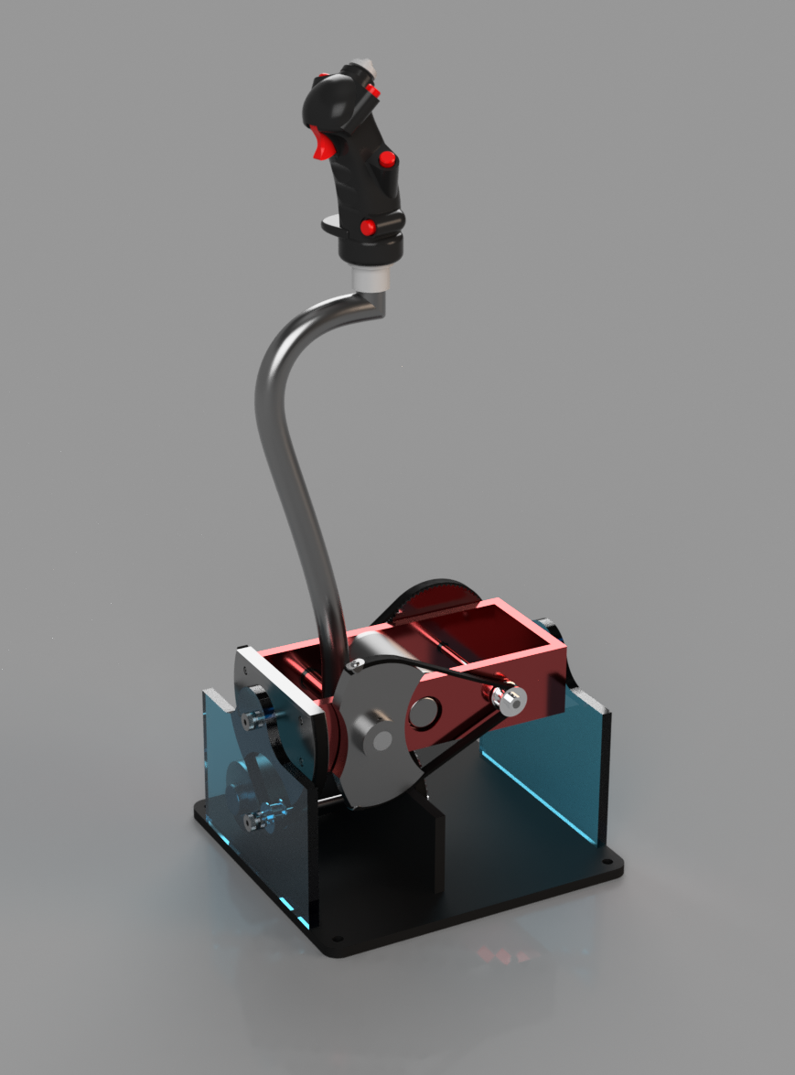
Finally as promised, here are some pics (still rendering more). I call him "BadBoy - Zero" :D Enjoy...
-
Open Source Joystick FFB / DIY FFB Joystick
VR FlightSim replied to Berniyh's topic in PC Hardware and Related Software
Hi Have a look at my web to see what you can achieve with 3D printer.. Basically it is possible to print quite strong components (if well designed) but every surface that is to be precisely fitted to another or is moving against another one, should be really replaced or supported by metal part. That's the conclusion from my endeavor:smilewink: My web - https://vrflightsim.wixsite.com/mysite/in-progress -
Open Source Joystick FFB / DIY FFB Joystick
VR FlightSim replied to Berniyh's topic in PC Hardware and Related Software
I mean thread not threat:) Well two things come to mind reading your post.. First: There is only so much MSFFB2 sticks in the world though, we will have to come up with alternative eventually.. Bigger companies gave up because of the stupid law suits but we are not dependent on them any more (as we were decade or so ago). With so much tech available to buy, resourceful open minded community of enthusiasts and professionals, we can pull this of and develop something even better that MSFBB2. Second: The winding technique has it's limits in number of revolutions on the winding axis thus transmission ratio. I know you'll suggest the transmission ratio should not allow for to much spin on the motor it self because of the inertial feel. However moving the stick in the real plane introduces some inertia as well.. You are moving lot of mass around. -
Open Source Joystick FFB / DIY FFB Joystick
VR FlightSim replied to Berniyh's topic in PC Hardware and Related Software
we can use combustion engine if you want lot of torque, cheap:D -
Open Source Joystick FFB / DIY FFB Joystick
VR FlightSim replied to Berniyh's topic in PC Hardware and Related Software
Well that is a beast in deed.. BUT where you gonna get 80A of current for each one of those? Money vs Torque.. -
Open Source Joystick FFB / DIY FFB Joystick
VR FlightSim replied to Berniyh's topic in PC Hardware and Related Software
As this project is really a community effort, I believe the Interfacing solution is being worked on by others. I have no skills in programming so my contribution is what you see above. We are aware of shaft winding and also "driven pot" solution that you designed (don't take me wrong but one can not miss that in this threat) and as much as I'm sure that it provides the smoothest transmission, I kind of don't like the idea of assembling, tuning and maintaining such device. I still appreciate your input though:thumbup: -
Open Source Joystick FFB / DIY FFB Joystick
VR FlightSim replied to Berniyh's topic in PC Hardware and Related Software
All right boys.. This picture will give you an idea about the final size of my design. All the "power" components are modeled after real goods that are on my "buy to test" list and everything was compacted as much as possible. Still need to finish belts and some bits and bobs but it's looking neat already:D MetalGear Honk, how is the code coming along?:smartass:
-
Open Source Joystick FFB / DIY FFB Joystick
VR FlightSim replied to Berniyh's topic in PC Hardware and Related Software
Hi Miles All that sound very impressive mate. Although I'm not completely convinced that the steppers are the best choice, I would love to see more about your setup, especially the implementation of force sensors. I may be wrong with the choice of brushed DCs however building a test rig is the only way to find out:joystick: The feel of my FFB Yoke powered by DCs is still quite satisfying though. I've got very good feeling about where this is going :thumbup: -
Open Source Joystick FFB / DIY FFB Joystick
VR FlightSim replied to Berniyh's topic in PC Hardware and Related Software
BTW anybody in UK with descent metal workshop? -
Open Source Joystick FFB / DIY FFB Joystick
VR FlightSim replied to Berniyh's topic in PC Hardware and Related Software
Hey all I think that the physical design between mid-range and heavy-duty needs to be significantly different . Each version will have very different motors in size, gearing, PSU, etc. Overall size of the device will change accordingly as we want to have all the components neatly packed to smallest possible space. The brain however (Arduino+control loading software), should be identical for any individual mod. Everybody can choose theirs own H bridge, motors and psu. I have finally chosen my pulleys that I think are gonna work best, DC motors and belts so I will change this in the CAD model and show you the whole thing soon. I'm also ordering these parts now to make simplified version of the transmission first and test the feel of it. Will keep you posted. Jay -
Open Source Joystick FFB / DIY FFB Joystick
VR FlightSim replied to Berniyh's topic in PC Hardware and Related Software
Thanks :) I need to share few numbers with all of you involved. There is one crucial ratio that I was grinding my teeth about last couple of weeks. "Money vs Torque". In my opinion, project like this should not exceed £300 budget. It wouldn't make sense if it was any more expensive because there are already other options available for "higher price" e.g. BFF driver cards for BLDC motors. However building 300 quit FFB device has it's limitations. Considering prices of DC motors, suitable power supply unit and driver cards, I think we are looking at max possible torque of our DC motors about 0.5Nm. With reasonable gear reduction, keeping in mind acceptable inertia of the motors, the system like the one I'm drawing, will be able to generate no more than 4-5Kgf on top of 500mm long stick. To achieve mentioned 10Kgf, we would have to stretch the budget way over £500. As for my self I'm gonna live happily with 5Kgf limit;) Let me know what u think gang... Jay -
Open Source Joystick FFB / DIY FFB Joystick
VR FlightSim replied to Berniyh's topic in PC Hardware and Related Software
Hey boys It's been little quiet around here, I hope everybody's busy working on OSFFB:smilewink: I was quite ill last week so I've done ton of research on DC and BLDC motors, PSU's, drivers, torques, transmission techniques and so on and on... Finally I managed to draft concept design for my "floor mounted" control stick. It's a work in progress however half past one in the morning here so I wanted to post at least one teaser shot before I fall into my bed. More coming soon!:pilotfly: Jay
-
Open Source Joystick FFB / DIY FFB Joystick
VR FlightSim replied to Berniyh's topic in PC Hardware and Related Software
just found very impressive "unclassified" document on this subject from 1948;) http://www.dtic.mil/dtic/tr/fulltext/u2/639028.pdf -
Open Source Joystick FFB / DIY FFB Joystick
VR FlightSim replied to Berniyh's topic in PC Hardware and Related Software
Briliant, thanks VO101_MMaister One more question though. I'm currently drawing the mechanism and it occurred to me that 30 degree motion range (as on the small stick) is probably way too much for 500mm long shaft.. Any suggestions on the travel range on top of the stick? Jay -
Open Source Joystick FFB / DIY FFB Joystick
VR FlightSim replied to Berniyh's topic in PC Hardware and Related Software
10kg at the stick is probably a good target. Not too weak but a challenge at the same time:) Do you guys suggest we have the same max. force (10kgf) on both, pitch and roll? Or is one of them always bigger than the other? Jay -
Open Source Joystick FFB / DIY FFB Joystick
VR FlightSim replied to Berniyh's topic in PC Hardware and Related Software
Hey I can not agree with you. The second stage (belt) will reduce the backlash of the first stage (spur). For example we will have 1 degree rotational backlash on the second gear of the first stage. When we run belt from here (20 teeth pulley) onto second, final pulley (100 teeth), the backlash will reduce 5x resulting in 1/5 of a degree. Just an example though In conclusion, it's better to keep higher transmission ratio on the second stage.. Jay -
Open Source Joystick FFB / DIY FFB Joystick
VR FlightSim replied to Berniyh's topic in PC Hardware and Related Software
yeah, I ting the last one I posted is gonna have rubbish gearbox for our purpose.. So it's either two belts or spur/belt for my setup. I'll sketch something tonight. Jay -
Open Source Joystick FFB / DIY FFB Joystick
VR FlightSim replied to Berniyh's topic in PC Hardware and Related Software
Guys THIS is quite exciting! https://forandor.com/index.php?route=product/product&path=68&product_id=367 First two spur gears already in place (NO worm). I'm just slightly worried about the play in the gearbox. Anybody has any experience with these units? -
Open Source Joystick FFB / DIY FFB Joystick
VR FlightSim replied to Berniyh's topic in PC Hardware and Related Software
or this one.. http://www.ebay.co.uk/itm/24-VOLT-120-WATT-ELECTRIC-BIKE-BICYCLE-E-SCOOTER-MOTOR-24v-120w-/172913375055?_trksid=p2349526.m2548.l4275 Not sure about the torque here.. -
Open Source Joystick FFB / DIY FFB Joystick
VR FlightSim replied to Berniyh's topic in PC Hardware and Related Software
how about this one? https://www.ebay.co.uk/i/360393713040?chn=ps&dispItem=1&adgroupid=13585920426&rlsatarget=aud-133395220626%3Apla-142413584466&abcId=&adtype=pla&merchantid=109953874&poi=&googleloc=1006886&device=c&campaignid=207297426&crdt=0 I found it's specs elsewhere. The torque is 0.9Nm while current about 13Amps That should do the job:) -
Open Source Joystick FFB / DIY FFB Joystick
VR FlightSim replied to Berniyh's topic in PC Hardware and Related Software
Hey guys @Slartibartfast Thanks for the tip on the youtube videos. I couln'd figure it out and it was late night so I gave up and only posted the link. Fixed now;) About "floor mounted" design. While the "cross" solution as seen in my video is working great in the simulation, it is also very technically demanding in the manufacturing process. Every single component needs to be "spot on" as there is 9 different joins working in conjunction with each other. To be honest, I would not attempt to recreate this mechanism without proper CNC equipment. As I mentioned earlier this is great design for small spaces where minimum size boxing is required however building floor mounted stick give you a lot more options and space to utilize. Therefore we can design (I will try next) much simpler FFB mechanism that can be build in everybody's workshop.. Bigger but Simpler:joystick: BTW - did you get my reply on the programming subject? @everybody Forget about the magnets guys. It's not "home build" solution and it is not at all cheap as well. Brushed or brushless DC motors are the way to go. Cheap, strong, easily accessible. I've build plenty of test setups over the last two years. In order to get great force/torque on the stick, I would suggest two stages of transmission. 1st. Two cog gears (motor shaft + one) 2nd. Two belt pulleys (small one fixed to the +one) This will provide great transmission ratio/force with minimum play on the stick. Also allowing for use of cheaper motors.. Jay