acidwise
-
Posts
22 -
Joined
-
Last visited
1 Follower
-
Post MotherBoard Specs Of Bricked TM Warthogs Here Please
acidwise replied to twobells's topic in Thrustmaster
Check the older message for repair instructions: The ESD6 and similar diodes in SOD-123FL package can be mounted with a soldering iron without preheating the board. To mount the other one (uDFN-6), a hot air soldering station is necessary. The diodes I used are designed for ESD protection of USB 2.0 interfaces. One could also try to use other "basic" TVS diodes with low capacitance (about 1 pF or less) for the data lines as well, adding them to the respective R11 and R12 pads. I just wanted a more elegant solution and had no problems with soldering equipment. -
Post MotherBoard Specs Of Bricked TM Warthogs Here Please
acidwise replied to twobells's topic in Thrustmaster
According to the datasheet, this is primarily an EMC filter with ESD protection at the data lines. EMC is not an issue for a joystick, but ESD protection would definitely be good for Warthog. Unfortunately it is a bit overpriced and out of stock. ESD6 is an ESD protection on the USB power line of the chip (U1). I am not sure what the others do (too lazy to open the throttle and trace it), but it is definitely not at the USB data lines, which is the largest concern after the firmware suicide so far. -
Post MotherBoard Specs Of Bricked TM Warthogs Here Please
acidwise replied to twobells's topic in Thrustmaster
There is a problem with serial communication between psocdude and hssp. There are only a few possibilities: wrong device used - double-check which device appears and disappears when you plug your arduino hssp in and out device inaccessible to user - try running psocdude with sudo (or under root) or set proper rights for the device wrong port settings - the hssp programmer is set to 115200, other settings (parity etc.) may apply damaged arduino wrong sketch I would try to check the arduino first (e.g. load Blink sketch). You can check the serial communication (both in Windows and Linux) with a loopback test. A software loopback would actually check both points at once: void setup() { Serial.begin(115200); } void loop() { if (Serial.available()) { Serial.write(Serial.read()); } } -
Post MotherBoard Specs Of Bricked TM Warthogs Here Please
acidwise replied to twobells's topic in Thrustmaster
Unfortunately Thrustmaster saved a lot on wrong things in this controller set, primarily the joystick gimbal. Are you sure the Arduino is recognized as /dev/ttyACM0 or have you used the proper device? I guess I forgot one important step: after downloading psocdude, it should be compiled. The psocdude/BUILD script downloads the wrong version of psocdude first, so comment the respective line or do a manual build: ./bootstrap ./configure make There are some dependencies, which should be installed first. Check psocdude/README. -
Post MotherBoard Specs Of Bricked TM Warthogs Here Please
acidwise replied to twobells's topic in Thrustmaster
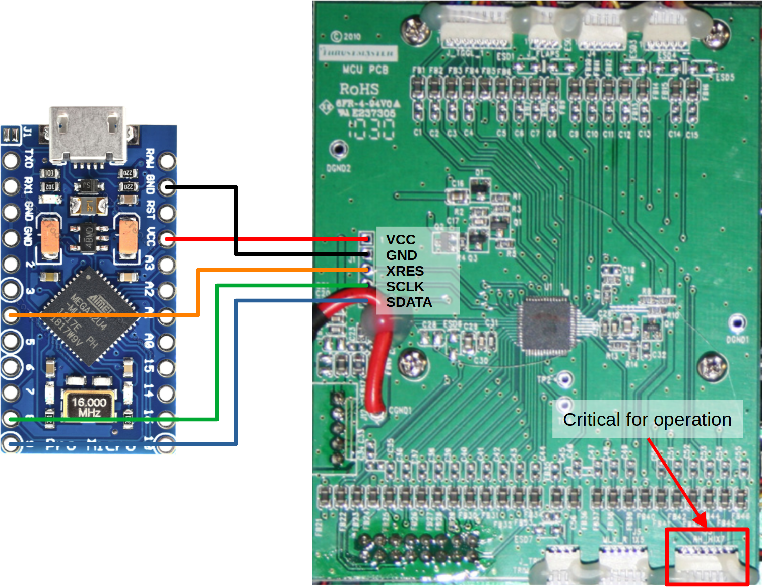
Allright, there should be instructions for an average user anyway, just hard to find time for it. I would suggest to remove the board completely for soldering and programming, but this is not really necessary. You can just solder the wires to the PCB as it is. The pinout is defined in arduino_hssp/issp_defs.h With default settings, the connection should look like this: The pinout for other arduinos will be basically same, unless you edit issp_defs.h. Using RAW instead of VCC pin for a USB-powered (not with 12V or so external supply attached) Arduino is OK. All you need regarding the Arduino software is discussed in one of the previous posts. To flash the chip, you will need: Prepare the Arduino HSSP programmer: program your Arduino with the arduino_hssp sketch via Arduino IDE. This can be done under Windows. Prepare a Linux machine (e.g. VM) and copy psocdude and the firmware to it. I used a folder /etc/psocdude, but had to claim owner rights and allow executing scripts in it: sudo chown -R ubuntu:ubuntu /etc/psocdude sudo setfacl -R -m u:ubuntu:rwx /etc/psocdude Compile psocdude: cd /etc/psocdude ./bootstrap ./configure make Connect your Arduino to the Warthog PCB, then to your computer and then tunnel the USB device to your virtual machine. In the VM, open Terminal, go to your psocdude folder and make a backup first: sudo psocdude -C psocdude.conf -p CY8C24894 -c arduino -P /dev/ttyACM0 -b 115200 -U flash:r:backup.bin:r Optional: use a hex editor to replace the last 64 bytes in TM_Warthog_Throttle_v23.bin with the respective part of your backup.bin, since it seems to contain calibration data, as discussed here and here. Flash the chip: sudo psocdude -C psocdude.conf -p CY8C24894 -c arduino -P /dev/ttyACM0 -b 115200 -U flash:w:TM_Warthog_Throttle_v23.bin:r Disconnect the Arduino from PC and PCB, connect at least the RH_H1X7 and plug in the throttle for a test. If the throttle is recognized, congratulations! Proceed with calibrating it by using the TM software. This is how successful programming looks like: Usually the Arduino HSSP is connected as /dev/ttyACM0 (USB ACM device). You can check it by using: dmesg | egrep --color 'serial|tty' And here is my PCB with a swapped chip, added HSSP header and ESD protection for VCC and USB (marked):
-
Post MotherBoard Specs Of Bricked TM Warthogs Here Please
acidwise replied to twobells's topic in Thrustmaster
I would say, flashing is worth a try. If it does not work out, there is always an option to replace the chip. -
Post MotherBoard Specs Of Bricked TM Warthogs Here Please
acidwise replied to twobells's topic in Thrustmaster
Pity the bootloader method did not help. Does your PC recognize the device at all? It is actually normal, that microcontrollers need a programmer. USB flashing with Arduino is a luxury, which is available to us due to a preinstalled bootloader and/or additional chips on the board. -
Post MotherBoard Specs Of Bricked TM Warthogs Here Please
acidwise replied to twobells's topic in Thrustmaster
Glad if that can help! 1. It is possible to reflash a chip even with a damaged USB part. However, in this case the joystick will not be recognized and a replacement will be necessary. I have some chips at hand now. 2. If there appears a plug-and-play connection sound when you plug your device in, the USB connection is fine. It seems the firmware is damaged and the chip only needs to be reflashed. I would suggest the bootloader method first. 3. It should be possible with most of the Arduino boards, just make sure to select proper pins or adjust the pin definitions in arduino_hssp/issp_defs.h accordingly. @walmis has a version optimized for STM32F103 "Blue pill", which in its turn has clones selling for 2$. Be prepared for some hassle with Linux though, there were some issues installing the dependencies, but in the end it worked out for me. Unfortunately I did not document it well enough to share. Feel free to ask questions / show your way - it will be helpful for others. HWarthog_Bootloader_Method.pdf -
Any progress? I have a terrible in AFR mode or only one card working in SFR mode. The problem seem to be primarily with lighting and clouds.
-
Post MotherBoard Specs Of Bricked TM Warthogs Here Please
acidwise replied to twobells's topic in Thrustmaster
The only one seller actually shipping my order (CY8C24894-24LTXI): https://www.aliexpress.com/item/32838273747.html -
Post MotherBoard Specs Of Bricked TM Warthogs Here Please
acidwise replied to twobells's topic in Thrustmaster
Ladies and gentlemen, I am proud to announce a great success in repairing the Thrustmaster HOTAS Warthog throttle! Member #28658 is back in the ranks! After successful experiments with a new PSoC1 chip (thank you, @walmis ), I finally determined the reason for my PCB "not working" with the reconstructed firmware. There was some misconfiguration in the arduino_hssp, which might play a role, as well as some hardware-specific feature, which I will discuss later. My throttle is now recognized by the system and fully functional. In my case, the USB port seems to be damaged and required a replacement of the chip (CY8C24894-24LTXI). This is a QFN chip with a large GND pad, so it requires some hardware and skills to replace it. To provide an ESD protection, I have installed TVS diodes for USB data and power line. This is not mandatory, but hopefully prevents the device from getting damaged in the future. In case of a firmware corruption, a bootloader method can be used to flash the device. If the bootloader is corrupted, this method may not be available. Provided the chip is electrically intact, the function of the throttle can be restored by reflashing it with an Arduino. This process will require some very basic soldering skills and is accessible to virtually everyone. To reflash the Warthog throttle, some hardware and software is necessary. Hardware: Soldering iron, solder, at best also some flux. Any, even the cheapest device and set from you local hardware store will do the job. Arduino Leonardo or Pro Micro Dupont cable, 5 pins, female to female (Pro Micro with male headers) or female to male (Leonardo with female headers), to connect your Arduino to the throttle PCB 5-pin header (at best - right-angled) for the throttle PCB Optional: ESD protection. SP3400-02UTG (1x) and SMF4L5.0A-Q (1x) TVS diodes. The selection is dictated by the board tracing (D+/D- trace spacing and ESD6 pads). Placing the diodes on the PCB as well as replacing the CY8C24894-24LTXI chip will require high soldering skills and a hot air soldering station. In addition, replacing the PSoC without a board preheater cannot be recommended, since the entire lower side of the PCB is drawing heat away from the chip via its GND pad. Software: Arduino IDE arduino_hssp (see attachment or Github). This is a firmware for the Arduino PSoC1 programmer. My version is a mixture of three versions by miracoli, trou and walmis, which is configured for Arduino Leonardo and the respective target chip. For windows users: VMWare Workstation Player For windows users: Some Linux image (Tested with Ubuntu 20.04.3) psocdude by walmis (it contains proper flash data for the target chip). There are some instructions provided in the readme of the respective packages. This is already a long post, I will update it with more details on the programming later on. If the PCB was removed from the throttle for repair, do not urge to connect it to your machine after flashing the firmware. The throttle will not start and there will be no USB connection at all, if the RH_H1X7 connector is not plugged into the board. In the same way, damaging the respective cable or breaking the right-side throttle off will render the throttle irresponsive. Restoring the connection should solve the problem. This is the hardware-specific feature I mentioned in the beginning, which rendered the chip "dead" and costed me 1 more evening experimenting with the chip and verifying its health status. If the repair is successful and the necessary connections are done, there appear "HID-compliant game controller" and "USB Input Device" with VID 044F, DEV 0404, REV 0100 in the "Human Interface Devices" section of the Device Manager, as well as the "Throttle - HOTAS Warthog" in the "Game Controllers" panel. Hopefully, these instructions will help someone to bring a beloved throttle back to life. I also hope, that Thrustmaster will not strike down upon thee with great vengeance and furious anger those who would attempt to repair their own throttles and therefore poison and destroy the additional revenue of the company, but improve their products in the future. I would like to thank @Janssen and especially @walmis for their contribution. Unfortunately, the chip is currently out of stock at major electronics distributors, but is available for back order. If there is an interest, we can try to order some and provide a hardware repair possibility in Europe. arduino_hssp-master_acidwise_v3.zip TM_Warthog_Throttle_v23.bin psocdude-master_walmis.zip -
Post MotherBoard Specs Of Bricked TM Warthogs Here Please
acidwise replied to twobells's topic in Thrustmaster
Update. Received a chip from @walmis. Added TVS diodes for ESD protection on the USB and power line. Swapped the chip and flashed. ubuntu@ubuntu2004:/etc/psocdude$ sudo psocdude -C psocdude.conf -p CY8C24894 -c arduino -P /dev/ttyACM0 -b 115200 -U flash:w:TM_Warthog_Throttle_v23.bin:r psocdude: AVR device initialized and ready to accept instructions Reading | ################################################## | 100% 0.01s psocdude: Device signature = 0x001f psocdude: NOTE: "flash" memory has been specified, an erase cycle will be performed To disable this feature, specify the -D option. psocdude: erasing chip psocdude: reading input file "TM_Warthog_Throttle_v23.bin" psocdude: writing flash (16384 bytes): Writing | ################################################## | 100% 20.27s psocdude: 16384 bytes of flash written psocdude: verifying flash memory against TM_Warthog_Throttle_v23.bin: psocdude: load data flash data from input file TM_Warthog_Throttle_v23.bin: psocdude: input file TM_Warthog_Throttle_v23.bin contains 16384 bytes psocdude: reading on-chip flash data: Reading | ################################################## | 100% 8.29s psocdude: verifying ... psocdude: 16384 bytes of flash verified psocdude done. Thank you. Unfortunately, the chip behaves similar to the previous one - no voltage at the USB data pins. In addition, the flash memory can be easily read. I guess, I am missing something. Looks like there should be some fuse bits programmed (not sure if PSoC1 have them at all) - has anyone an idea? Upd. From all sources I could find, in order to program a PSoC1, a hex file is necessary. There are some example projects available from the Infineon website. I checked some of these (e.g. CY8CKIT_015_Example_Project) and found, that the file in addition to EEPROM contains some configuration sections. Presumably there are memory protection and other metadata. The later may contain CPU configuration. Some reading which seems to be relevant could be find in the links to the following thread: https://community.infineon.com/t5/USB-EZ-PD-Type-C/About-writing-HEX-file-to-the-internal-Flash-of-CY7C65219-40LQXI/td-p/217698 . Now there are 2 problems: 1) Read or generate proper configuration 2) Write the configuration to the chip. Upd2. PSoC1 ISSP Programming Specifications explain the format and content of the hex file. It basically contains the ROM and memory protection sections. No other information is necessary to program the device. Created a LED Blink project with PSoC Designer, flashed the .hex file with psocdude. The project works as intended. Psocdude can write and read intel .hex files just fine. The security configuration functions are not implemented in arduino_hssp and possibly psocdude, therefore the ROM remains readable. Hence no need to convert a .rom file into .hex - the .rom firmware is fully operational, but the additional features of .hex are basically not implemented in my hardware. Upd3. Implemented USB-UART bridge to see whether the USB lines are OK. They are. The device is recognized by the OS and is functional. -
Post MotherBoard Specs Of Bricked TM Warthogs Here Please
acidwise replied to twobells's topic in Thrustmaster
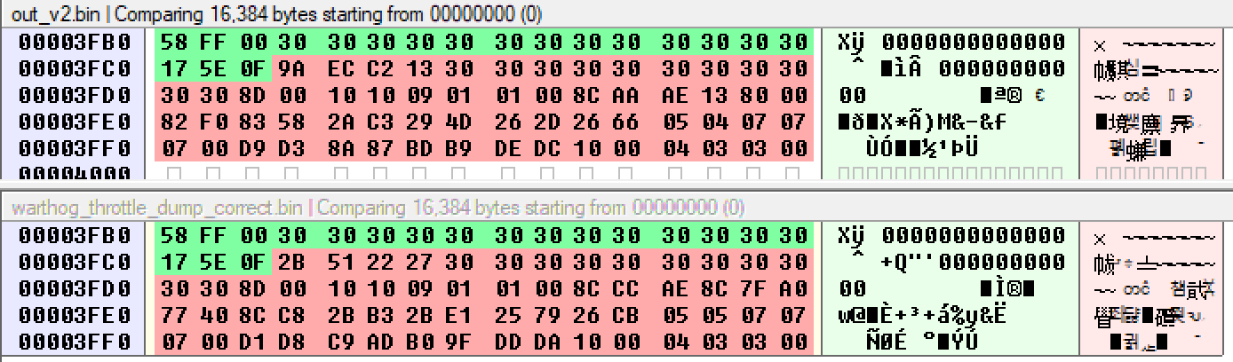
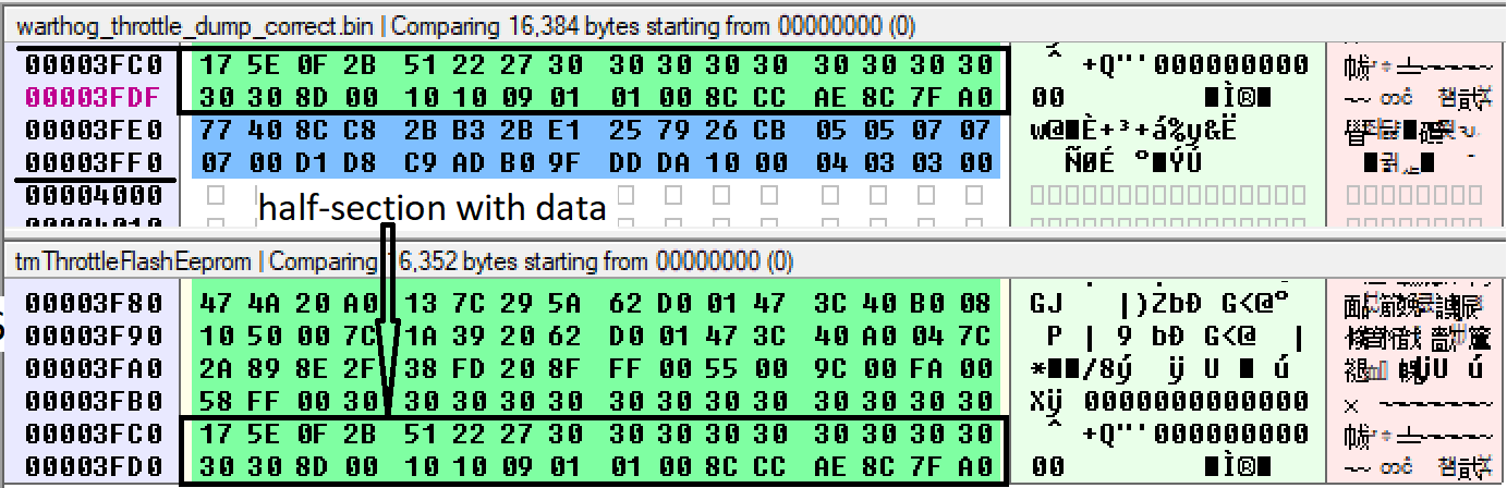
Nice! Thank you very much! Total euphoria! Thank you very much for trying FSR, was about to order a new board for tests. Unfortunately my chip seems to be damaged at the USB side. Nevertheless, to finish the topic, I have a couple of questions regarding your hssp routines and flashing without erase (which shouldn't actually happen). Expect a follow-up. Props for sharing! upd1: Identical 180-byte section in bootloader (1E69h and E32h). Does not necessarily an error, but interesting. Calibration is not a big loss anyway, since there is a tool available: TM Joystick Calibration tool 1.13.rar FSR seems to omit the last 32 bytes (half a section). Weird. Flashing via HSSP will require full 16K dump. What bothers me somewhat is 7Dh (LJMP) at 0 offset. @Janssen had 51h (MOV A). psocdude: verification error, first mismatch at byte 0x0000 0x51 != 0x00 It is also interesting, that this section was not wiped after flashing the dump with an empty bootloader. There should have been a locked interrupt table. Did not expect it much to change. Both opcodes seem to make sense though. upd2: Meld arduino_hssp from trou und walmis to work with Leonardo. Now the dump looks much better. The bank selection, as I assumed, was the reason. The patch by walmis (see arduino_hssp.ino) solves the issue. I don't see a point in forking once again, @walmiscould you maybe submit a pull request? The correct dump is here: out_v2.bin The version can be read at 1700h (00 17 00 01 -> v.23). It seems the entire last block contains calibration data. Is dumping a half of the section a bug or a feature of FSR - who knows. Really important is that it dumps the protected part of the flash. I would expect, that flashing the FSR dump will restore the device functionality, but misalign the axes, unless the remaining 32 bytes are extracted via hssp beforehand and added to the dump. A recalibration will probably be necessary, if the section remains missing (agreed with @walmis). The ready-to-flash firmware is here: TM_Warthog_Throttle_v23.binNot tested yet, waiting for blanks.
-
Post MotherBoard Specs Of Bricked TM Warthogs Here Please
acidwise replied to twobells's topic in Thrustmaster
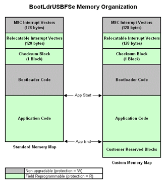
@walmis could you please try the FSR tool? In case it bricks your board I will buy it for the price of the replacement part, so it is fair. Anyhow, thank you for sharing. I am new to the PSoC and the links you provided are valuable. Will see how far can I get. I guess you have much more experience in that topic and I would appreciate any advice. However, at this point I am skeptical about the romx approach, looking back at the Aigo hack. 1. By just looking at the dump I have noticed, that the sections 14C0h - 1FFFh and 34C0h - 3FFFh are identical. That seems weird: I see no reason to duplicate the code in the flash. There might be a problem with the data read (i.e. wrong bank). 2. According to AN2100, the bootloader should be in 3600h - 3FFFh. Why would it land into 0h - 14BFh? Maybe we do already have it from tmf? Or is the address space reversed somehow? 3. If block checksum verification are used, which should be the case (found some comments mentioning automatic entering the bootloader mode with a corrupted flash), there must be a checksum section. Again according to AN2100, in 3500h-3600h. In addition, the bootloader checksum section should be also in the application space: 35D8h - 35FFh, I guess. This provides some good starting information. 4. The 64-byte blocks in 2000h-34BEh are identical, which is again strange at the first glance. Hopefully the disassembler will provide a better insight... Should we spin off the hack thread? upd1: 5. A few posts ago you have shared the security configuration. There are only 128 blocks out of 256 listed. Is it a cut citation or an incomplete read? upd2: Set up Win7 VM with PSoC Designer. Checked the datasheet of the BootLdrUSBFSe_5 module. It is somewhat different to AN2700. It looks like there is no checksum block in the application area, which is pity. The bootloader should actually be protected and expected to be in the first part of the address space together with the read-only interrupt vectors part, which is always write-protected. It seems that the address space in AN2700 is "inverted" and the bootloader is missing in the dump. Analyzed v23.tmf a bit further. Will update if something more becomes obvious. 0x0: header "FWFG" 0x04: 80h - application code offset? 0x68: 17h - version (23) 0x6C: firmware date 0x70: firmware compilation time 0x6BA: 4F 04 04 04 00 01 - USB IDs (VID 044F, DEV 0404, REV 0100) 0x538: USB device name string Unfortunately, VID 044F, DEV 0403 for "bulk" throttle (bootloader mode) is not in the file. Hence, the bootloader is not provided with the .tmf as well (unless encrypted / compressed).
-
Post MotherBoard Specs Of Bricked TM Warthogs Here Please
acidwise replied to twobells's topic in Thrustmaster
Bought #28658 broken with the same problem: device not recognized. Initially had 3.2V at D+, 0V at D-. Measured the resistance and voltage drop (diode test mode) at D+ and D-: about 20 MOhm, 0.76V. Observed no activity with the oscilloscope. After the measurements got 0V at D+ too and no recognition from the system whatsoever, respectively. I guess, this CY8C24894-24LTXI is really succeptible to ESD... This is the first IC I managed to further damage this way. Reworking the chip did not help (as actually expected), so walmis was lucky. By the way, don't even bother to replace it without a preheater (board temperature about 140° C). Let's see if I get something out of HSSP. Waiting for ICs from China. @Janssen: do you have the replacement chips on hand? Could you please try to measure the resistance and voltage drop (with reversed probe polarity) of the D+/D- lines of your chip and the replacement one? The latter may go bad after the measurement... upd1: If somebody in Europe can donate a broken PCB, please let me know. In case of success the firmware will be available publicly. upd2: Managed to dump the firmware (see attachment). There are some difference with the file from walmis. For example, everything up to 0h14BF is completely empty. Need to think about it. out.bin upd3: Trying to understand the original firmware. Found v20 version from 2011 (see attachment). Looking for 2010_TWHM_1.exe driver pack, which should include HA10T_PSOC_USB_v18.tmf HA10T_PSOC_USB_v20.tmf upd4: Working on a vector attack. Current problem: arduino_hssp from trou does not work, but seems to be necessary. There is quite a number of differences to the version by miracoli, trying to locate the issue. @walmis, how far have you got with the vector attack using the blue pill? Can someone with a working board dump and share the firmware by using the Thrustmaster utility FlashSpaceReader? This may be a faster way. A copy is attached, original at ftp://ftp.thrustmaster.com/accessories/pc/hotas/exe/HOTAS_Warthog/TMHW_FSR.zip TMHW_FSR.zip