lesthegrngo
-
Posts
1245 -
Joined
-
Last visited
Content Type
Profiles
Forums
Events
Everything posted by lesthegrngo
-
I didn't figure out what was going on, but the game control settings do now recognise the extra buttons. I don't know if it was something to do with me trying to get Helios working or messing with the export.lua files but right new it works. Sorry I can't be more helpful! Les
-
Helios error and monitors help requested ***SOLVED*****
lesthegrngo replied to lesthegrngo's topic in Home Cockpits
I found the answer to this - what you do is go to the users / saved games / DCS / scripts folder and find the export.lua file. Rename that exportbak.lua. Now if you go to Helios you will be able to get Helios to work, it will create a new export.lua however it will now not have the code in it that will allow DCS Bios to work. To fix this open the new export.lua file created by Helios with Notepad++ and append the following line just below the line that contains the reference to Helios dofile(lfs.writedir()..[[Scripts\DCS-BIOS\BIOS.lua]]) Save the file and you should now have both Helios and DCS Bios working Cheers Les -
Hi all, I have had this issue before and it seems to have come back again. It used to be that using L-alt+f1 I could select the HUD only view. That now does not work, even though I checked it in the Controls settings. It is still reporting it as L-alt+f1, however I also assigned the command to a Bodnar board driven key navigation panel. The binding is accepted by the controls interface, it lets me save it and it is persistent (I can exit the game and go back in and it is still there), however neither the L-alt+f1 nor the assigned button allows the HUD view Is there a secondary setting that disables this that I am unaware of? This is the case for both the A10C and the A10C-ii cheers Les
-
There is another possibility - if I try loading a sketch to an AT168P Nano using the 328 bootloader or the 328 (old bootloader) in the 'tools' - 'processor' list, if I leave it long enough it will give that error. If the bootloader selected doesn't match it can't communicate with the nano Cheers Les
-
Yes, in the IDE itself, I’m not in front of the Pc so can’t check, but if you go the drop down menus you will see it. it is easy once you get used to dealing with it, you will probably have to do it many times with all the DCS bios stuff! cheers Les
-
Go to the IDE library manager and search for ‘joystick’ and you will see an option to download and install it cheers Led
-
Not sure if this has been linked before, but this may help someone Cheers Les
-
I wonder if your monitor setup.lua file is corrupt
-
In DCS setup check which monitor you have as the one set to display - it might have inadvertently been set to one of the standard ones that come with the MFCD's Les
-
Glad it was of use! If you go to the Capt Zeen site, you will see a little Discord Icon, if you click on it it will take you there plus give you an automated invite that is valid for a certain period You say double exported MFCD's, have you got one in the viewport method and one in Helios? Cheers
-
Hi all I posted a reply to one of my own threads on the home cockpits forum regarding how to use an existing Capt Zeen Helios profile that works with DCS to produce your own one with just the stuff you need on it. It has dawned on me that being tucked away in that thread is not going to help many people simply because it is not an obvious place to be. As a result this is a copy of what is in there as I belongs in this thread. Essentially a working profile is used as a basis to create your own. For those who wish to know how I did it, it was surprisingly easy, if a little bit laborious. A big shout out to MadKreator37 over on the Helios Discord channel, without whose help I would still be struggling To summarise, the process is as follows. Firstly, go to your User/saved games/scripts folder and back up your copy of the Export.lua file (call it Exportbak.lua or something like that) Go to the Capt Zeen website and get one of Capt Zeen's predone profiles, in my case the A10C version, open it in the Helios editor and do the 'reset monitors' thing, setting everything on the main monitor. In my case, opening up the profile showed two monitors, 1 (main monitor) and a second one with a load of stuff on it. Resetting the monitors allows you to tell Helios to move the contents of monitor X to monitor Y. Your monitor setup will be different to mine, but you will almost certainly have a monitor that you view the main game on; make Helios move everything to that one. Do not open two instances of Helios editor as you need to work with everything in one instance of Helios Please note that when you do this initial work on a main panel called 'Interface status; you may see a load of errors generated. This is normal, and by expanding each section, if there are issues clicking on the little cogwheel setting icon will generally shop you what needs to be done automatically and by accepting it it will fix it for you, although there are some that are a bit more manual (for example where it says you must save the profile before it can be used) Once you have everything on that monitor, you need to decide what you want and on what monitor to set it on. In my case it was the RWR bezel, the entire HSI, the entire ASI and the entire ADI including the slip ball indicator. The problem is that if you try and look for these they may actually be on sub panels on the main display. On the right hand side you will see a list of all the components being shown in the Layers tab - except it isn't a full list. So, be careful not to delete stuff without knowing what it is. The other thing that may occur is that the images all come up as red boxes with black crosses through them. That is because the images being used by the profile are in a sub folder you downloaded with the profile in it. To correct this you need to copy the image files and subfolders from the download location into the Helios installation images folder. When you save the copy of the profile you are making it should automatically show the correct images. Now you have to start deleting things. If you click on the item in the right hand Layers list it will highlight it on the monitor screen (if you double click on the monitor in the top left preview screen it will open in the main panel - be sure to click on the actual number in the middle of the preview as if you don't sometimes it won't open the screen). When you can see that the highlighted item is something you don't need / want, you can delete it. Continue that process to declutter as much as possible. Eventually you will get to a point where you have a lot less that includes the ones you want, and they may actually be in a sub layer (for instance mine were in a sub-layer called 'main panel'. On the main screen you can double click on these and they will appear in a new screen and all the sub parts will be listed in the Layers tab to the right. Depending on the instrument, clicking on it will open yet another with the sub components of that instrument. Unfortunately that doesn't seem to be very consistent, but it doesn't seem to matter. So assuming you now have a condensed list with just the items you want (possibly with some unwanted extras) now it is time to put the desired instruments in their correct location. To do this you will copy and paste, using either ctrl-c and ctrl-v or the edit-copy and edit-paste commands. Select say the HSI from the layer list; you will see it highlighted on the main screen. Copy it, then open up the screen you want to put it on, and paste it. Doing this has now copied all the subcomponents and layers, and more importantly all the bindings that let it interact with the DCS info. Follow the same procedure for all the desired items, placing a copy of each on the appropriate monitor. Obviously save as you go in case of mistakes or issues. When saving, you may get some other errors generated in the 'interface status' tab, just repeat the actions you did earlier and it should all come good. Some errors might remain but are ones that don't affect the workings. Now you should start the profile using the Helios Control app, and hopefully it will start without errors. If there are any problems it generally will be easy to address, as there is information given. Hopefully it will start OK and so what you will see are two sets of instruments, the original ones on the main screen, and the new ones on the screens you chose. Start DCS and if all went well, your instruments should all show the game generated data, and work with it. If that is the case, congrats, you can move on the next stage. If not you will need to verify the Interface status, and that the Saved Games Export.lua is referencing Helios, which should have automatically happened when you went through the initial Interface Setup error correction Now you have to go through the laborious reiterative process of stopping the profile, dragging the individual instruments to the correct size and positions, then restarting the profile to check it. Bear in mind that while the instruments will snap to the borders, this can easily be overridden by simply typing in the desired position in the top right panel. A lot of mine are set at like -5 from the top so the top of the instrument is off the top of the monitor, so that it displays in the exact location to match my laser cut bezel. The same goes for the left position, height and width. You will have to keep starting the profile, checking it for position and aspect ratio and then correcting as necessary. Once all the positions are correct restart DCS to check that it all works, save it one more time and then save as another filename so that the working one is still there in case you have issues. Once you have done that, go back to the original instruments that are in the wrong place and delete them, leaving only the instruments that you want, and save. If all went well, you new should have a fully working Helios profile. One other thing that I had to do once I was finished with Helios was to ensure that any viewports I had created were correctly aligned with the Helios instruments. For example, the RWR symbols were way off center, being too far to the left and down. In the Monitor Setup.lua file I then had to adjust the start position (x, y) and once I had that correct I had to make sure that the height and width of the viewport matched the Helios version. Again, this is a reiterative process, where you have to change the numbers, see how it looks, and then change it again until you are happy. I would say it took me most of an afternoon to get it all right, but the finished setup looks really great. The thing is that with patience you can do it One last point - you may have to copy the DCS Bios line (something like dofile blah blah DCS Bios) from the Export.lua you backed up at the beginning in order to get DCS Bios working with it. I hope that this helps, I am not an expert on Helios but this worked reasonably easily for me Cheers Les
-
You will see in other threads that my rig is basically 99% finished, but it is the final 1% that will make the difference between a cool DIY project and a really useable flight simulator rig. That 1% can often be a lot of work, or difficult, or both, but it needs to be done. So, as I see it these are the issues that need to be resolved for this to be right. Apart from the first item, they are in no particular order of importance, but are all issues that detract from the experience. Firstly and most importantly, the Altimeter. The one I made works OK in USB mode but doesn't want to know in RS485 mode. I need to redo this it is a critical instrument. I do have the digital OLED version that works perfectly so the fact that the physical needle isn't working is not a show stopper, but I want that to work. If anyone has a solution that preferably works with RS485 I am interested to know about it, My current version used an X27 stepper with the rotation limiter removed, an IR sensor and amplifier circuit and a slit cut into the gauge face matching a reflective needle for 0 homing. I'm not married to it, and am open to alternative ways, although clearly not having to procure any other hardware would be preferable RS485 glitching - I have noticed that when I connect more slave devices to an RS485 slave line, it becomes more prone to glitching, The way it manifests itself depends on the device. With stepper driven gauges they flick full scale as if the Nanos are being momentarily depowered. With OLED devices they will stop displaying the data, or corrupt the data being shown, then come back to the correct date. The CLP will show random lights Devices with warning lights will have the warning light illuminate randomly Switch panels sometimes don't register the switch movement All these devices work perfectly in RS485 on their own, and very often with other devices connected to the same line. However add one more and the glitching starts. I have to assume my circuit design is at least part of the issue, there's probably some filter capacitors or suchlike that I should have included but didn't. For info I run one Mega with three slave lines Switch polling on connection - I did try this, but fell flat on my face. While not devastating it isn't perfect to have the sim start and you can see the physical mismatch between the on screen state and the rig switches. Some will never be able to be set (undercarriage lever anyone?) so there is a limit but I would like to be able to synchronise everything that can be Batch Com port initialisation - I have the Mega, and four ESP32 devices that all need com ports starting before game start. I would be good to automate that OLED device display issues - this is different to the glitching quoted above. This is where my sketches are probably not optimally coded due to differences in the way libraries work or some compromise in the design (like having to rotate the orientation of OLED displays). As a result I get artefacts on the screens, like instead of a decimal point a partial number, or in another instance where the number that appears is not centered correctly Switch cross read - not a huge issue but a bit irritating, this is where you operate one switch and two switches move at the same time, one that is correct and another on the same panel that isn't. A good example is the YAW SYS switches, where the L YAW SYS switch will toggle both the L and R switches. I suspect this is something corrupted in the Arduino libraries when I compile BCD switches refusing to work with RS485; the IFF BCD switches just refuse to play with RS485, which frankly is a minor issue as I am nowhere near competent to use them in game! Nonetheless with time I will get to the bottom of it. I also noted that the left MFCD has a couple of switches that are duff, which I suspect is either dry joints or a damaged PCB, where I may have had a trace lift during soldering So, quite a list of things to slowly knock off, if anyone has any input I'm keen to hear! Les
-
Right, the Helios thing is done. For those who wish to know how I did it, it was surprisingly easy, if a little bit laborious. A big shout out to MadKreator37 over on the Helios Discord channel, without whose help I would still be struggling To summarise, the process is as follows. Firstly, go to your User/saved games/scripts folder and back up your copy of the Export.lua file (call it Exportbak.lua or something like that) Go to the Capt Zeen website and get one of Capt Zeen's predone profiles, in my case the A10C version, open it in the Helios editor and do the 'reset monitors' thing, setting everything on the main monitor. In my case, opening up the profile showed two monitors, 1 (main monitor) and a second one with a load of stuff on it. Resetting the monitors allows you to tell Helios to move the contents of monitor X to monitor Y. Your monitor setup will be different to mine, but you will almost certainly have a monitor that you view the main game on; make Helios move everything to that one. Do not open two instances of Helios editor as you need to work with everything in one instance of Helios Please note that when you do this initial work on a main panel called 'Interface status; you may see a load of errors generated. This is normal, and by expanding each section, if there are issues clicking on the little cogwheel setting icon will generally shop you what needs to be done automatically and by accepting it it will fix it for you, although there are some that are a bit more manual (for example where it says you must save the profile before it can be used) Once you have everything on that monitor, you need to decide what you want and on what monitor to set it on. In my case it was the RWR bezel, the entire HSI, the entire ASI and the entire ADI including the slip ball indicator. The problem is that if you try and look for these they may actually be on sub panels on the main display. On the right hand side you will see a list of all the components being shown in the Layers tab - except it isn't a full list. So, be careful not to delete stuff without knowing what it is. The other thing that may occur is that the images all come up as red boxes with black crosses through them. That is because the images being used by the profile are in a sub folder you downloaded with the profile in it. To correct this you need to copy the image files and subfolders from the download location into the Helios installation images folder. When you save the copy of the profile you are making it should automatically show the correct images. Now you have to start deleting things. If you click on the item in the right hand Layers list it will highlight it on the monitor screen (if you double click on the monitor in the top left preview screen it will open in the main panel - be sure to click on the actual number in the middle of the preview as if you don't sometimes it won't open the screen). When you can see that the highlighted item is something you don't need / want, you can delete it. Continue that process to declutter as much as possible. Eventually you will get to a point where you have a lot less that includes the ones you want, and they may actually be in a sub layer (for instance mine were in a sub-layer called 'main panel'. On the main screen you can double click on these and they will appear in a new screen and all the sub parts will be listed in the Layers tab to the right. Depending on the instrument, clicking on it will open yet another with the sub components of that instrument. Unfortunately that doesn't seem to be very consistent, but it doesn't seem to matter. So assuming you now have a condensed list with just the items you want (possibly with some unwanted extras) not it is time to put the desired instruments in their correct location. To do this you will copy and paste, using either ctrl-c and ctrl-v or the edit-copy and edit-paste commands. Select say the HSI from the layer list; you will see it highlighted on the main screen. Copy it, then open up the screen you want to put it on, and paste it. Doing this has now copied all the subcomponents and layers, and more importantly all the bindings that let it interact with the DCS info. Follow the same procedure for all the desired items, placing a copy of each on the appropriate monitor. Obviously save as you go in case of mistakes or issues. When saving, you may get some other errors generated in the 'interface status' tab, just repeat the actions you did earlier and it should all come good. Some errors might remain but are ones that don't affect the workings. Now you should start the profile using the Helios Control app, and hopefully it will start without errors. If there are any problems it generally will be easy to address, as there is information given. Hopefully it will start OK and so what you will see are two sets of instruments, the original ones on the main screen, and the new ones on the screens you chose. Start DCS and if all went well, your instruments should all show the game generated data, and work with it. If that is the case, congrats, you can move on the next stage. If not you will need to verify the Interface status, and that the Saved Games Export.lua is referencing Helios, which should have automatically happened when you went through the initial Interface Setup error correction Now you have to go through the laborious reiterative process of stopping the profile, dragging the individual instruments to the correct size and positions, then restarting the profile to check it. Bear in mind that while the instruments will snap to the borders, this can easily be overridden by simply typing in the desired position in the top right panel. A lot of mine are set at like -5 from the top so the top of the instrument is off the top of the monitor, so that it displays in the exact location to match my laser cut bezel. The same goes for the left position, height and width. You will have to keep starting the profile, checking it for position and aspect ratio and then correcting as necessary. Once all the positions are correct restart DCS to check that it all works, save it one more time and then save as another filename so that the working one is still there in case you have issues. Once you have done that, go back to the original instruments that are in the wrong place and delete them, leaving only the instruments that you want, and save. If all went well, you new should have a fully working Helios profile. One other thing that I had to do once I was finished with Helios was to ensure that any viewports I had created were correctly aligned with the Helios instruments. For example, the RWR symbols were way off center, being too far to the left and down. In the Monitor Setup.lua file I then had to adjust the start position (x, y) and once I had that correct I had to make sure that the height and width of the viewport matched the Helios version. Again, this is a reiterative process, where you have to change the numbers, see how it looks, and then change it again until you are happy. I would say it took me most of an afternoon to get it all right, but the finished setup looks really great. The thing is that with patience you can do it One last point - you may have to copy the DCS Bios line (something like dofile blah blah DCS Bios) from the Export.lua you backed up at the beginning in order to get DCS Bios working with it. I hope that this helps, I am not an expert on Helios but this worked reasonably easily for me Cheers Les
-
Thanks for that! for all the people out there trying to do something like this, please bear in mind that without the help of lots of people on this forum I would not be anywhere. I urge anyone who wants to try something like this to engage with the forum and ask their questions without being embarrassed that they might look daft. We all had to start without knowing anything to name just a few, Vincvega, No1sonuk, Hansolo, Middlefart, Craig, all have contributed to this with patient, helpful answers. Apologies to anyone I missed out, but a quick look at my posts will show just how many people helped this project Cheers
-
Thanks Vinc, a lot of your work went into it too!
-
Almost finished. I now have the correct viewport setup, plus Helios working so now have the MFCD's exported correctly, the CDU on it's own little screen, plus the ADI, HSI, ASI and RWR all nicely showing in their correct spots. I managed to get DCS Bios running alongside Helios, and while there are a couple of minor glitches I am very happy with it. I have a few questions, for example how to open all the com ports necessary as a batch, and how I can regain the external view that used to be obtained using alt-F1, but now does not work. I can't find the view in the control listing to try and bind it I also need to sort the Altimeter, as it doesn't want to play with RS485 Hope you like it

-
Hi again - I got it working, using the AN_ALR69V_init.lua file in this thread, obviously after changing the callout in the camera lua file to match I had actually tried the same callout (A10C_RWR) on a previous attempt but there must be something in the syntax or characters that is different because when I pasted the version from the thread in it worked straight away Not going to complain, hope this helps someone. On to sorting the Helios bit Les
-
I, erm, 'borrowed' the GTX 1070Ti from my son's desktop and I'm pleased to say that it is working fine, so I have all six monitors working reliably with an extended desktop that doesn't keep changing. By chance I found a local supermarket selling cheap DisplayPort to HDMI cables, and I was surprised to find they worked absolutely perfectly, so I had ended up with a bit of a plate of spaghetti at the back but a much more reliable setup. Additionally I managed to export the CDU screen, which I have to say looks really good. So that leaves me still trying to get the RWR indicators on the viewport (separate thread), and to try to set up Helios for the HSI, ADI and ASI. I'm working with the Discord channel, who say that it can be done by using CTRL-C and CTRL-V from one of Capt Zeens profiles, so if that works I will let everyone know how I did it Les
-
Guys, I have other threads on this basically looking at the Helios side, but I used to have both the CDU and the RWR indicator displayed via the viewport thing in the monitor setup. By sheer luck I got the CDU displaying I had trouble getting them to work despite using the .lua files that I backed up. By sheer luck I got the CDU displaying, I have appended the following code to the init.lua files for the AN_ALR69V (there is no "RWR" device quoted and the AN_ALR69V is the only device that mentions RWR) dofile(LockOn_Options.common_script_path.."ViewportHandling.lua") try_find_assigned_viewport("ED_A10C_RWR") Can you advise if that is the correct way to do it now, or whether it has changed? The MFCD's and the CDU appear perfectly on their three allocated screens and I have no problem with the monitorsetup.lua stuff. Even if I set it to display the RWR indicator in the middle of the main screen nothing shows up. Here's my camera set up .lua _ = function(p) return p; end; name = _('Camera+LMFCD+RMFCD_RWR6'); Description = 'Left MFCD on the left monitor,Right MFCD on the right and camera on the center' Viewports = { Center = { x = 0; y = 0; width = 2560; height = 1440; viewDx = 0; viewDy = 0; aspect = 1.78; } } LEFT_MFCD = { x = 2750; y = 0; width = 610; height = 610; } RIGHT_MFCD = { x = 2700; y = 620; width = 610; height = 630; } ED_A10C_RWR = { x = 3500; y = 0; width = 610; height = 610; } ED_A10C_CDU = { x = 3600; y = 1024; width = 800; height = 480; } UIMainView = Viewports.Center GU_MAIN_VIEWPORT = Viewports.Center Can any of you see where the issue is? Cheers Les
-
Out of sheer luck somehow I got the CDU to display using the viewports method - I would swear that I did nothing different, but I must have done something. I wish I know what it was! That leaves the RWR indicators Here's the .lua file that made the CDU function = function(p) return p; end; name = _('Camera+LMFCD+RMFCD_RWR5'); Description = 'Left MFCD on the left monitor,Right MFCD on the right and camera on the center' Viewports = { Center = { x = 0; y = 0; width = 2560; height = 1440; viewDx = 0; viewDy = 0; aspect = 1.78; } } LEFT_MFCD = { x = 2700; y = 0; width = 610; height = 610; } RIGHT_MFCD = { x = 2700; y = 620; width = 610; height = 630; } ED_A10C_RWR = { x = 3700; y = 0; width = 610; height = 610; } ED_A10C_CDU = { x = 3584; y = 1024; width = 800; height = 480; } UIMainView = Viewports.Center GU_MAIN_VIEWPORT = Viewports.Center ED_A10C_RWR = Viewports.ED_A10C_RWR Cheers Les
-
***Edit**** forgot to answer some of your questions Yes, I let the patches apply. The viewports thing only applies to Helios I think so not sure if that is going to be apples and apples here I have been trying to use this tutorial on Cpt Zeen's site, ( http://captzeen.com/helios/creating_helios_profiles/#/22) but the fact is that it doesn't work the same way when I do it - a lot of the bindings stuff is different, the network values in the input / outputs bit doesn't appear, and I get none of the needle setting stuff on the picture that is linked on the site Having the viewports set in Helios won't do much if they don't work! Getting them to appear using the Monitor Setup seems the simplest way, but there must be something about the syntax I am using that prevents them from being displayed For the CDU screen I am toying with the idea to display the right hand MFCD on the CDU screen, even though I think that they are slightly different, but I still want the RWR symbol ***Edit*** just tried the CDU by trying to do a second RH MFCD, unfortunately it only appears to allow one instance of the MFCD, so I can have the CDU working or the RH MFCD but not both. Not sue if there is a way to duplicate Les
-
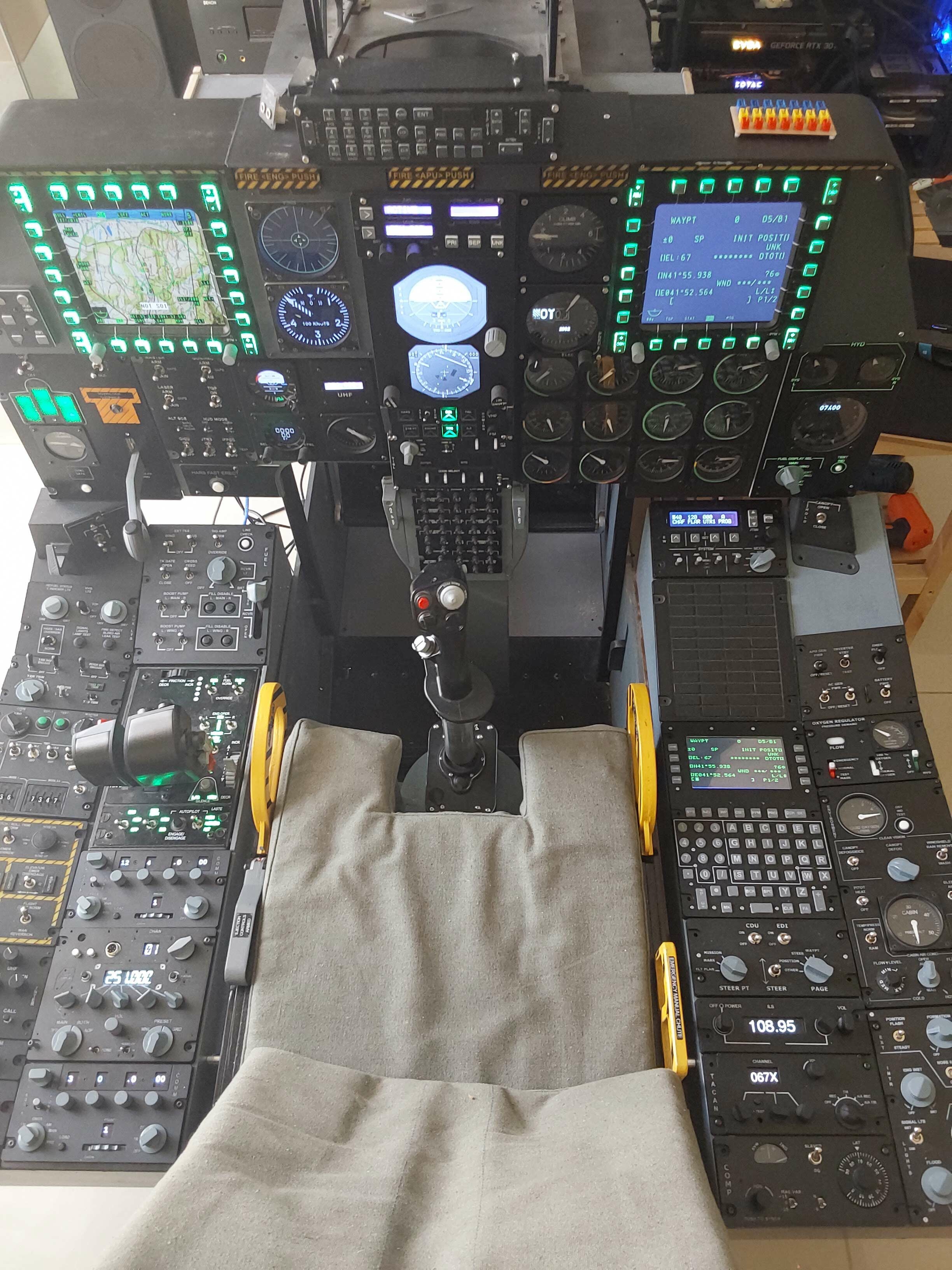
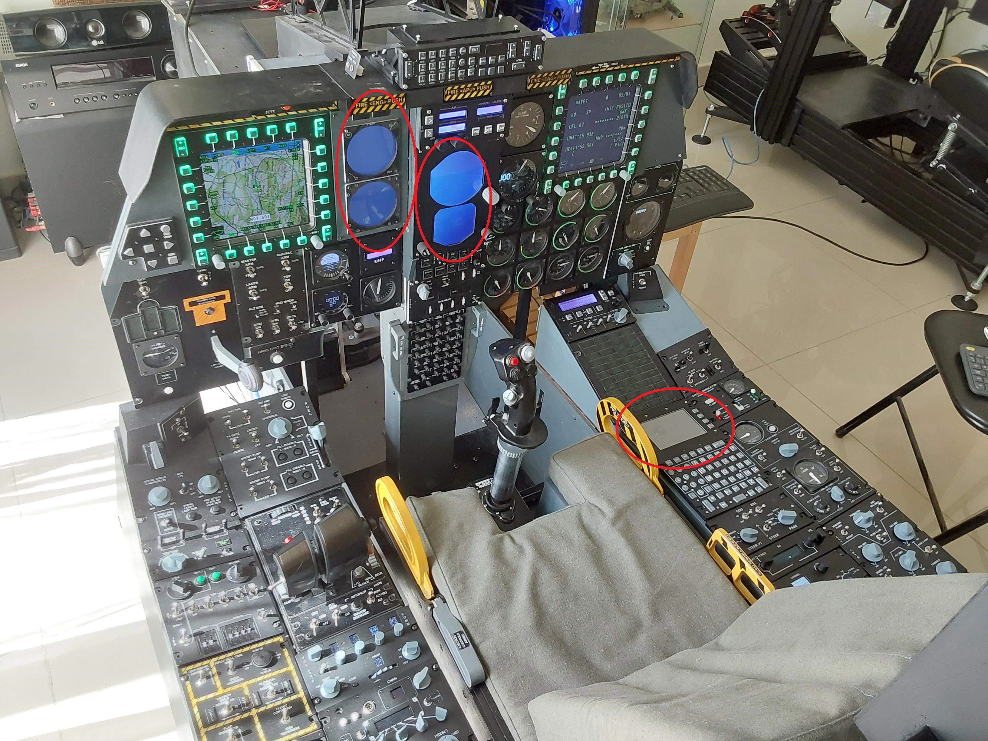
Unfortunately using Helios is another problem I will have to deal with. As you can see from the picture, I need to put the RWR and ASI on the left screen in the left hand red oval, the HSI and ADI in the middle one and the CDU in the right hand one. I can get the RWR, ASI, HSI and ADI to all display via Helios, but no matter what I try they remain dumb panels. I used to have them working before having to upgrade Helios after a reinstall of DCS. As you can see the MFCD's appear in their correct positions. I selected the CDU in Helios, but it shows nothing. Helios is supposed to be easy, but it's amazing how few up to date tutorials there are out there, and I have to say the same for the .lua setup for the individual cockpit instruments. The few I found are both out of date and don't work. I tried getting a generic A10 profile and then removing everything I didn't need, but there were so many errors and conflicts and issues that it was pointless. I couldn't copy a device and paste into my own profile, so that was a dead end too Cheers Les
-
Sorry guys, what is an OSB? On screen button? Thanks Les
-
Hi all, I'm trying to get the CDU and RWR displays to function on separate monitors using the monitorsetup.lua file. The MFCD'S work perfectly on their assigned viewports, but no matter where I place them the CDU and RWR do not display. I've tried displaying them in the middle of the main screen (x = 1200; y = 500;) just so that I can move them but they just don't appear. Can anyone post a working .lua file that shows the correct syntax and callouts for these two items? I would use the same setup for the A10C and A10Cii Thanks Les
-
It may be the type of potentiometer, some are exponential rather than linear - are you able to tell us the potentiometer type? Cheers Les