Snakedoc
-
Posts
305 -
Joined
-
Last visited
1 Follower

-
In my case I've partially fixed it by reducing the refresh rate of my screen to match the ones I have for the MFDs. I have the main monitor run at 120hz while the MFDs can do max 60hz. Setting the FPS limiter at 59 fixed it.
-
Thanks!! Haven’t quite settled on anything yet but most likely will be an AR setup
-
-

- 607 replies
-
- 12
-

-
@Vinc_Vega PFL = Pilot Fault List is another 5 lines 24 rows display just like the DED that is above the caution panel on the right hand console. it’s shows codes of various faults / BIT test that the pilot can acknowledge/cancel. in DCS at the moment it only displays very few info (I suppose it’s still WIP) but maybe it will be more complete in the future. it looks like it uses the same characters as the DED, so hopefully it will be supported by DCS bios and then it should be as “easy” as changing the snippets codes / addresses for it in your code
-
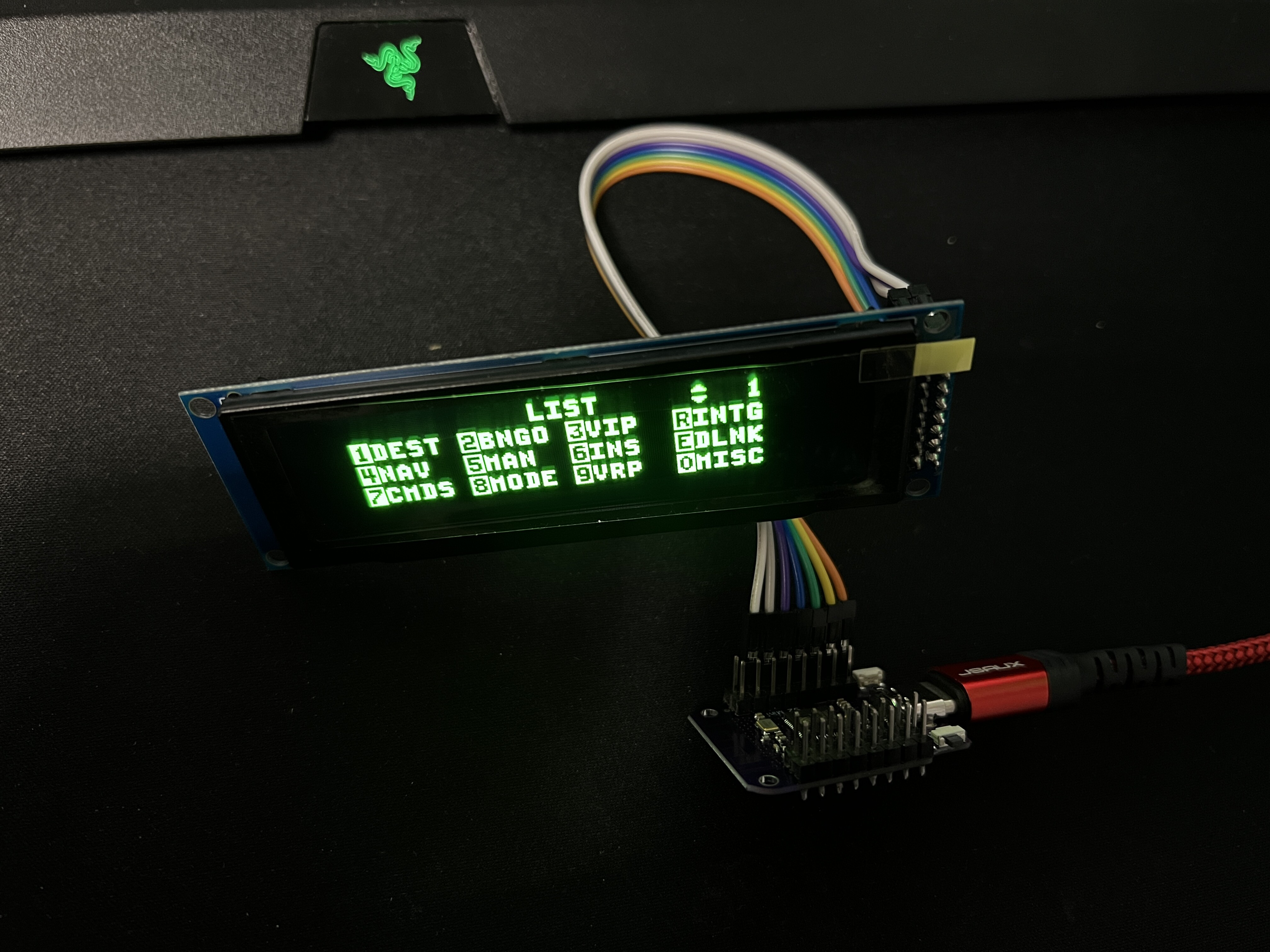
@Vinc_Vega Success! The display now works with pretty much 0 latency! Thank you very much for your help, greatly appreciate it! PS: you don't know by any chance if there's a way to use this code for the PFL display? I looked into Bort but couldn't find any snippets for that display, only the DED
-
@Dos The multiple-com-port calls for the same batch cmd file (connect-serial-port) so yes, it works I’ve tested it on my setup with no issues
-
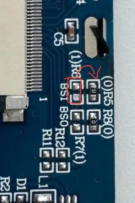
Yes my display arrived with R6+R8, so I changed it to R5+R8. the picture is from after the swap
-
Thank you @Vinc_Vega Looking forward to your findings! the connections are as you’ve indicated but still no output when I change to this driver by the way, maybe you know already but some of these screens don’t come by default as SPI, to make them as such you’ll have to re-solder a small jumper from “R6” to “R5”
-
Thank you Vinc, very kind of you I am still struggling though (screen won't turn on if I change the code as above) Couple of questions: 1. What board do you select in arduino ide to compile & upload the sketch? 2. my screen is an SSD1322, am I correct in setting this line up for the hardware SPI? U8G2_R0 or U8G2_R2? when I change this line and reorganise the connections, screen doesn't turn on Sorry for these noob questions, I am new to arduino & ESP in general regards
-
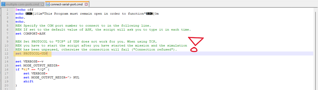
Happy to say that I've managed to have both programs working thanks to an amazing workaround found by @Ares63 (all credits go to him) In order to have both SOCAT & DEDHUB working you'll have to do the following: 1. open the "connect-serial-port.cmd" file found in your /SCRIPTS/PROGRAMS folder with notepad++ or similar 2. change the following line from "set PROTOCOL=UDP" to "set PROTOCOL=TCP" & save 3. as you've now changed the protocol to TCP, you must first launch DCS and be in an un-paused mission before you launch SOCAT! Otherwise you'll get an error 4. Enjoy your arduino panels & Simgears DED
-
I tried but even with those pins there's no change, it's still running very slow. I'll look into another board. Thanks for you help
-
Thanks @Vinc_Vega I did manage to connect it and have it detected, I was using the incorrect board type from arduino ide I successfully uploaded your code and it works!! Had to modify the "chip/screen type" line with the following as I'm using a 4 SPI SSD1322 256x64 oled If anyone wonders here's the pinout for an S2 mini board: Unfortunately the lag is very long, about 10 seconds before each line refreshes. I'm afraid it's asking too much out of the S2 mini Which board would you recommend?