Middlefart
-
Posts
79 -
Joined
-
Last visited
Content Type
Profiles
Forums
Events
Everything posted by Middlefart
-
Of course. I’ll try to fix that tomorrow and get back to you
-
Thanks Skickat från min iPhone med Tapatalk
-
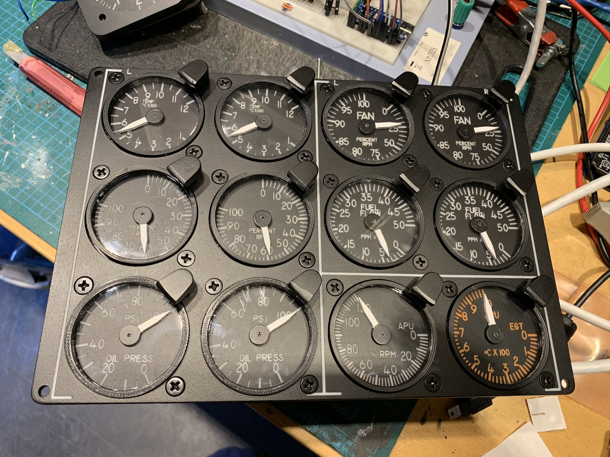
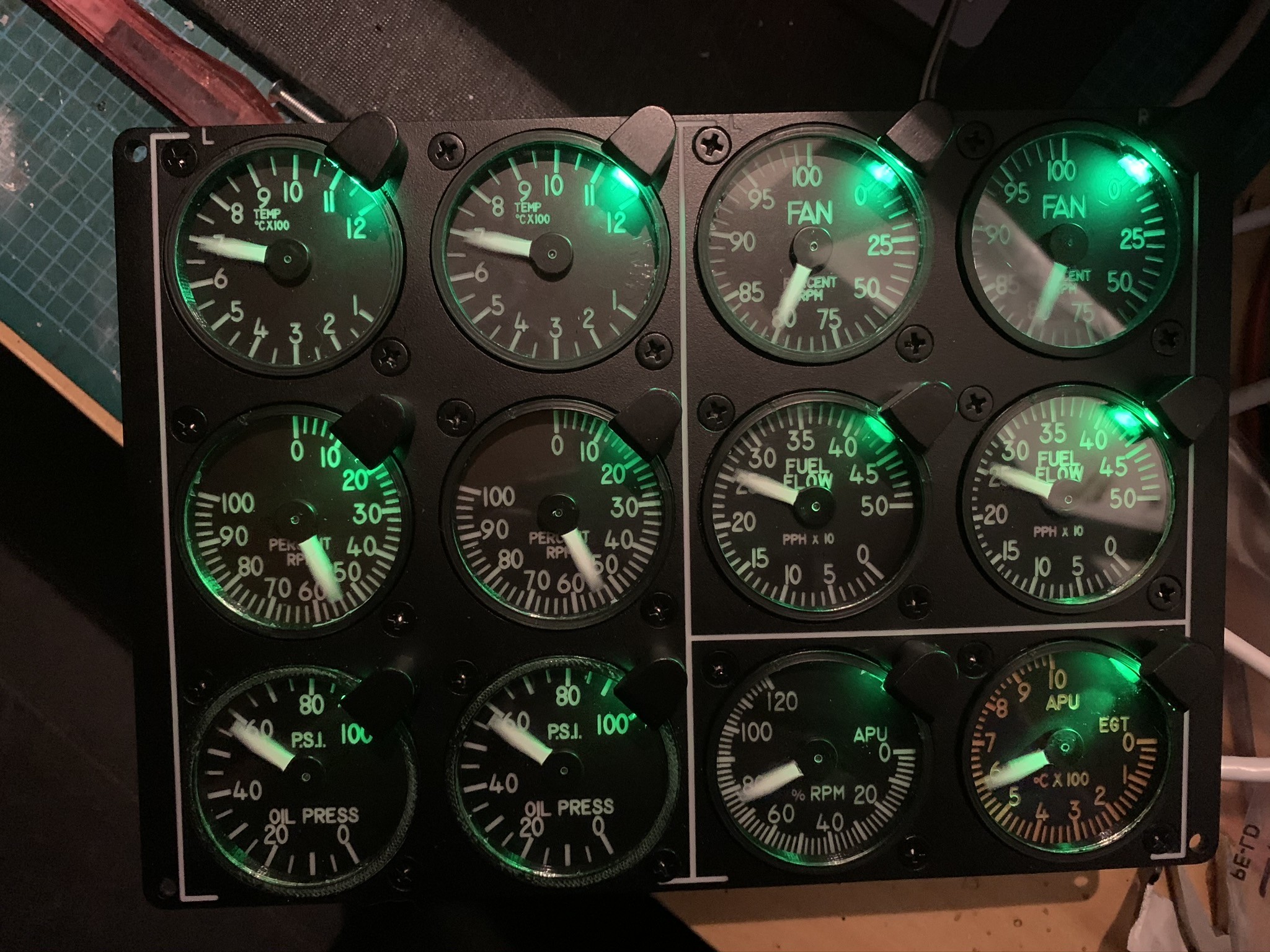
The engine cluster is finished

-
Middlefart’s A-10 build Sorry for late reply. I used Fritzing to design them and ordered them from jlcpcb.com
-
The pcb’s arrived today. Looks really good. Ordered them 5 days ago and got the shipped from China to Sweden today. Why did I bother with etching myself? :-)
-
Thanks!
-
While I'm waiting for my ordered PCB's to arrive I've started working on the altimeter. The plan is to have two OLED's displaying the altitude and the pressure in combination with the analog gauge. Really pleased with how this turned out so far.
-
And here is the PCB for the Master, Arduino Mega
-
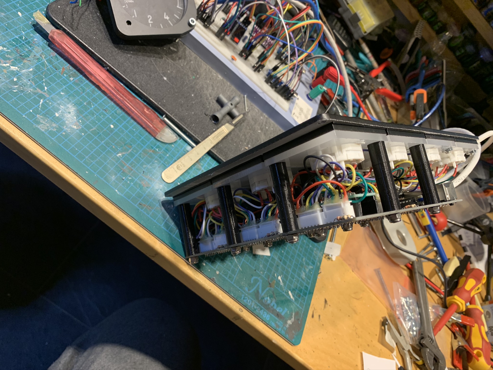
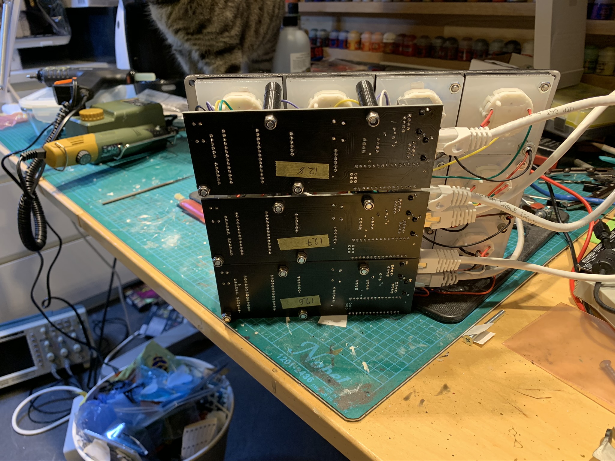
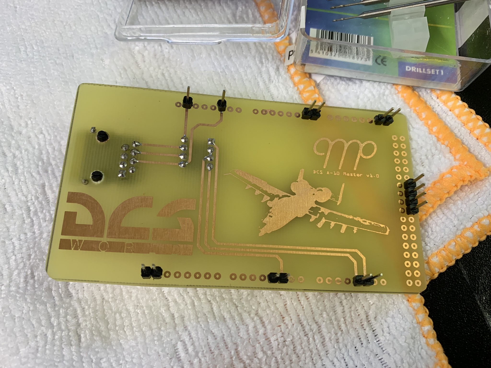
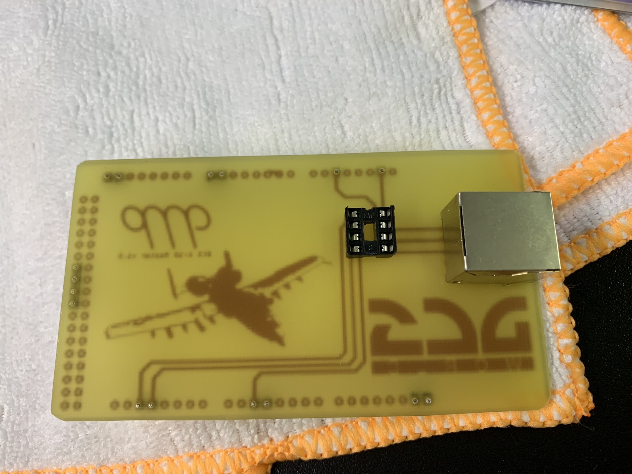
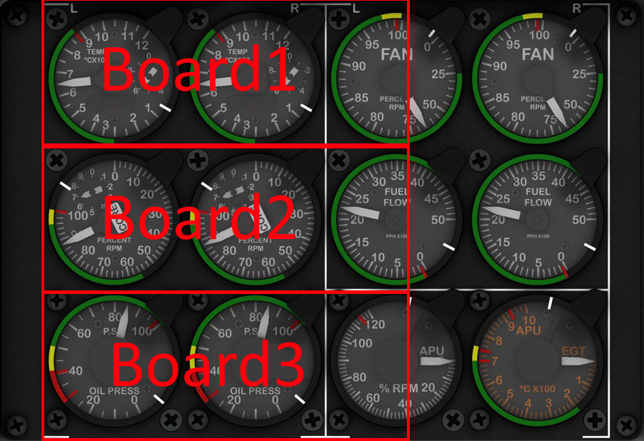
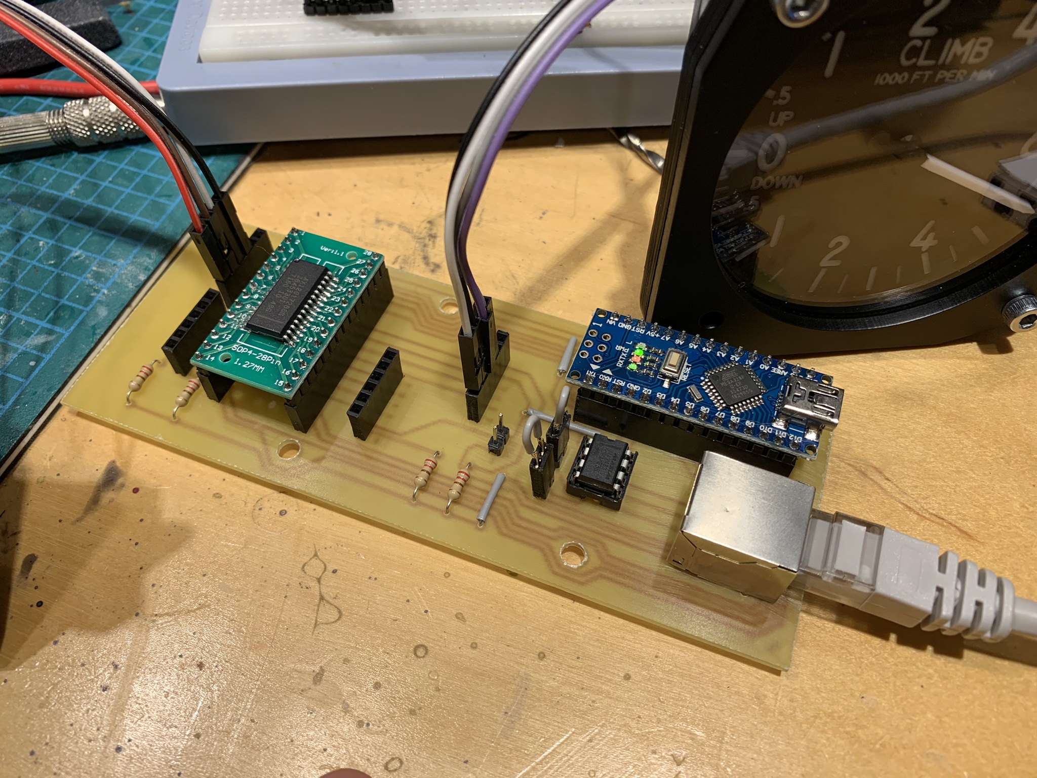
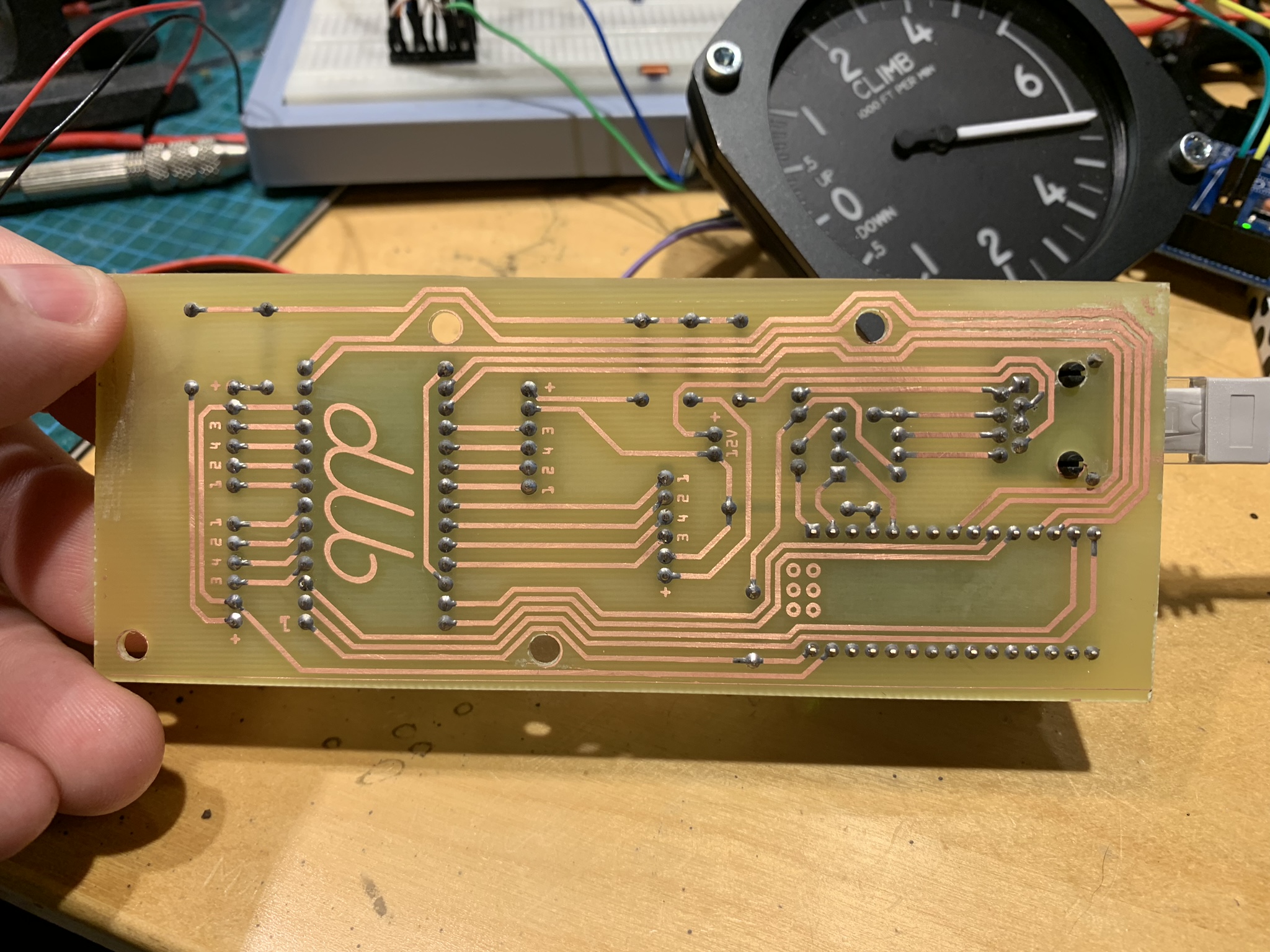
Here are a test PCB i made. The format is chosen so that it can be mounted horizontally behind the engine cluster. Each board can drive 4 instruments each. The complete cluster will need three of these boards mounted like this. The PCB is etched. I did order and receive a 3018 cnc mill but one of the drivers let the magic smoke out when milling my first PCB :-) Actually, I think i will etch the PCB's even after fixing the mill. It was a lot easier then i remembered. The ethernet cable provides the board with everything it needs: 5V Ground 12V (For future use. This board doesn't use it but i want my bus to have it if anything else needs it.) 5V for back lighting RX TX I have ordered JST XH connectors for the motors so the final board will have them instead of the 6 pin headers. Each motor connection has 6 pins. 4 used by the stepper and 2 for back lighting.
-
Have you looked at auto leveling to sort out the problems with uneven pcb's? (or is that what you refer to as bed leveling?) Looks promising. Will try it out as soon as I get the mill. And I think that double sided tape is better to use instead of clamps to hold the pcb down. But what do I know, I haven't tested it yet :-)
-
Yeah try a lower speed. How many mA are you cutting with? I've seen the method you are talking about, but I'm trying not to etch them at all. It would be great if the laser could cut the copper layer away :-)
-
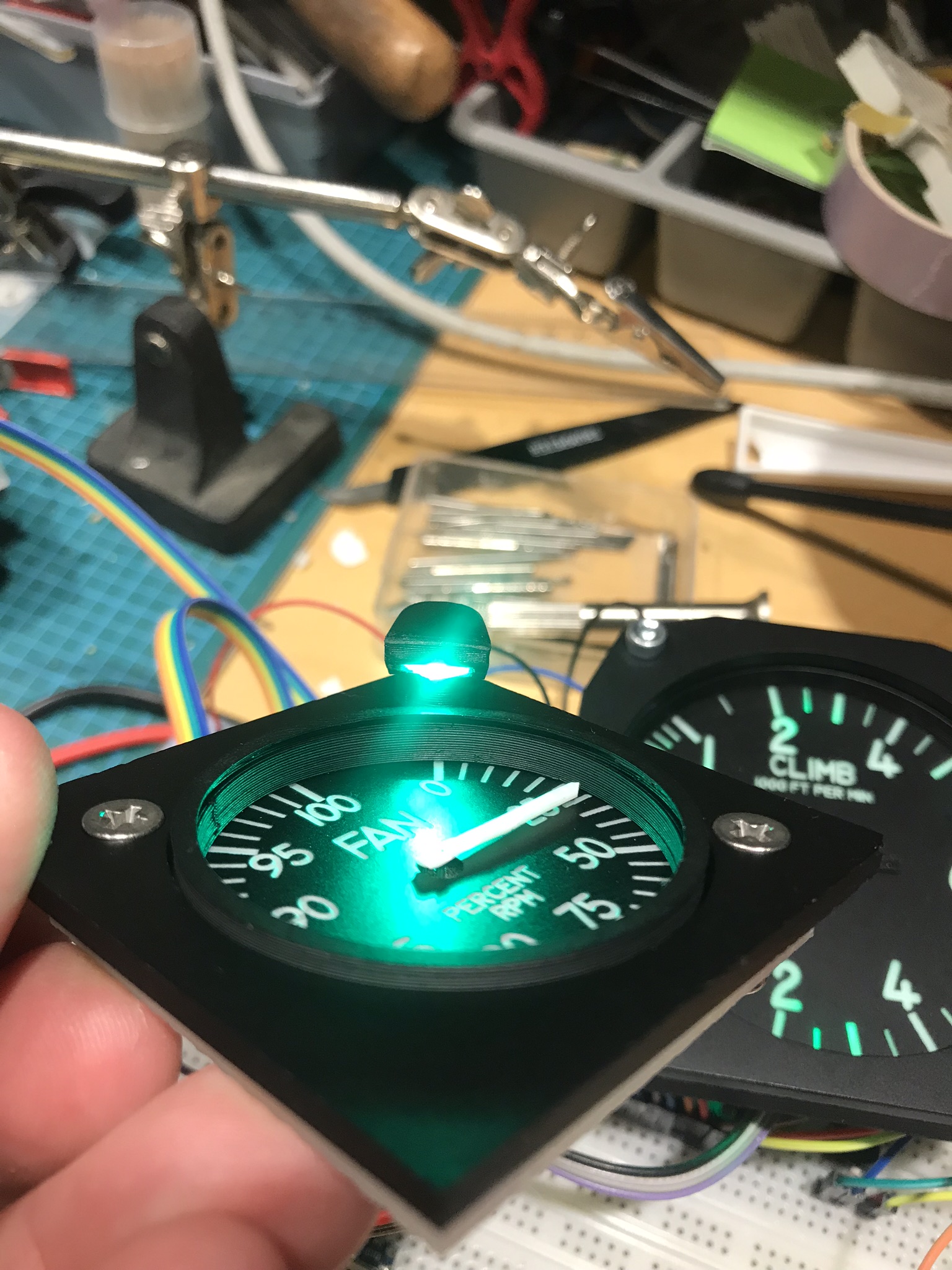
New version with light added. The engraving is a bit deep which made it a bit to bold. I've ordered a really cheap cnc router so that I can mill my own pcb's. I have etched pcb's earlier but that is a bit of a hassle. Hopefully it is easier to mill them. https://www.amazon.de/gp/product/B07MV846B4/ref=ppx_yo_dt_b_asin_title_o00_s00?ie=UTF8&psc=1 I'll start to build the complete engine cluster as soon as time permits. However I'm starting a new job in a week so I suspect time (and energy) will be a bit on the low side for the upcoming weeks. :unsure: The plan is to have 3 nanos running 4 gauges each connected in a rs485 network. The tests I've run shows no problem for the nanos to keep up so I'm feeling pretty confident that this setup will work. Since theese gauges isn't moving a lot during flight, a couple of missed steps won't matter too much :thumbup:
-
Thats sounds awful. My experience is totally opposite of that. After aligning the mirrors i was able to cut 3 & 4mm acrylic (any colors) without any problems. Haven't tested with mdf What speed are you running? I'm running 5mm/s 15mA for 3mm acrylic and 4mm/s 15mA for 4mm arylic. It ain't fast but it cuts it with one pass. Have you checked the focal point? https://k40laser.se/diy-how-to/setting-the-proper-focus-in-your-k40/
-
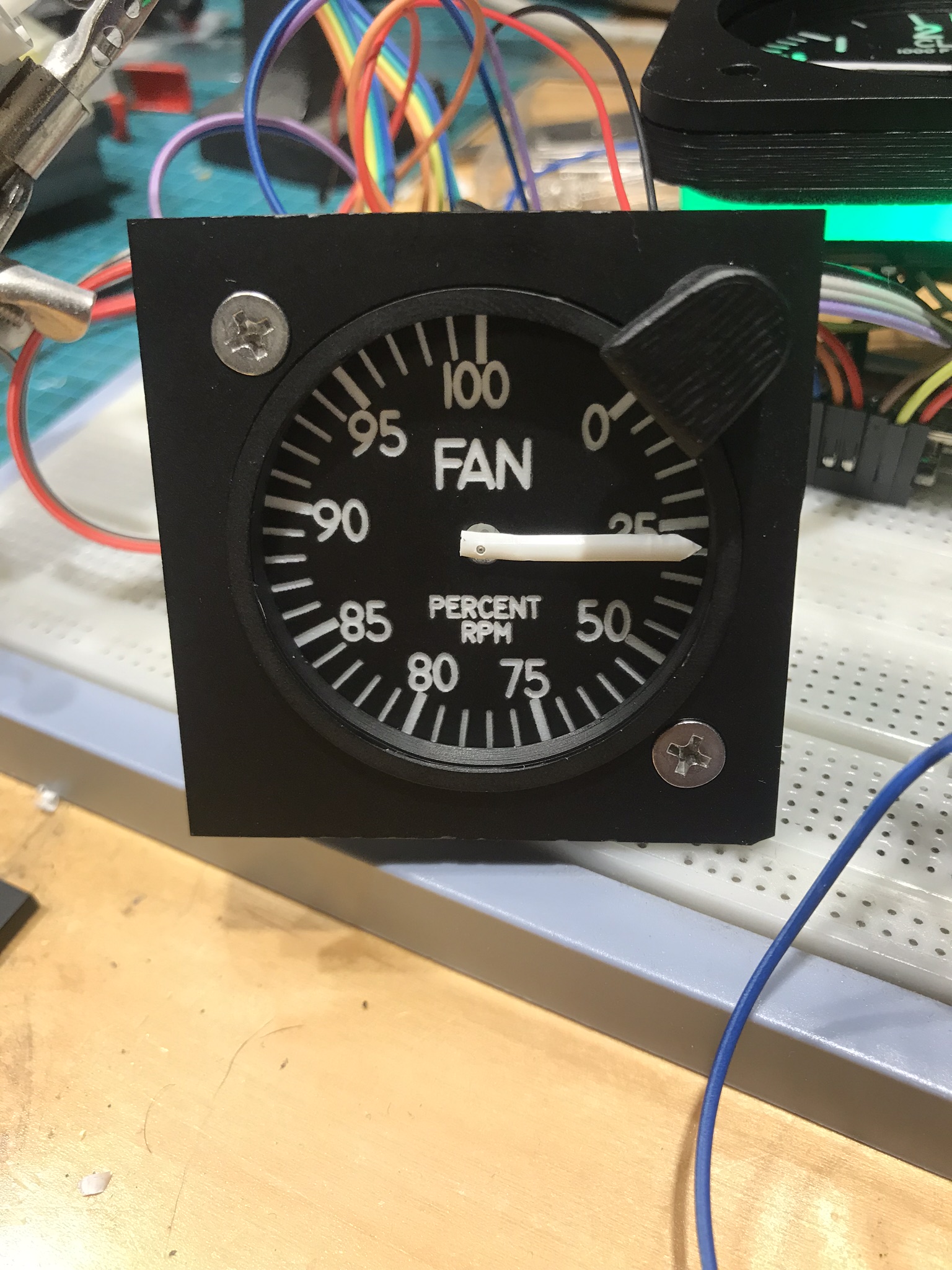
Here is my first prototype for the engine cluster. The bezel is 3D printed as two parts to be able to fit a glass. The needle is temporary. I need to find a good material to make them from. This will not be backlit since I'm planning on adding lights as the original has. Fusion file: https://a360.co/2NefXDa
-
Very nice. Would love some of those
-
Thanks. I tested it in a real mission but only for a couple of minutes. I didn’t see any signs of lag or missed steps but I need to test more. If I need to change it to one nano per motor, that’s not a big thing to do so I’ll continue this path and see how it works. [emoji106]
-
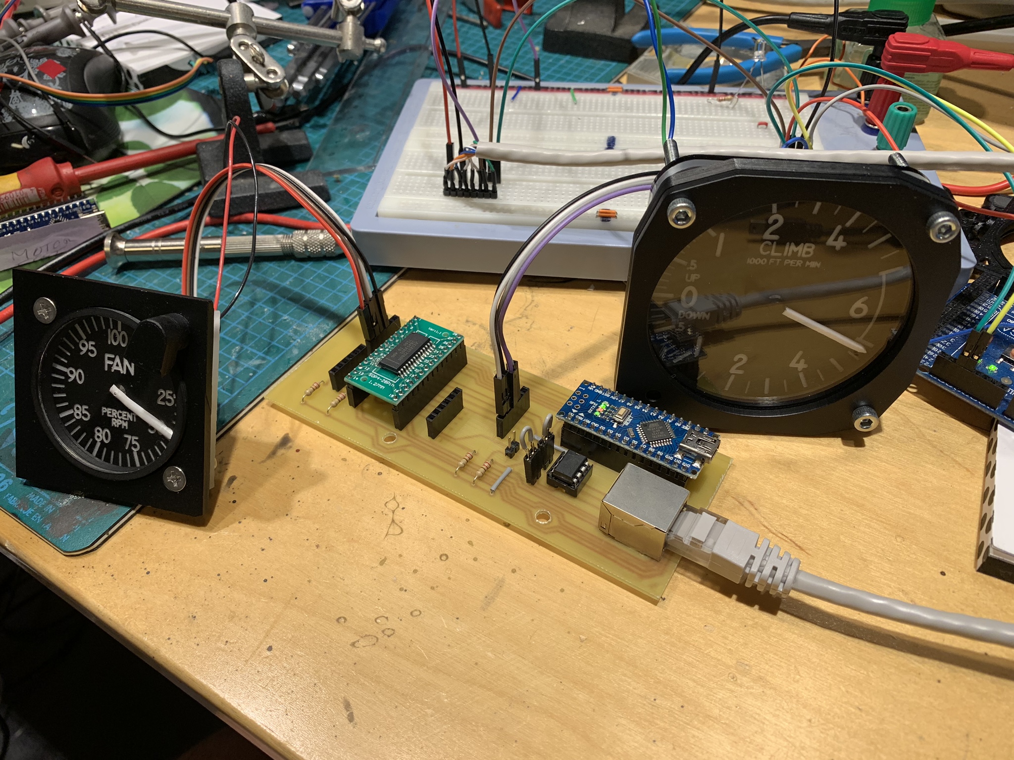
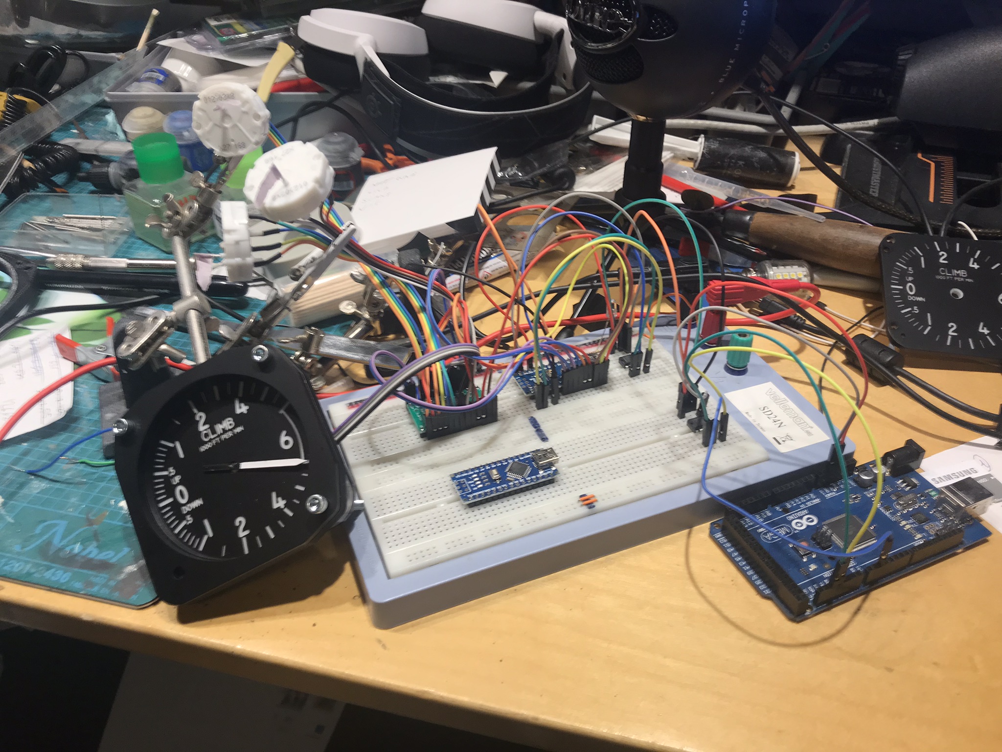
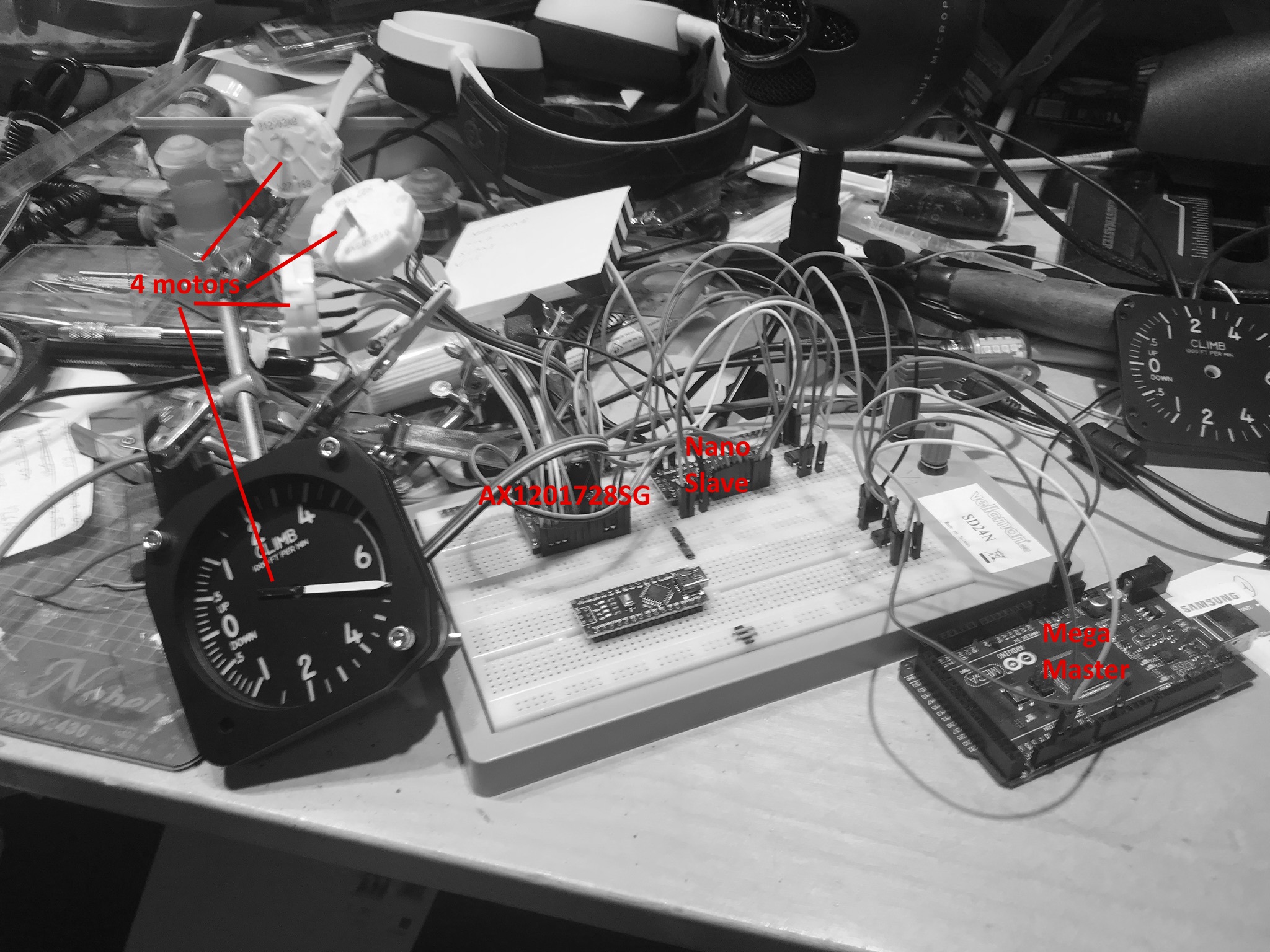
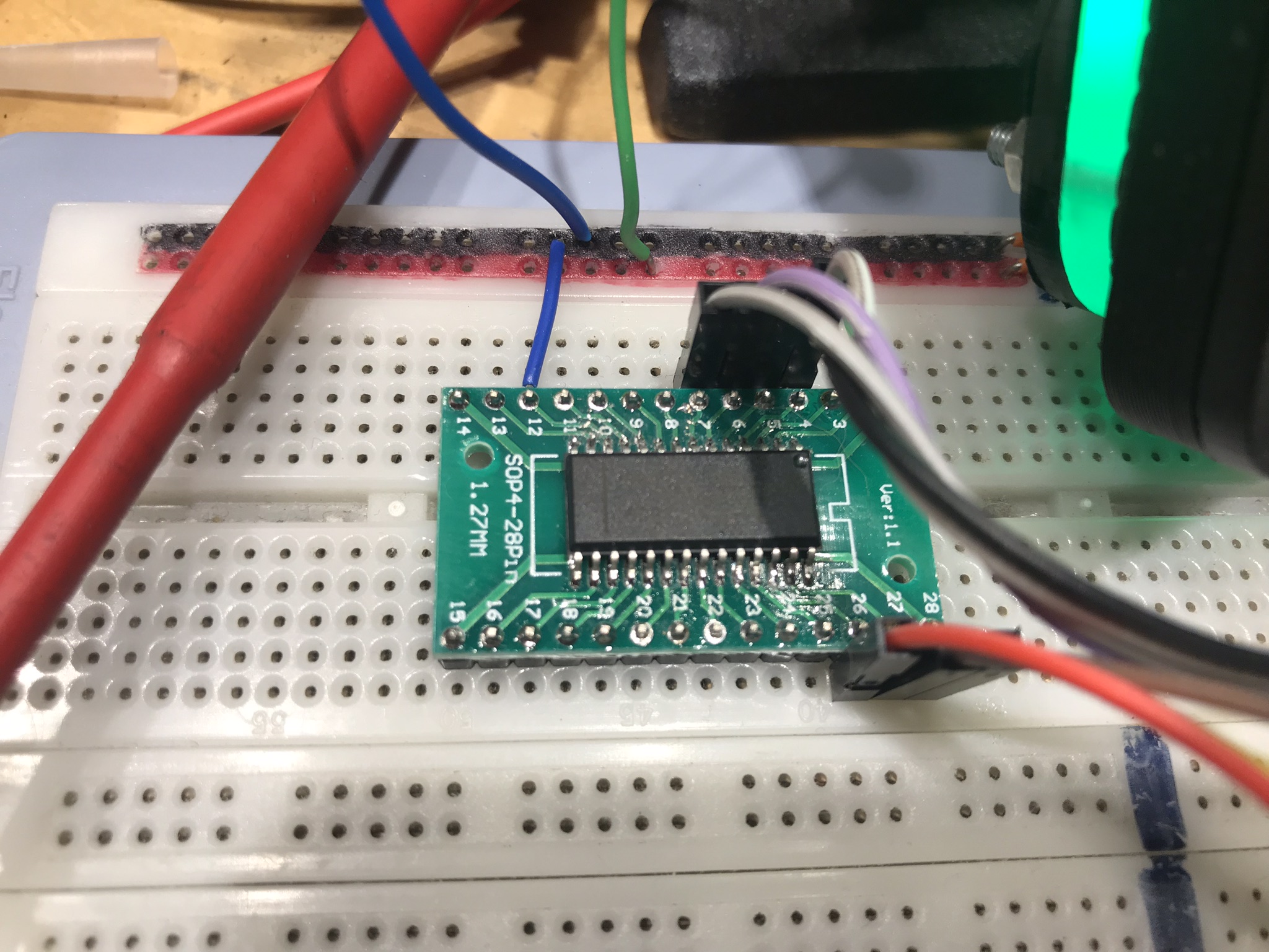
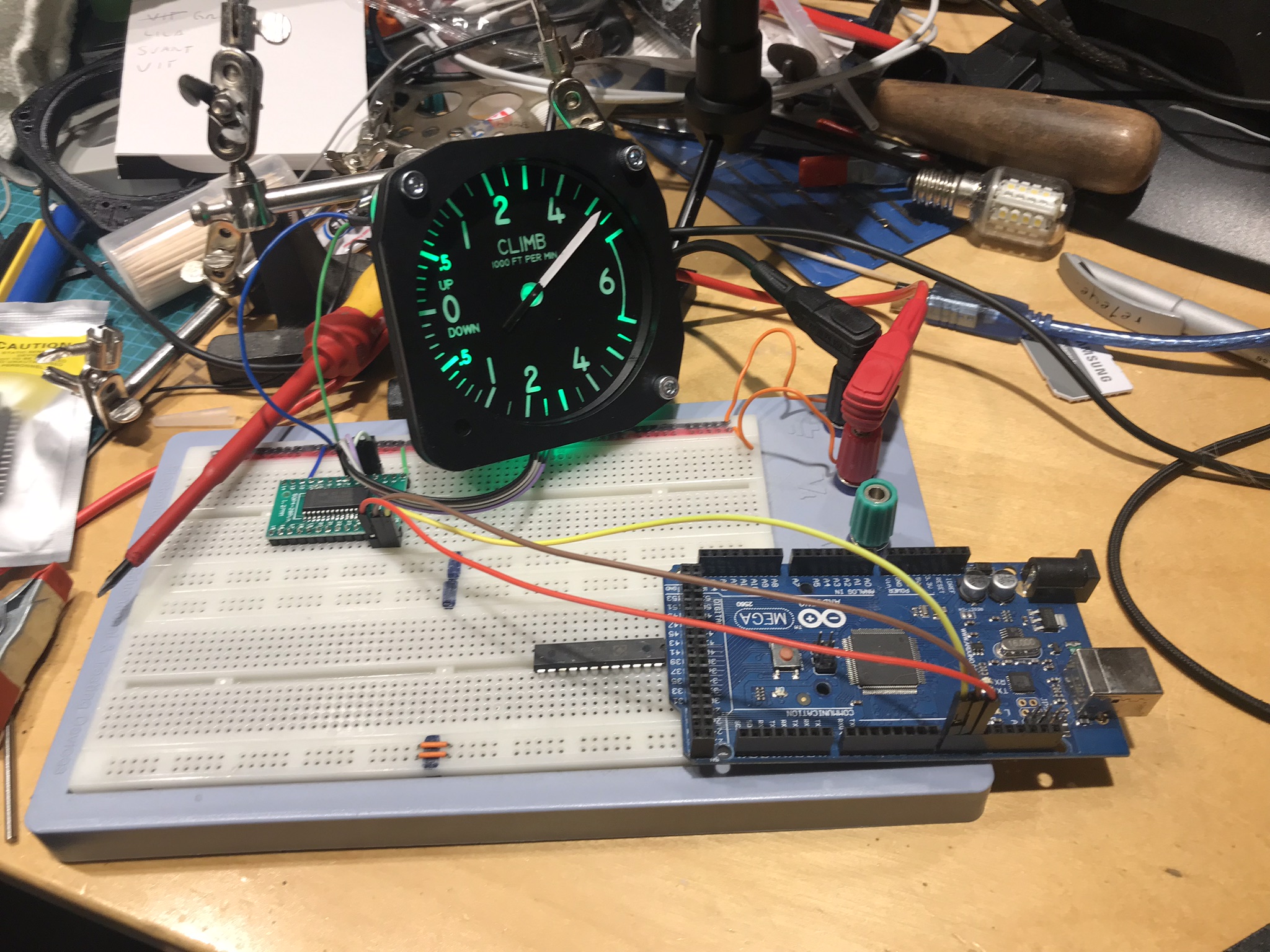
Today I've been playing with more motors to test if the Nano can drive 4 of them, which is what the AX1201728SG chip is supporting. This was no problem at all so I think that i will try to use one nano per 4 dials, at least for the engine cluster. I've also tested to run it on a RS485 network which also proved to be easy so that is what I will use. On my test bench I have one Mega acting as the master, one nano acting as a slave, driving 4 motors using the AX1201728SG chip. Works like a charm. I might need to clean my table :music_whistling:
-
All the 40w lasers on Ebay or AliExpress are more or less the same. There are basically two versions of them. An analog one where you regulate the current with a potentiometer like this one: https://www.ebay.com/itm/40W-USB-DIY-Laser-Engraver-Cutter-Engraving-Cutting-Machine-Laser-Printer-CO2/233296256862?hash=item36518a5f5e:g:reUAAOSwPdNdOZ4H and an "upgraded" digital one where you regulate the current with buttons. Don't bother with this one. I thought it would be better, but in reality it is worse. I converted mine back to analog and it is much better. This site explains it https://lasergods.com/k40-control-panels-analog-vs-digital/ What you want to make sure is that the Controller board is compatible with K40 Whisperer https://www.scorchworks.com/K40whisperer/k40whisperer.html. Most 40w lasers are but make sure that it is. The manufacturer is LIHUIYU for theese boards, ask the seller if the one you are looking at has a board from them. The included software is crap. Don't use it. Use K40 Whisperer instead. This is free and uses Inkscape (also free) to cut. You create the sketches in Inkscape and then open the file in K40 whisperer to cut it. Really easy. The upgrades that you must do: Better exhaust. The included one sucks (in a bad way, not the way we want it to :)) Add air assist. This blows air at the cutting point making sure that the fumes are blown away and doesn't clog up the lens. I've also added a flow sensor so that the laser cannot light up if the water isn't flowing. https://k40laser.se/k40-parts/k40-spare-upgrade-parts/cooling/water-flow-sensor/ and some laser pointers so that i know exactly where its going to cut. https://k40laser.se/k40-parts/k40-spare-upgrade-parts/electronics/red-dot-laser/ I've also replaced the original bed to get a bigger cutting surface. These sites has some good tips. https://lasergods.com/beginners-guide-to-the-k40-laser-engraver/ https://k40laser.se/faq-how-to/ I can take some photos and make a video about my laser if you want me to.
-
Middlefart’s A-10 build Sorry, have been busy for the last couple of days and haven't checked this forum. It's hard to get a good picture of the edge but I would say that it is a very clean cut. This is a scrap piece I cut.
-
I'm using a 40w laser from eBay. https://www.ebay.com/itm/113647723513 Needed a bit of tinkering but now it works like a charm :-) I don't recommend bying one of theese "upgraded ones". I replaced the upgraded parts (the buttons and display) with a potentiometer and a mA meter (which is exactly what the non upgraded ones have) since they give a better understanding of how much you push the laser. You don't want to over drive them
-
Thanks, I try to only remove the paint but it is possible to burn into the acrylic if you want to. The laser is also used to cut the acrylic.
-
Here's a link to the Fusion 360 project https://a360.co/2YqX2vr
-
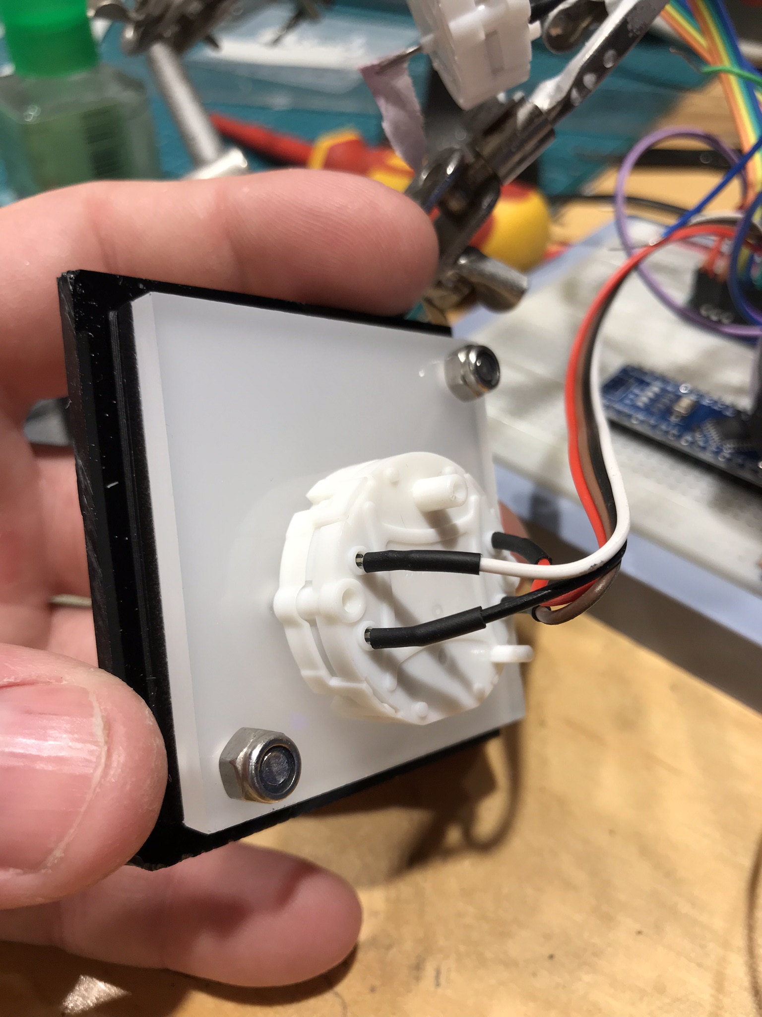
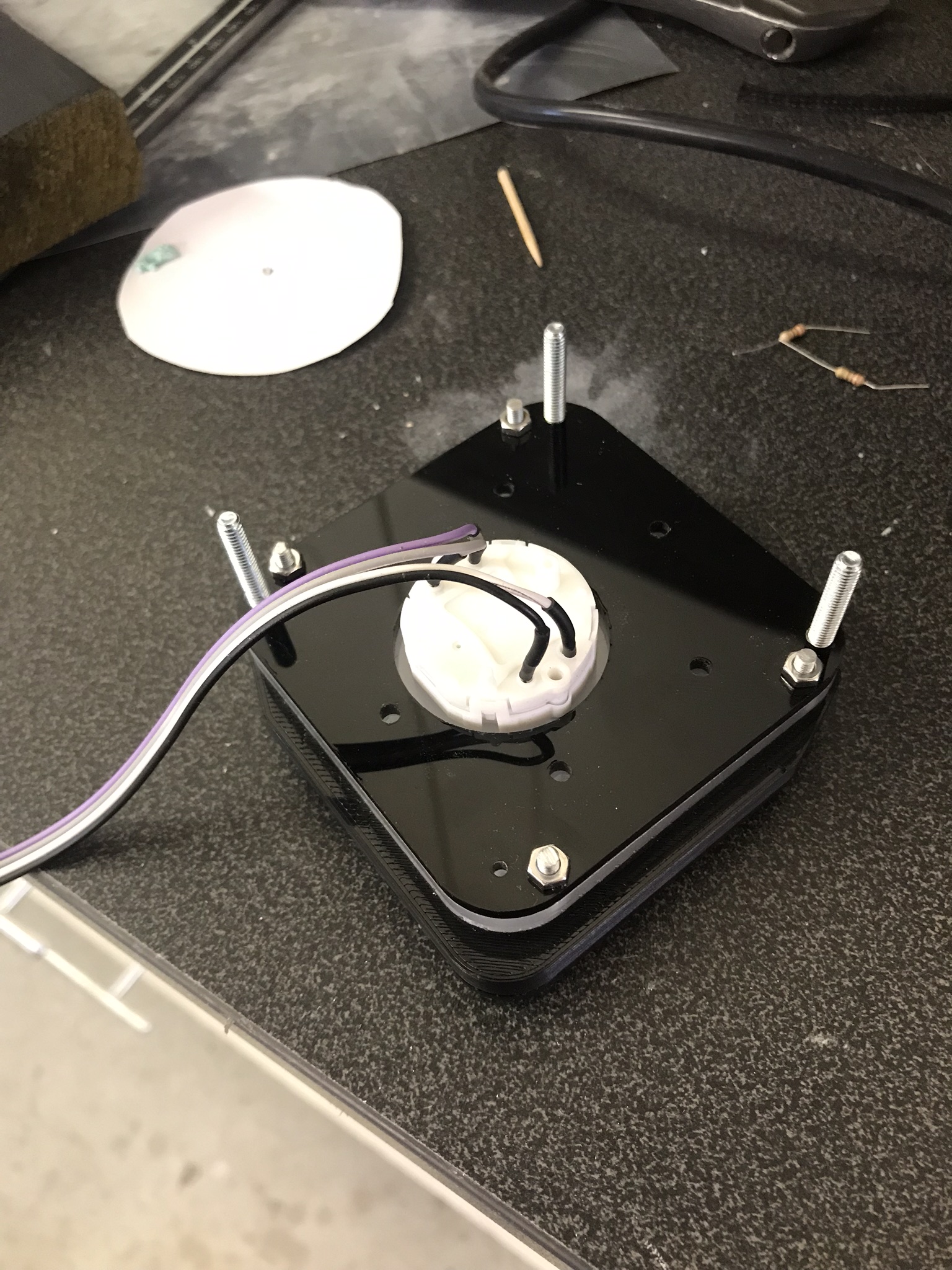
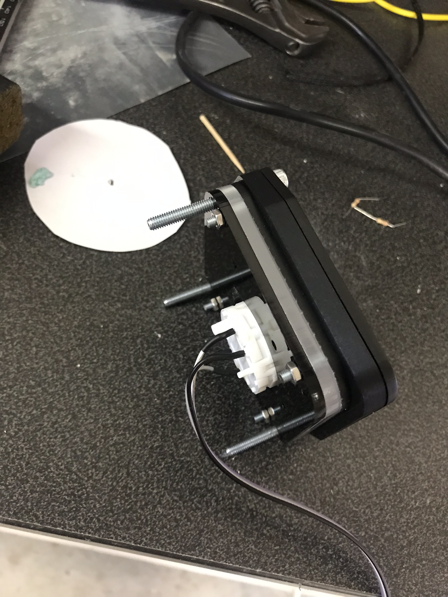
Thanks! Here are some more pictures. The motor is driven by a AX1201728SG driver chip which can run 4 steppers. It only uses 2 GPIO pins per motor and has microstepping with 12 steps per degree. I use the SwitecX12 library and rewrote the code for dcs bios to work with this library instead of accelstepper which seems to be what everyone else use. The reason i went this way is because I already had the chip https://guy.carpenter.id.au/gaugette/2017/04/29/switecx25-quad-driver-tests/ Currently its all connected to a Mega but that will be changed to a Nano later on. The photos of the back was taken before i added the back lighting diodes. The grey-purple-black-white wire goes from the driver chip to the motor and the yellow-brown-red is a reset pin and the two pins to run the motor.
-
Thanks! It calibrates by first mowing fully left where the motor has a stop. IF the motor doesn’t have a stop, it can do full turns, you need to ad a sensor that can get the position of the dial, for example an IR-diode or a hall effect sensor and a magnet. Skickat från min iPhone med Tapatalk
-
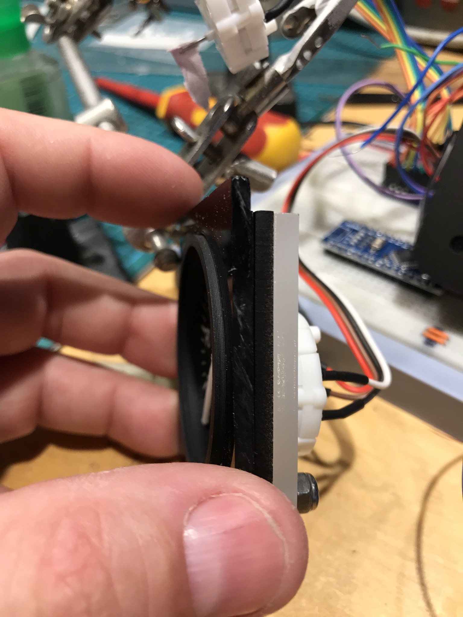
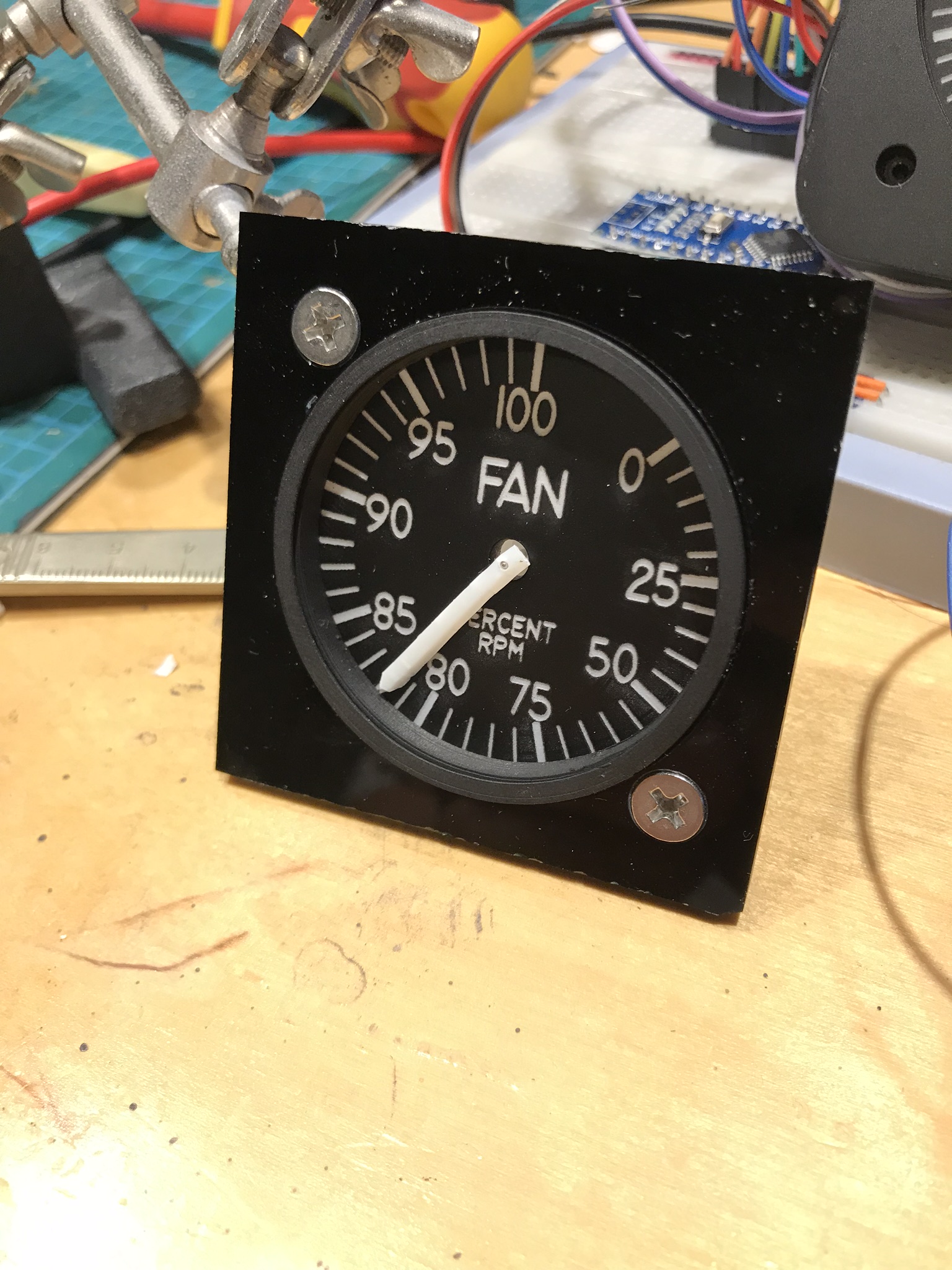
The first version of the VVI is finished Can be backlit, but i haven't soldered in the LED's yet. The dial is temporary (cardboard) and the glass is missing. It's based on a x27.168 stepper driven by an Arduino mega (going to be a Nano over rs485) with DCS Bios. It's built from 4 layers of acrylic and a 3D-printed part. Really pleased with it.