Gadroc
-
Posts
1060 -
Joined
-
Last visited
-
Days Won
1
Content Type
Profiles
Forums
Events
Everything posted by Gadroc
-
One other thing to keep in mind is you'll probably need to gear up the movement in order to get full range on a sensor. I have a similar setup and only register 800-1000 steps of 4096 available on my controller.
-
Y2kiah, that is something I meant to bring up as well. The DXF are messed up on those. You don't have a full outline of the actual part, you have outlines of the pockets and of the non-pocket parts. Also the pocket cuts need to be extended to account for radius of the milling tool so you don't end up with little bits in the corner. So you need one polygon of the full outline and then separate polygons for the pockets and the pocket polygons should extend by 1/4" outside the profile cut.
-
Yes pretty much. The only thing you have to worry about is making sure your wood thickness is .75 inches and not .703(18mm) so the pockets fit right. Other wise you'll have to make some modifications. I have a version that is setup for 18mm thickness material, which I'll try and get posted up tonight. I would not want to try and hand cut these plans, and you would likely spend more in labor than in a CNC shop (I guess depends on your local market).
-
All the circuit boards are assembled and have the firmware loaded up. Next up: [TABLE]Task|Estimated Complete Solder up display cables|12/31/2011 Sand down flanges on buttons|1/1/2012 Final light plate assembly|1/3/2012 Wire up boards|1/28/2012 Shipping|2/4/2012 [/TABLE] It's taking a little longer than I wanted due to a shipping delay on parts as well as a nasty sinus cold last week. This means I won't get them done before a family vacation which is pushing end dates out by a week. I'm going to be just outside my 8 week delivery schedule and I'm sorry about that. I'm just as excited to get this bad boy in my pit as you guys and I"m not cutting and gluing mine up until yours are shipped.
-
Very very disappointing!
-
Progress Update: Buttons are completed. Now that I've completed a working firmware and tested the first circuit board I'm now assembling the rest.
-
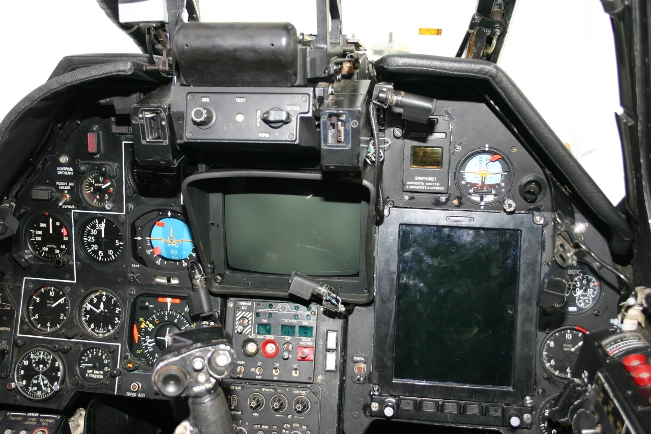
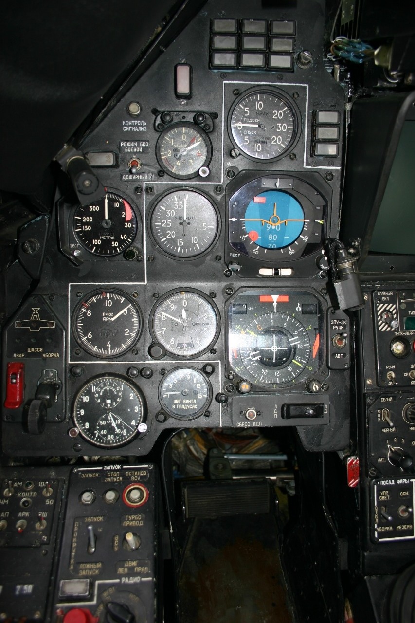
Here is a pic of the left hand side of the center panel which may help. Also I've attached a picture of the full CP. To get dimensions take something you know the size of (ABRIS screen is 10.4 4x3 screen if I remember correctly) and extrapolate what size other things are relative to it.

-
Looks like a good start. A couple notes. You missed holes for the master caution and rotor limit indicators. Also you're gauge holes on the left side look to close to the ADI and HSI, that will be very hard to make, might want to look at spacing that out a little more. Lastly you need a hole for the landing gear panel as well.
-
I dont think it will work. Once you have the panel mounted there will be very little light behind the panel making the text very dark and hard to read during the day.
-
Excellent recommendation, I always make a search one Viperpits when I start a new project. Also should mention Mike Powell's books and website.
-
I got the right console cut out today. Here is a short video of the CNC machine cutting it out.
-
Then you really haven't looked very well. LOTS of info on this forum. :) Definitive, nope. There are several people who have posted there work but you will not find a definitive guide. Here are the most complete plans available. Y2KIAHs pit plans (I'm using these). Dimebugs Stencils these are also nice, and potentially easier to do with out a CNC machine. I have posted a sketch up version of his plans in my threads and at scsimulations.com. Flim and I used to sell them at scsimulations.com but we no longer sell any kits. Flim no longer has his CNC machine, but is looking at a way to sell a kit to cut your own. Again no definitive guide. Several folks have posted their panels through these threads. I'm currently going through and creating mine (based on pitblders work but making them adhere to mil-spec sizing). I will be posting all of my CorelDraw files as I complete them. Nope, not necessary. DCS does not support multiple PCs rendering the game at all, but you can use a remote machine to render gauges via Helios. MFCD displays and RWR must be rendered on the main PC running DCS. Check out pitbldr and y2kiahs threads. Won't work unless you have special printer (printers don't normally have white ink and can't print white). Getting LEDs to shine through thin white acrylic is not a problem, the biggest issue is getting the light to diffuse enough to get even lighting. This is not an easy problem to crack DIY. EL Sheets give the best results but get very expensive. You can check my build thread on details how I'm making my panels. There are also several threads of people making panels by printing out and laminating.
-
Anyone not seen Helios in Action with DCS A10-C
Gadroc replied to Loz's topic in PC Hardware and Related Software
Be aware that you will not get RWR, or MFCD actual displays on a networked computer. Helios does not render those. You can render the bezels but not the actual displays themselves. DCS is the one that has to draw the MFCD displays (they are actual 3D renders of the game world and not reproducible outside the game engine.) -
I am using screens I bought from Vitrolight when I was going to make an F16 pit. I have three 8" (two for MFCDS and one for ADI/HSI) and a 5" (RWR) all with a vga boards. I will be buying a 3.5" vga screen when I design my CDU as well. They will all hook up via a 5870 eyefinity 6 card. I will probably be going down to a single external 46" tv for the pit for performance reasons. HOP_TRIZZ, be aware that not all LCD screens are the same. The VGA board has to be programmed for that specific screen and there are several different signaling methods. Don't just buy a LCD panel assuming you can "just buy" a controller for it. Do some research first or buy a set.
-
I've been laid out by my annual Xmas Sinus Cold the last few days, so I've only been working on electronics. I'll be cutting right console next week. I need to tweak the front panel to fit all my LCD screens anyways.
-
Sure. I'll hold my breath and you let me know when NVIDA releases a video card that doesn't require SLI for over two monitors. :thumb up: Don't get me wrong NVIDIA has some great cards for stock gaming configurations, but they really really fall flat when you are trying to put together a cockpit that requires 4+ video outputs.
-
All the values are on the schematic you can find here. As I've said before EOS is not a pick up and play kind of setup. If you don't have a rudementory skill set at least to be able to read a schematic you will have a rough time of it. While I love to help people you'll have to learn some basic electronics on your own.
-
Also you will have problems finding LCDs to fit a real front panel. There are not exact LCDs available to consumers for these dimensions and you'll have to cut the frame to hell and back. When you see home made cockpits they usually have fudged the dimensions a little bit (a quarter inch here... an 1/8th inch there) to accommodate the LCD displays or home made instruments and panels. Retro fitting this to be a A-10C is no small task, especially if as you say you're all thumbs. Fabricating this type of stuff is an acquired skill (I'm just starting to learn it). I'm not sure I'd start off my first project with this. I'd highly encourage you not to start just ripping things apart and modifying. This is going to take you a long time and you should do a few panels and things out side that very nice SA Trainer to learn first.
-
The CMSP panel can either communicate directly to a computer via an RS-232 Serial to USB cable, or it can connect to an EOS RS-485 bus controlled by a EOS interfere shield via a twisted pair wire. Either way the panel speaks the EOS protocol which is contained with in the EOS Libraries. I will be publishing more on it later. The CMSP panel is the first real panel and it will flesh out the validity of the protocol. I will also be publishing a .Net library and command line tools to interact with EOS boards either via direct serial or your own program. Lastly I will create a GUI in Helios to configure and bind EOS boards to simulations.
-
Yes you can handle it that way. I'm not sure you can do it directly in DCS, but it's easily accomplished in either Helios or XPadder.
-
Ok. Have the CMSP panel sending back analog data to the computer as well as all output controls going. Here is a quick video.
-
Unfortunately I use LaserMax for the faceplates instead of just engraving through paint, so repainting and engraving is difficult. Also one of the limitations of the "cheap" laser I got was it's horrible cutting bed. I have to manually remove and add shims to change the bed height. This means the laser grid (aluminum egg crate) is not fixed so there is no way to create a jig for registration, so no touch ups. It's not really a big deal, I should have checked better before cutting them out. At least it's only the faceplate and all the already painted parts are fine.
-
Thanks. BTW I just found an error on your the CMSP... you have NWS instead of MWS. Off to re-engrave and cut the faceplates :music_whistling:
-
Wow. I should treat it better. For that kind of money I might be willing to part with it Glad I got it before it went out of print.
-
Thanks. Also here is a shot of some unmanaged wiring while I work on the firmware.