Jocman
-
Posts
205 -
Joined
-
Last visited
1 Follower

-
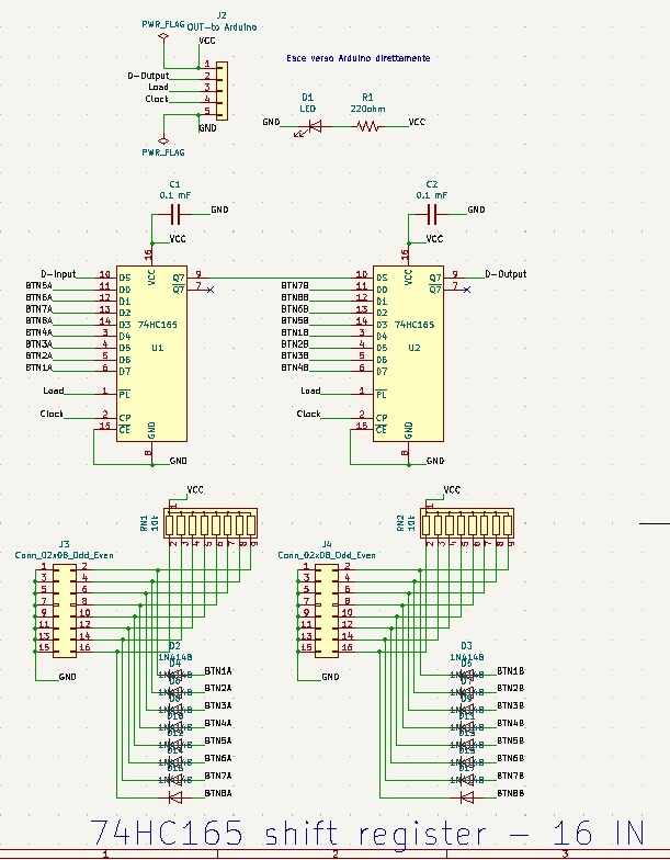
Hi all I'm going to test a freejoy board fo my cyclic-collective-pedals controls in BS3 For the sake of honesty, as I'm getting some problem with freejoy, I'm thinking to switch (temporarely) to a Leod Bodnar USB card, but the idea is to use the system as I designed. The master idea is to use shift registers for cyclic/collective buttons/switches (meaning 2 "5 wires" cable coming from each control, instead of X-wires), while the analog axis (hall sensors) processed by DAC/ADC converter. I realized 3 PCBs (attached 3 schematics): - Cyclic (2 shift registers) - Collective (3 shift registers) - Freejoy (for STM32) As you can see (my "error"), I wasted a lot of STM32 pins, without considering the possibility to connect other buttons/switches/LEDs/etc etc, but it doesn't matter.... Hall sensors: currently, the only control done is the collective. It has 3 hall sensors: - Collective: hall sensor pot - 2 throttle levers, with a magnet and a hall sensor each After flashing the STM32, it has be recognized by windows. I tried by connecting a single throttle just to test, but no sign of life from the axis... Then connected the main cable (to the shift registers PCB), but again no sign of life from the buttons.... More, the SMT32 "switches" off continously (disconnected in the Freejoy configurator V 1.7); this happens both if the STM32 is PCB mounted or not.

-
Hi all. I'm trying to develope a Freejoy controller for my cockpit and built a PCB. I'm getting some problem, so I'm wondering if I'll post some description and PCB diagrams, is there anyone who could spent some time to help me to fix it (or at least try to)? Thanks in advance
-
Hi all. After upgrading to last version (honestly, about 6 months I didn't launch DCS...), I'm getting a "login failed" message, because the web site is unavailable. Anyway I can keep going on offline with a 2d 23h 49m authorization and with no multiplayer allowed. Honestly I'm not flying for the moment, just making some test for my home cockpit, but what will happen after the time limit? Any solution? Is this a general problem or it's my problem? Thanks
-
My 50 cents.... Steering dampers work great for me. Actually, as my collective is quite....."ponderal", I'm testing with more than 1 damper (the lever is a little bit long and the collective switch box is not very lightweight). In the pic you can see the initial frame i built for the collective. Currently, I added an electromagnetic brake to keep the collective in position, so I think i can revert to the original 1 damper
-
My usual 50 cents...... Yes, it's the classic budget one. I got one about 5 years ago, made some test (my goal was to use it in conjuction with my cnc to build my panels), then just left it waiting for when my cockpit will be done and functional. Why? because need it more time to get the Tool (with capitol T) I want. It's a nice tool, indeed, but very basic....I played with it for several months, upgrading and changing almost all.... have a look of what I changed 1) first of all, switched from a digital power management to an analog one. Why? first 'cause the original digital one is not so calibrated, then 'cause this way you get more control on the laser power (and is not a secondary matter....) 2) the gantry is very poor....Well, it works, of course, but the movements are not so smooth and precise: if you use a laser (meaning, you want a precision job), but move it on a mule track instead of a race, smooth track? Again, the area is not so broad, limiting your job dimension. Thus, I disassembled the old gantry, moved the electronics on an external box, and started design the new, extended, gantry. Of course, using some better rails than the original (very cheap) ones. And even a self adjusting Z axis work table. But, works still ongoing (until my cockpit will be finished) 3) changed all the wires (expecially the ones for the high voltages managing the laser side), 'cause the original ones are really, really a crazyness! (if you think my original K40 had no ground connection....) 4) the electronic: changed the original controller board (very limited) switching to a digital one (a ruida one - no way, another planet!) 5) Increased the safety: emergency stop, laser separated key switch, safety lid switch, flux meter (if for some reason the cooling fluid stop working you'll burn everything), inlet / outlet temp sensor, bigger fume extraction pump (useless to say the fumes are not so friendly), air assist (very useful for the fume / burning prevention), and other similar stuff. 6) some other minor stuff In the end, from the original K40, I kept only the laser tube and the box....Not really cleaver; and most of all, not cheap.... but if someone (like me) loves tinkering with stuff, it could be a good "toy". So, going back in time, maybe I won't get a K40. In my plans, after all the replacements, maybe (maybe) I'll get really a good and versatile tool. If you are not so "tinkering-lover" (and don't want to pay more) I'd suggest to have a look to the new (almost new) fiber lasers: honestly, I didn't get into these new stuffs, but they seem to me functional and the price (at least for the basic line) is comparable with the one you report. Hope this may be helpful. Cheers
-
Hi all. Just finished wiring and testing my front panel (except for the Ekran), and it seems working fine. But I've a little problem with the ADI knob. It should turn L/R just a little amount (about + - 30 degree), but no way to make it work. More precisely, it works, but the movement is too short to be effective (I can see the virtual knob moving an infinitesimal step.....but not the full 30 degree range) I tried (experimentally) to modify the encoder resolution in the snippet, I tried up to the max (+65535 -65535) but the max rotation is maybe 1 degree The standard Bort's snippet is DcsBios::RotaryEncoder adiPitchTrim("ADI_PITCH_TRIM", "-3200", "+3200", PIN_A, PIN_B); I tried from (it works great for the HSI) DcsBios::RotaryEncoder adiPitchTrim("ADI_PITCH_TRIM", "-182", "+182", PIN_A, PIN_B); to DcsBios::RotaryEncoder adiPitchTrim("ADI_PITCH_TRIM", "-65535", "+65535", PIN_A, PIN_B); changing several value in that range, but got no result. Suggestion?
-
My 50 cents.... Now it's about 5 year I'm working on my cockpit (well, I started planning an designing everything in the far 2010.....) Currently I think (or better I hope) I'm starting seeing the end of the tunnel. For my project, I decided to build a home made CNC (it tooks me lot of time - meaning years), then I got even a laser cutter (but not suitable for my intents), a FDM 3D printer and a resin 3D printer. I designed, then realized by myself my panels, using PMMA panels. Designed ad realized by myself the prototypes of all the PCBs. My suggestions are: - the "cutout shop" could be a good choice, in terms of speed and quality. Evaluate the balance price/benefits. I'm not sure about working on my panels with my CNC, but for sure for the PCBs I decided to send the files to a PCBs shop (China). Comparing the time needed for self build, the materials, and the quality, expecially if you need several identical PCBs: i.e. my arduino / RS485 interfaces; Until now I've about 30 arduinos connected, so I needed 30 PCBs. it was relatively pricy (not really, honestly) but very quick (15 days). Doing by myself would request about a couple of months, plus the cost of material, tools (the router bits are very fragile), etc. - try to figure out as better as you can the final result you wish. I love my cockpit (of course, I made it, it's my creature), but honestly if I could go back to the past, I'll change several things and the aspect will be very different than now. - same, even for the electronic side, consider many solutions and their development. In my case, I designed my first version of the interface, I ordered the PCBs, built and tested. It didn't work fine. Then I started again to design it (and study better the problem), then reordered the new PCBs. Now it seems the right way, they work, but currently I've a bounch of old version PCBs there in the corner, useless.... - switches, rotaries, etc: have a look to the market.....There is a lot of variety (every time I surf in Aliexpress I found something new....), and once again, coming back to the past, I'll change for sure many things... And this side of the cockpit build maybe is the more expensive.... There could be really a lot of thing to discuss about cockpit building, a neverending story....
-

Ka50 BS3 - DCSBIOS ADF selector and AnalogMultiPos
Jocman replied to Jocman's topic in Home Cockpits
I already made this tries several times, by testing the same rotary with other snippets, or by adding / subtracting resistors (depending on the steps needed), changing rotaries, multimeter checks, even changing the snippet (by setting 1 step more/less and see what happens), and so on. So, several combinations, several switches tested, but nothing changed: the hardware side is OK, but issues still there. Until now, I can say that (luckly) it seems this problem is related only to ADF channel selector and the Ballistic data selector. Wherever else I used a rotary (i.e. NAV light switch) it seems work correctly. I'll go on with the check of the last panel racks (still the back panels rack and the front panel rack to check), then I'll go on with a full test of all the racks wired to RS485. At this point, maybe it could be better if I'll wrote such a report when I'll finish all the checks and tests, writing all the issues found; as far as I remember, there are really only few things working partially (like the ADF selector). -
Ka50 BS3 - DCSBIOS ADF selector and AnalogMultiPos
Jocman replied to Jocman's topic in Home Cockpits
Ok, i got some 1k resistors and made the change 10k > 1k. But nothing changed, channel 8 is always skipped. Honestly I don't see any difference between 1k or 10k. And I got the same issue with tbe Ballistic data rotary (I'm working on this one too), but (it's a 11 steps rotary) but the jump here is between 4 and 6 (nr. 5 skipped); and the resistors in this case are all 1k. -
Ka50 BS3 - DCSBIOS ADF selector and AnalogMultiPos
Jocman replied to Jocman's topic in Home Cockpits
As for my "experience" in DCSBIOS, position 0 is the ALL OFF (just for clarity: pos 0 - or pin 1 of the switch - is when the signal is connected directly to GND, pos 1 - or pin 2 of the switch - is when the signal pass trough 1 resistor to GND, etc etc), so I think yes, ALL OFF position counts as a step. I have a loads of 10k resistor (but no 1k), that's why I'm using this one. Nevertheless, I've searched on the web if using 1k or 10k makes someway the difference, but found no clues.... So I made some pragmatic test, simply by programming an arduino to read the analog value and mapping it, and it works correctly.... But maybe you're right...The only problem will be to disassemble all the rotaries I made, once got the 1k resistors. Well, I'll resign myself to do it, and let you know if things will change or not -
Ka50 BS3 - DCSBIOS ADF selector and AnalogMultiPos
Jocman replied to Jocman's topic in Home Cockpits
Double checked, but everything is working as expected, all the contacts are working In 10 steps, these are the values I get: From 0 to 8 (9 steps) it's a normal sequence, but the last step send a "10" instead of "9" (jumping to PSP most right pos - but it is not the pos 0???); same going back to 0, value "9" is missing. Or maybe there's something wrong in my knowledge on how build the voltage divider? n steps => n-1 resistors 10 steps => 9 resistors GND connected to pin 1, +5V connected to pin 10, + the SIGNAL pin
-
Hi all. This time, I'm getting an issue with the ADF channel selector. I'm using a voltage divider and an AnalogMultiPos snippet. As per Bort, the ADF channel selector is a 10 positions device. So, my voltage divider is made by 9 resistors (10k). The snippet is: DcsBios::AnalogMultiPos adfChannel("ADF_CHANNEL", A7, 10); Running DCS and testing the rotary switch, everything seems working fine, but when switching the channel from 7 to 8, the ADF channel selector jumps from 7 to PSP (the most right position), the initial one. No way to choose channel 8. Reading the BORT values, the value jumps from 89% (channel 7) directly to 0%, but I'd expect a 100% and channel 8 selected (if I switch the channel selector by mouse, when on channel 8 BORT shows 100%, the next click jump to PSP (most right position), with value 0%) What's wrong? I made other voltage dividers and (at least until now) they seem working fine. PS: Sorry, I could get rid of this table....
-
UPDATE. I tried with the RS485 bus. But, unfortunately, nothing changed. Or more precisely: now the board (the display's nano) doesn't freeze anymore (and this is a great goal). But still now: - if the board is the only one on the RS485, it works (even if I've some problem with some displayed numbers when changing some value, but is not so relevant, only annoying) - If just a second board is connected to RS485, the 3rd MAX keeps stop working. The only way to have all the boards correctly working is to switch the display board to IRQ SERIAL. Doing so, everything works great: all the switches, LEDs, pots and so (RS485) work correctly, all the displays (IRQ) work smootly, quickly and correctly. And via IRQ I don't have the annoying issue with the displayed numbers...... BTW, after all this experiments, I think there should be an issue with the RS485 coding; I'll pin the issue on github. Anyway, attached is the new sketch version, if someone is curious. And if you have some question about my code, or if you see something to make better, let me know. NewDisplays.ino
-
GOT IT !!!! Or I hope so. 2 days ago I connected the boards, but, for some reasons (unknown), that time the mega neither worked. No way to let him work properly. My test with the +5V even on the nano failed; more, the nano got frozen when tried to rotate the encoders (all the boards with switches, encoders, etc keep working fine). So yesterday and today (at work ) I've been thinking about the only things to do: work on software side of the problem. So I deleted all the code related to the 3rd MAX7219 (just for information, I don't know how, but I fried the 3rd MAX......) and re-wrote it by using external custom function (really stupid, but effectives...) instead of an endless "if" checks, and after some test (messed) everything works !!! on a nano !!!. With no freezing, or strange behaviours or anything else. I turned and re-turned all the encoders, continuously, quickly, slowly, everyway, but the displays (all the displays !!!!) work perfectly. The displays are really quick responsive. At least via direct USB. Tomorrow I'll try on RS485 (single board then all the boards) and we'll see what happens. I'll post the news.... Anyway, I passed from about 700 code lines to the half.
-
Briefly: I designed the RS485 interface so to: host a nano onboard, a power input (+12, +5, GND), a RS485 input, a +5/GND power rail all around the arduino pins, a +12V/GND power rail, a sort of "RS485 output" to connect a mega (instead of the onboard nano). Nano or mega are powered only by 12V (this voltage is only to power all the arduino microcontrollers). As the double power is provided by a PC PSU, both voltages share the GND (and this could fix the problem of a shared common GND). The MAX487 chip is powered by +5V coming from arduino regulated out (to be sure the RS485 chip gets constant voltage). All the other stuffs (LEDs, pots, etc, and obviously MAX7219 boards) needing someway power, are powered directly by the +5V power rails (+5V and GND) Before moving anything, I wish to try something else. As everything worked fine when the MAXs got the +5V directly from the mega, I'll try the same with the original nano, and see what happens.....