Jocman
-
Posts
205 -
Joined
-
Last visited
Content Type
Profiles
Forums
Events
Everything posted by Jocman
-
Ok I tried to disconnect the mega, but nothing changed. If the nano with max7219 is the only one connected, everything works fine. As I connect even just a second board, the problem comes back. I tried even some combination (maybe it was only one board problematic) but nothing to do. I don't think it could be a power problem, as the nanos/mega are powered by 12V, and the max7219 directly by 5V (i'm using a Nilox 600W PC power supply). Then, if everything could work, my cockpit will use about 30 nanos and a lot of LEDs. Well, I hope the PSU will be powerful enough, but in any case I've a second one (same brand and type). I tried another way: 2 nanos for the displays. 1 nano drives the dual max7219 board 1 nano drives the single max7219 board I know, it's really stupid waste 2 nanos when normally a single nano could drive 8 max7219 daisychained, but..... In any case, don't worry: things didn't change...... when only these 2 nanos are connected all the displays work fine. As I connect the other boards sh*t happens......
-
Yes, every board has its ID (there are no duplicates). I'll try (as soon I'll back home) without connecting the Mega and see what happens
-
Hi all. I'm currently checking my right consolle (Autopilot, ADF, etc etc), and I'm getting some strange behaviour with the displays (not only this, but by now I'm trying to understand and fix this one). The full consolle is driven (RS485 network) by: 1 Mega: - PVI800 keyboard + AP mode + DL mode 4 Nanos: - 1: AP panel - 2: Magnetic variation, Latitude deviation, SHKVAL scanrate panel, ADF panel - 3: R828 radio panel, Signal flares panel + consolle backlight (I use 2 strips WS2812b addressable led driven by Cockpit panel lighting Switch (day), Night vision cockpit lighting Switch (night) and Lighting night vision cockpit Brightness Knob / Lighting cockpit panel Brightness Knob for the brightness) -4: Only to drive the right consolle displays: PVI800 (2 lines), magnetic variation, latitude deviation, R828 channel The issue is concerning the displays (the 4th nano). It drives a double max7219 chips board (PVI800 * 2 lines) + a single max7219 board (for the other displays). The 2 boards are daisy chained, meaning the 3 max7219 are daisy chained. When powered up, the nano runs a display check (a scroll numbers routine) then waits for the DCS data to show. This is what happens: If I connect only the 4th nano to the RS485 network, it runs the check code correctly for all displays and, when DCS starts, it shows correctly all the displays data (PVI800 data, magnetic variation data, latitude deviation data, R828 channel) But if I connect the other 3 arduinos (nanos and mega) to the RS485 this is what happens: the display check (the scroll numbers routine) runs only for the PVI800 displays, but for the other displays; and when DCS starts, only the PVI800 data are shown, but the others (the other displays stay off) I don't understand why. Initially, I used the mega to drive the displays too, then I decided (due this issue) to use a dedicated nano only for the display and for the WS2812 but nothing changed; to be honest, the WS2812 didn't work on this board, and, thinking that the nano could be overloaded by monitoring the displays and the WS2812, i decided to move the WS2812 to the current board (and it works fine), and use the nano only for the displays. Any idea / suggestion / opinion / solution / etc etc .....?
-

KA-50 Targeting Mode Control Panel - Head-on airborne target button issue
Jocman replied to Jocman's topic in Home Cockpits
Of course, i understand, and you supported me really a lot, and i give thank to you for your efforts and time. Do you think i can pinpoint an issue on github concerning this? I was thinking from the beginning about a bcsbios internal issue, and someway you confirmed this idea (and i didn't talk about this idea) -
KA-50 Targeting Mode Control Panel - Head-on airborne target button issue
Jocman replied to Jocman's topic in Home Cockpits
Done. alway 1 and 0 and nothing else.... -
KA-50 Targeting Mode Control Panel - Head-on airborne target button issue
Jocman replied to Jocman's topic in Home Cockpits
Ok, I downloaded the nightly and replaced the previous DCSBIOS version. And tried. This is what I get: it works. Yes, but only as IRQ SERIAL mode. In RS_485 mode I get the same issue (only 1 and 0, with no message sent) #define DCSBIOS_IRQ_SERIAL #include "DcsBios.h" /* paste code snippets from the reference documentation here */ DcsBios::Switch2Pos weaponsForwardHemiTargetBtn("WEAPONS_FORWARD_HEMI_TARGET_BTN", 3); void setup() { DcsBios::setup(); } void loop() { DcsBios::loop(); } copy/paste directly from Vinc topic //#define DCSBIOS_IRQ_SERIAL #define DCSBIOS_RS485_SLAVE 126 //Nr. massimo: 126 /* The Arduino pin that is connected to the /RE and DE pins on the RS-485 transceiver. */ #define TXENABLE_PIN 2 //PIN RISERVATO PER PROTOCOLLO 487 #include "DcsBios.h" /* paste code snippets from the reference documentation here */ DcsBios::Switch2Pos weaponsForwardHemiTargetBtn("WEAPONS_FORWARD_HEMI_TARGET_BTN", 3); void setup() { DcsBios::setup(); } void loop() { DcsBios::loop(); } edited to RS_485 mode. Then, I tried again with the "old" DCSBIOS version (DCS Unified 2.9.3) and got the same result: IRQ_SERIAL mode: it works RS_485 mode: doesn't work -
KA-50 Targeting Mode Control Panel - Head-on airborne target button issue
Jocman replied to Jocman's topic in Home Cockpits
Ops..... Well, at the end, I'm not so into programming, so I expect a lot of mistakes in my coding (and "coding" is really a BIG WORD.....) BTW (wife allowing.....) I'll try to do some test in the we. Otherwise, next week. I'll update the situation. -
KA-50 Targeting Mode Control Panel - Head-on airborne target button issue
Jocman replied to Jocman's topic in Home Cockpits
Ok I tried; this what I did (hope it's correct): DcsBios::Switch2Pos weaponsForwardHemiTargetBtn(0x1916, 3); void onWeaponsForwardHemiTargetBtnChange(unsigned int newValue) { // your code here if (newValue==1){ DcsBios::tryToSendDcsBiosMessage("WEAPONS_FORWARD_HEMI_TARGET_BTN", "1"); } else { DcsBios::tryToSendDcsBiosMessage("WEAPONS_FORWARD_HEMI_TARGET_BTN", "0"); } } DcsBios::IntegerBuffer weaponsForwardHemiTargetBtnBuffer(0x1916, 0x0100, 8, onWeaponsForwardHemiTargetBtnChange); I suppose I can mix both the functions, as they should act as separate stuff. BTW, in the image what i got. I expected (is that correct?) to get the first message after the status 1 and the second after the status 0, but nothing. And considering I pushed/released the button immediately (as per "normal use") between 1 and 0 i had to wait about 15 seconds.... . And obviously, no sign of life running DCS......
-
KA-50 Targeting Mode Control Panel - Head-on airborne target button issue
Jocman replied to Jocman's topic in Home Cockpits
Ok I'll give it a try and see what happens -
KA-50 Targeting Mode Control Panel - Head-on airborne target button issue
Jocman replied to Jocman's topic in Home Cockpits
Thanks for support. Do you mean smtg like DcsBios::Switch2Pos weaponsForwardHemiTargetBtn(0x1916, PIN) Instead of DcsBios::Switch2Pos weaponsForwardHemiTargetBtn("WEAPONS_FORWARD_HEMI_TARGET_BTN", PIN); ? (I got the hex address from Bort in the Output section, don't know if is it the right stuff....) -
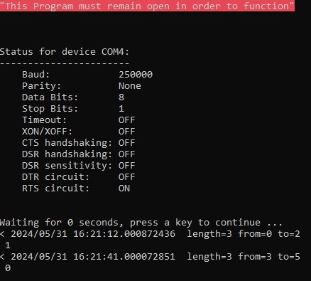
Hi all. I'm going to fine tuning for final testing (and hopefully start flying...) all my cockpit panels. As per title, I'm getting an issue with the Head-on airborne target button: the Bort snippet is DcsBios::Switch2Pos weaponsForwardHemiTargetBtn("WEAPONS_FORWARD_HEMI_TARGET_BTN", PIN); but testing the button (starting only Socat with no DCS running) I expect to see the msg after pressing and releasing: WEAPONS_FORWARD_HEMI_TARGET_BTN 1 WEAPONS_FORWARD_HEMI_TARGET_BTN 0 but I get instead only: 1 0 and no sign of life in the cockpit (the virtual button) if I run DCS an press the button. I checked even the DCSBIOS Ka-50.lua file, but (for my knowledges - very limited) I don't see any issue. And the button as a LED too... Any suggestion / solution? Thanks
-
Here again one more time. I'm reporting an "extended issue" (or I suppose it could be really extended). The last release of BORT owns a very interesting feature, the Address Constants; as I think them very useful, I decided to change all the arduino sketches where I use LEDs (there are a lot of lamps in the Ka-50......). So for an entire week (the freetime isn't so much) I updated alle the LED sketches by using the new address constants snippets. While compiling every updated sketch, I got always the same error msg "X was not declared in this scope" for every LED snippet. Checking the Address.h library, the issue is related to a "_AM" suffix in the BORT snippet with no correspondence in Address.h library. My first solution was to arbitrary delete alle the _AM suffixes in every snippet. When compiling I didn't get any error msg more, so I updated all the sketches this way. This morning I started to upload the new sketches to the boards. The first "lucky one" was the APU Control Panel lamps. The same arduino drives the Fuel Vlv Levers and the Brake lever. I realized that the panel stopped working: the levelers where dead, so as the LEDs. After several try and retry (and a burned arduino ....damn....) I checked the snippets and the Address.h again Something like: APU fuel shutoff valve is open Lamp (green) DcsBios::LED apuFuelVlvOpen(Ka_50_APU_FUEL_VLV_OPEN_AM, PIN); But in Address.h it should be: Ka_50_APU_FUEL_VLV_OPEN 0x191A, 0x1, 0 But beside the missing _AM suffix, even the values aren't matching. In fact, unticking the Use Address Constants box in BORT, the same LED has this snippet: DcsBios::LED apuFuelVlvOpen(0x191a, 0x0001, PIN); But these values don't match the Address.h library. I'm not a programmer (not at all....), but I think 0x1 is not seen in the same way as 0x0001 by a computer So, unticked the box, I used the other snippets, and everything started working fine now. I don't know if I wrote a lot of bulls**ts and there's no issue at all (it's just me an idiot) , but is the only solution I found for the problem. Nevertheless, the possibility to use a constants is very useful for the reasons they where implemented in DCSBIOS, so I'd like to use it someday. By now I think I'll reprogram all the sketches back to the old version.... @No1sonuk As I have a github account now, can you tell me where to report an issue there? and if you can be so kind to report this new one to for me now. Sorry if I ask again, but is there any solution the the previous message issue (the Head-on airborne target button)? Thanks all
-
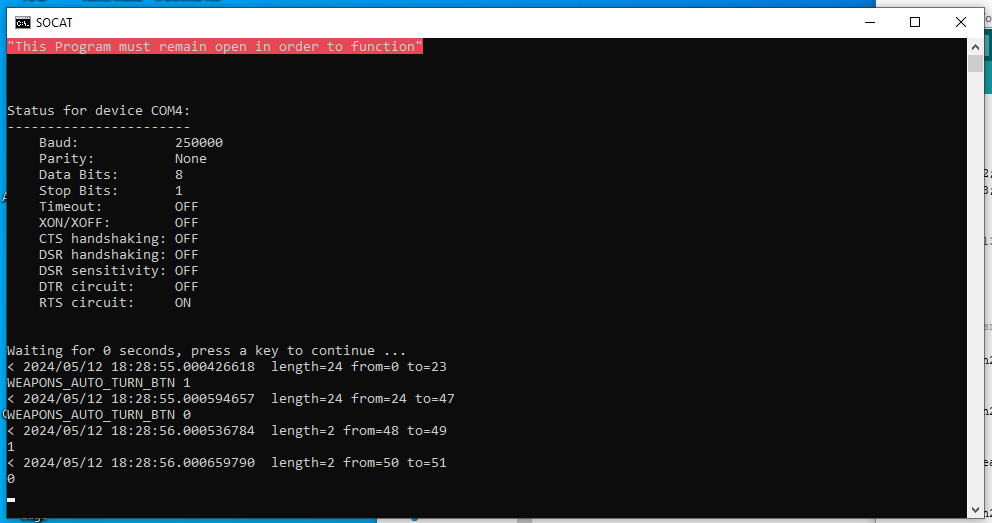
Here again with another issue. This time is Targeting Mode Control Panel. The problem is the Head-on airborne target button My snippet code is: //AUTOTURN BTN DcsBios::Switch2Pos weaponsAutoTurnBtn("WEAPONS_AUTO_TURN_BTN", AutoturnBtn); //A/A H O BTN DcsBios::Switch2Pos weaponsForwardHemiTargetBtn("WEAPONS_FORWARD_HEMI_TARGET_BTN", AAHBtn); But in the sim autoturn works properly, the second one gives no sign of life. In Socat I can see the commands as in picture, where you can see the first command given is related to Autoturn and the second to Head-on airborne target button In both cases the command is sent, but only the first get a response, not the second. Honestly the second message sent seems very weird to me, but this is what I'm getting (only 1 and 0, with no message.....).... Well I tried but when I compile I get a bounch of error related to the new Addresse.h, so I back the the last one....
-
DCSBIOS and BORT update and problem with the snippet (Ka-50 module)
Jocman replied to Jocman's topic in Home Cockpits
I think I fixed the 1st issue too. Instead of using a normal Multipositionswitch, I built a voltage divider and used the AnalogMultiPos The thing now works; or at least it seems working, but: - There's a short delay (ok, little less than 1 second) between the physical action and the simulated action. And I have only 2 boards at this testing time: the RS485Master and 1 slave; and on this slave there's only 1 snippet (the AnalogMultiPos) - Until I load and test just 1 snippet, beside the delay, everything works. - But I if I try to load and test both the snippets (on the same board), this is what happens: moving the switch, the one which I expect to move, is correctly moving; but even the second one moves..... For the sake of honesty, i say that i made only one voltage divider, switching it from A0 to A1 to test both snippets. I soldered 4 1k resistors, and a crocodile to connect the +5V to the 4th (3 resistors) or on the 5th (4 resistors) switch pin (depending if I'm testing a 4 or 5 steps Analog device) I dont'know if this behaviour it's because if I program 2 AnalogMultiPos, the system WANT to see 2 devices conneccted (and not only 1); but in case not, why this happens??? the 2 snippets: DcsBios::AnalogMultiPos radioSelector("RADIO_SELECTOR", A0, 4); DcsBios::AnalogMultiPos weaponsMode("WEAPONS_MODE", A1, 5); UPDATE I decided to build a second voltage divider, so to have one well configurated for both selector. Everything works fine, no issue at all. I learned another lesson: YES, THE BOARD EXPECTS 2 DEVICES IF YOU PROGRAM 2 DEVICES! Only one curiosity: why the multiposition switch doesn't work? I mean, the standard multiposition..... At this point it doesn't really matter, 'cause I think I'll switch to AnaloMultiPos for all the selectors of my cockpit (and save pins)...... Anyway, thanks all for your patience and support -
Uhmmmm, honestly when i got the issue, i downloaded all the new fork related releases from skunkworks (arduino library, dcsbios and bort). Right now i'm not home, but if i'm not wrong dcsbios is release 8 (or anyway the all-in-one or smtg like) and the library i'm sure is the last update. Same about bort. To be someway sure, i first deleted everything the reinstalled the updated versions. Then i got the issues i'm reporting
-
Hi all. I'd like to report a couple of errors I found in BoRT snippets while trying to display the R-800 VHF frequencies (Ka-50 BS3). I was keeping having the same error message on arduino IDE whe trying to read FrequencY1: "Ka_50_R800_FREQ1_A was not declared in this scope" After lot of try, I checked the library Addresses.h and found that the right string is not "Ka_50_R800_FREQ1_A" but "Ka_50_R800_FREQ1_ADDR" Same issue (and solution) for Frequency4: is not "Ka_50_R800_FREQ4_A" but "Ka_50_R800_FREQ4_ADDR"
-
DCSBIOS and BORT update and problem with the snippet (Ka-50 module)
Jocman replied to Jocman's topic in Home Cockpits
Thanks for your support Vinc_Vega. BTW, I fixed the 2nd issue too. I found an error in BoRT: when the IDE reports me the message "Ka_50_R800_FREQ1_A was not declared in this scope" it's due an error in the snippet, as (searching in Addresses.h library) is NOT Ka_50_R800_FREQ1_A but Ka_50_R800_FREQ1_ADDR (BoRT misses DDR) Same issue for frequency 4, where BoRT reports Ka_50_R800_FREQ4_A instead of Ka_50_R800_FREQ4_ADDR Now I can display correctly both VHF frequencies. Unfortunately, I started with an issue with the encoders: even if I fixed them for the click-jump, as I connected more arduinos (3 panels) to check with some "load", the frequencies are fine, but turning the encoders doesn't work in the right way, as it seems there's a huge delay between the click and the PC response (if I get response....) -
DCSBIOS and BORT update and problem with the snippet (Ka-50 module)
Jocman replied to Jocman's topic in Home Cockpits
Solution to 3rd issue (Encoder) Found the solution in an old ED Forum post, related to this link: https://github.com/DCS-Skunkworks/dcs-bios-arduino-library/wiki/RotaryEncoder Now it seems fixed and working. 1st and 2nd issues still remain.... I'm going on with some test, but can't fix them. Anyone has some idea? -
Hi all. I'm going on with testing my panels. Couple of days ago, I downloaded and updated to last version: DCSBIOS (program and arduino library) and BoRT. Actually, in my panels I still have the arduino coded with "old" version of DCSBIOS (at that time I was still using the Chrome reference). In particular, I'm testing the left consolle (radio, engines and weapons), but I'm getting some problem. FIRST ISSUE All the buttons and switches work fine (until now, hopefully...), but the SPU9 intercom selector and the Cannon mode selector don't ( I'm using rotary switches, they work fine for the APU ENGINE selector instead of a 4 way switch I don't have..))..... they don't give any sign of life. Both of them are connected to pin 13, 14, 15, 16 (I use arduino nano), of course 2 different nano, with these snippet: //RADIO SELECTOR const byte radioSelectorPins[4] = {13, A0, A1, A2}; DcsBios::SwitchMultiPos radioSelector("RADIO_SELECTOR", radioSelectorPins, 4); and on the second nano: //CANNON WEAPON SYSTEM SELECTOR const byte weaponsModePins[5] = {13, 14, 15, 16, 17}; DcsBios::SwitchMultiPos weaponsMode("WEAPONS_MODE", weaponsModePins, 5); As you can see, I tried with both pin notation (number or letter), but nothing to do. I tried with a brand new nano with only a rotary connected on pins 4, 5, 6, 7, but same issue: no life.... SECOND ISSUE As I'm using some 7 segment diplays with Max7219, I can't display the VHF frequencies. With the PVI800 (while doing some test time ago) everything worked fine, so I think the PCB is correctly working. But I noticed some differences (and having some error in compiling) with the new BoRT snippets. With the old reference, this was the snippet (i.e. for the frequency 1): void onR800Freq1RotChange(char* newValue) { /* your code here */ } DcsBios::IntegerBuffer r800Freq1RotBuffer(0x1910, 0x0ff0, 4, onR800Freq1RotChange); The new reference on BoRT is: void onR800Freq1Change(char* newValue) { /* your code here */ } DcsBios::StringBuffer<2> r800Freq1StrBuffer(Ka_50_R800_FREQ1_A, onR800Freq1Change); There are some differences, in the last line, where the old snippet reports (0x1910, 0x0ff0, 4, onR800Freq1RotChange) while the new one: (Ka_50_R800_FREQ1_A, onR800Freq1Change) when compiling with the new snippet, I get the error message: "Ka_50_R800_FREQ1_A was not declared in this scope" Compiling with the old one gives no error, but I can't read anything about the frequencies.... THIRD ISSUE Is a problem related to the encoder I use to select the frequency (and, generally speaking, I use the same type of encoder in all my panels.....). Turning back and forth, every click is not a single change in frequency, but 2 or even 3 jumps.... I'm afraid to get tha same behaviour for the other panels too. What's wrong? I know I wrote a lot about issues, but there are 4 days I'm dealing with that with no good results.... Thanks in advance for your help. Jocman
-
As I understood, the STM32 analog input are working but the resolution isn't the best, so using an external ADC fix the problem and gives a better resolution I'll have a search for discord. Anyway, reading the freejoy documentation it seems that (as in my previous post) the wiring could be as descripted. But before etching a PCB I'll try on discord channel (hoping to get into...)
-
Yep, you're right, this could be an easy and maybe more reliable solution, even thouh I've to read the doc, considering I made the slave boards (with the 74HC165 chains) and see how to wire them to the card. What can I say? DIY sickness? Anyway, as I already made the 2 slave PCBs and got the DAC, I'd like to try the quest. Keeping studing, maybe the solution to my question could be: - cyclic shift register chain CLK + collective shift register chain CLK + MCP3208 CLK > all to SPI SCK pin on STM32 - cyclic shift register chain DOut + collective shift register chain DOut + MCP3208 DOut > all to SPI MISO pin on STM32 - cyclic shift register chain Latch > to pin X on STM32 - collective shift register chain Latch > to pin Y on STM32 - MCP3208 Latch > to MCP3208 CS on STM32 Could this work?
-
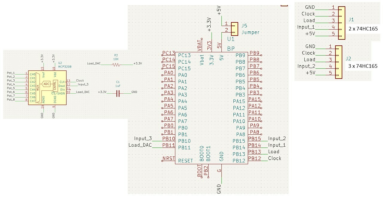
Hi all. As my home cockpit is getting on (my wife says she can see the light at the bottom of the tunnel, but I honestly not yet....), I' starting to work on the home made controls (cyclic, collective, rudder). Freejoy is my choice for the quest, so I started etching the PCBs. The cyclic is based on 2 shift register 75HC165 daisy chained, the collective on 3 shift register 75HC165 daisy chained: every PCB will host the shift registers.. As I will need 6 analog axis, I wish to ad an MCP3208 DAC. The PCBs for cyclic and collective are done, now I'm working on the main PCB (ST32 + MCP3208). Now my doubt: how to connect the MCP3208? The shift registers can share clock and load pins, the cyclic will have ad additional Input 1 pin, and the collective an additional Input 2 pin. As the MCP3208 owns a Clock and Load pins too, can these be shared with the 75HC165, or they need separate pins? As you can see, I planned to share the MCP3208 Clock pin with the 75HC165: is this correct? Attached a schematic related to second option (MCP3208 on separate pin). Your opinion and suggestion are obviously welcome. Thanks Jocman
-
Thinking to quit, but it deserves one more (or more...) chanche on RS485
Jocman replied to Jocman's topic in Home Cockpits
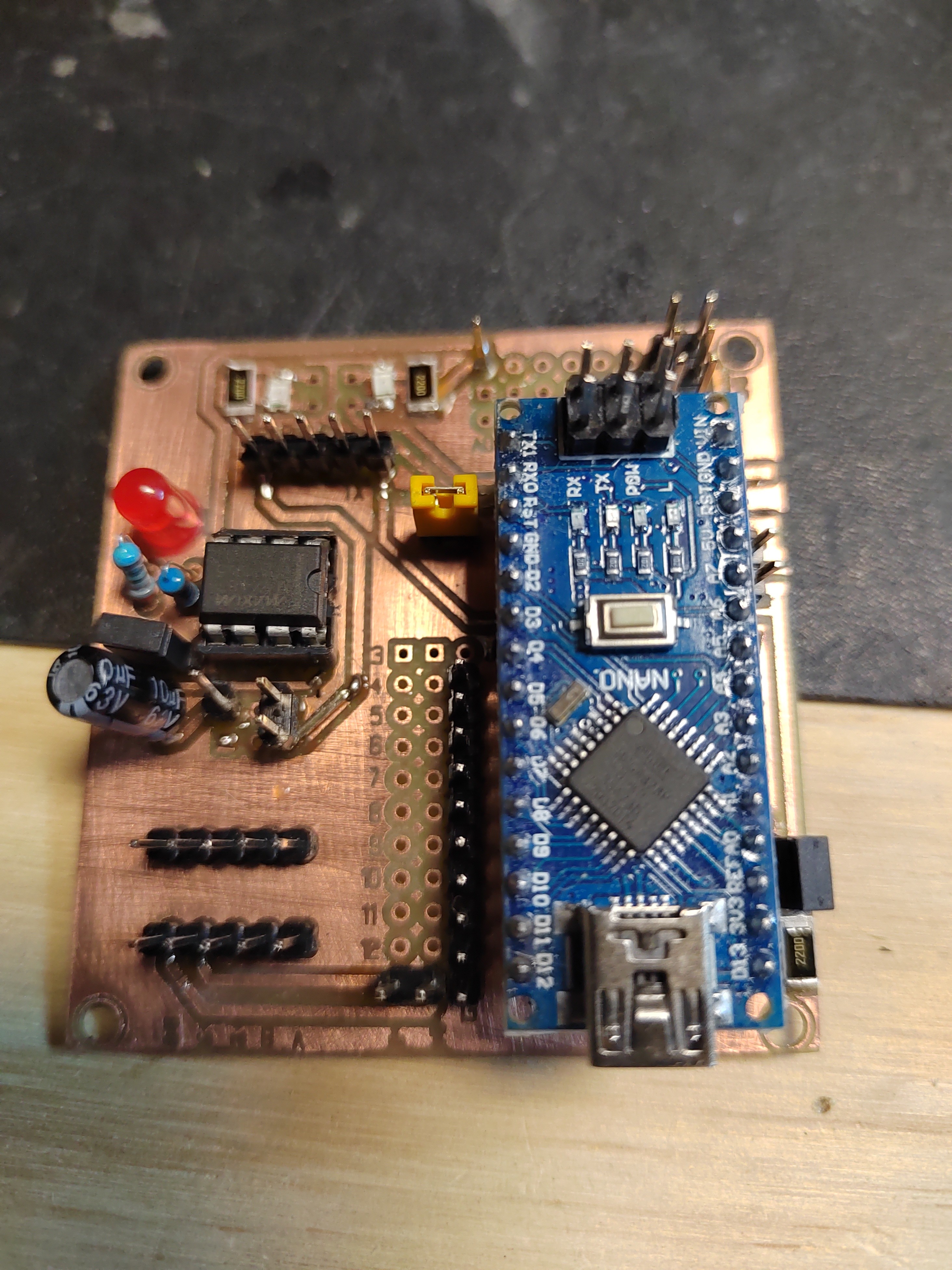
Slave proto made. Not all the components are present, but just to test if everything works. Btw, for the final version i'll change something: - Max487 feeded directly by arduino's +5V (keeping the possibility to select if feed arduino by 12 or 5V) - same thing for the 2 led Tx/Rx - added 2 leds to indicate the presence of 5V and 12V Next step, a new master pcb (but i'm waiting for the components from China) and a RS485 hub
-
Thinking to quit, but it deserves one more (or more...) chanche on RS485
Jocman replied to Jocman's topic in Home Cockpits
Thanks for your sharing, Vinc. Here's my possible new version of PCB (i use kicad). Is intended to be used with Nano (onboard) or,alternatively, Mega (wired). More, there is a rs485 through (from blue73 design). Possibility to feed Nano with 12 or 5 V (using a jumper) Jumper to power on/off the Max847 Jumper to enter in "onboard program mode" (i read on italian forum you need just to break the wiring RO→Rx to do it - hope is right). Btw,is it not enough to unpower the Max487? Max487 power led rx/tx led (with plugs to wire external led) 12V rail 5V rails Now I should make a prototype and test it. and someway fix my doubt on shielded/twisted wires (well, the distances could be important)....
-
Thinking to quit, but it deserves one more (or more...) chanche on RS485
Jocman replied to Jocman's topic in Home Cockpits
Not sure to understand (sorry, my poor english); currently I'm not feeding anything from the arduino 5V out. All 5V to the various stuff are provided by the PSU (5V 30A), wich, currently, feed arduino too via 5V pin. so Arduino is not overloaded with current In my plans for new PCB design, I'll use the 12V to feed Arduino via Vin pin, thus the 5V pin will be not connected to anything else. Aside this, anything about the need / not need to use twisted/shielded/both wires for AB signal?