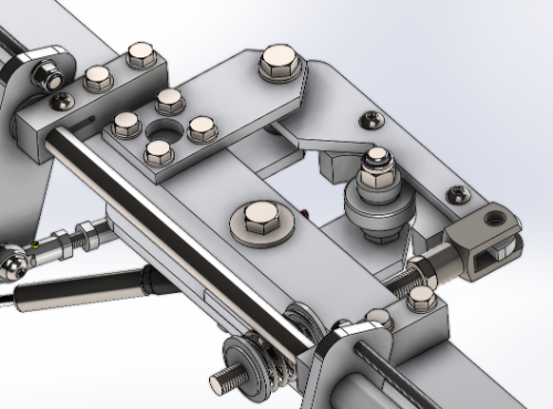
edmuss Posted October 10, 2023 Posted October 10, 2023 Following on from this: - https://forum.dcs.world/topic/319474-diy-mechanical-cyclic-trimmer/ Whilst the last iteration worked nicely as a trim mechanism, the range of movement of the stick whilst trimmed was only a couple of inches which wasn't really enough - it should be full range of motion but sprung. Inspired by the stupendous mi24p simpit by @molevitch, who fortunately assisted on the bits I'm too thick to work out myself Also inspired by the cyclic mechanism made by @yoreh, which I originally saw linked to by @bradmick in discord. I set about designing an electromagnetically locked trim mechanism with the intention that it would be mostly 3D printed where practical and be a bolt on to a stock warthog stick/base with minimum of modifications. I intended to reuse the trim lever, gooseneck extension from the mechanical trim. I sourced a bunch of cheap 300kgf security door maglocks on ebay with the intention of using one to lock the axes when force trim is released, I also wanted to eliminate as much slop in the mechanism as possible so opted for linear bearings for the spring units, oilite bushes for the spring rods, rod end bearings for the linkages and ballraces for the bellcranks needed to translate the motion. Threw all the bits togther in solidworks and after a few weeks of thought and design iteration this is the result! null The maglock is mounted behind the stick base, spring units and linear bearings on a 50x8 aluminium strap to resist the forces to be applied. The bell cranks are mounted onto the triad ring (reused from the mechanical system) clamped to the top of the stick base, each crank has a pair of ballraces to keep everthing smooth and tight. The original printed bell crank supports weren't stiff enough so I cut the half moon braces from the same 50x8 aluminium, the lower is bolted through the base plate (the only modification I've had to make to the stick base) and M8 all-thread tapped and locked into position. The original springs (shown) didn't have a high enough rate to resist the weight of the heavy grip sagging when not centralised so they have been replaced with some much heavier units which work well enough. The springs have adjustable preload by winding in the knobs at the back - in reality I have these wound in fully so largely pointless now but they aid assembly. The through rod on the spring units are running on the oilite bushes so as to not bind at all. The original armature plate for the maglock was obviously not suitable so I cut some 5mm mild steel plate at work and spent a couple of hours draw filing to ensure that they were as flat and smooth as possible. Air gap is the enemy of electromagnets so it was essential that these were flat enough to attract with enough force. The maglock needs to be energised when the force trim control is inactive and de-energise when holding the force trim, I had previsouly used a tact switch wired into a cheap USB controller board for the mechanical trim and it worked very well. The maglock needs a 12v supply so obviously power needs to come from somewhere else, additionally the normally open tact switch wouldn't be suitable for switching the maglock whilst still connected to the USB board. I used a 5v relay (the blue and red thing) set to normally closed operation to keep the maglock energised until the tact switch is depressed; this also required a 5v feed in addition to the 12v. I sacrificed a power cable for my PSU to supply both 12v and 5v using, extended and braided the cable into a loom to so the stick is constantly plugged into the computer PSU - peak current draw is about 6w at worst and almost zero once the maglock is energised. The physical manifestation! Video evidence! https://photos.app.goo.gl/86ew3K5fVxanxFrf6 https://photos.app.goo.gl/eXPQEFSnvz1uyw3R6 https://photos.app.goo.gl/Rtuwt5BKyfoG5cvf6 https://photos.app.goo.gl/HNatykyBPiv4YQFe7 I had to tweak the balance point of the gooseneck to stop some sagging on the pitch axis in certain trimmed positions (damn that heavy metal grip!) but it's all good now. The total weight of the joystick is now around 6.3kg. I also replaced the original warthog gimbal with this as the stick is over 10 years old and had developed a bit of rotational movement which would only be exacerbated by the offset spring loads applied by the linkages. The switch to a full ball race gimbal is nice although I did need to reinforce the prints with some 1.8mm stainless rod to keep the strength in them. I retained the original warthog spring to apply a slight passive centring force so that it's easy to refind centre if need be - the length of the extension means it can be overcome by the weight of the grip alone. In use the stick behaves exactly as I intended, pulling the trim lever de-energises the maglock and it becomes light as a feather, essentially a floppy dead stick, releasing the trim energises it and locks it into position. Whilst trimmed there is a fairly soft return to the trim centre so the stick doesn't significantly osscilate but it's enough to give a definite force so you know you're flying against the trim. Very pleased with the result, it's become something of a monster project and has become a little more involved tooling wise (beyond the 3D printer) than I'd like but it's doing exactly what I set out to do. If flying fixed wing then I just leave the trim lever alone and the stick behaves like a normal sprung centre joystick. If anyone is masochistic enough to want to make one, I can let you have the STLs for printing and generate a set of drawings for the other parts to be made - it's obviously designed around my specific gooseneck but it should be pretty simple to redesign the linkage base to suit a stock warthog or extension. Why? Because I like to tinker, does it make me a better pilot? Absolutely not but it's fun to use! 2 2 Ryzen7 7800X3D / RTX3080ti / 64GB DDR5 4800 / Varjo Aero / Leap Motion / Kinect Headtracking TM 28" Warthog Deltasim Hotas / DIY Pendular Rudders / DIY Cyclic Maglock Trimmer / DIY Abris / TM TX 599 evo wheel / TM T3PA pro / DIY 7+1+Sequential Shifter / DIY Handbrake / Cobra Clubman Seat Shoehorned into a 43" x 43" cupboard.
CrashMeTwice Posted October 10, 2023 Posted October 10, 2023 1 hour ago, edmuss said: Following on from this.... Wow, you have certainly put a lot of thought and work into it. Awesome job! 1
corbu1 Posted October 10, 2023 Posted October 10, 2023 That is so awesome!!! 1 DCS Version: 2.9.19.13478 Modules: UH-1H - SA342 - KA-50 BS3 - MI-24P - MI-8MTV2 - AH-64D - CH-47F - OH-58D - UH-60L(Mod, n.i.) - OH-6A(Mod, n.i.) - A-10CII - F-16C - F/A-18C - AJS37 - F-14 - MiG-21bis - JF-17 - Mirage F1 - MiG-29A (prepurchase) - C-130J (prepurchase) - FC2024 -Combined Arms - Supercarrier - NTTR - Normandy2.0 - Channel - Persian Gulf - Syria - SA - Sinai - Afghanistan - Kola - Iraq - Cold War Germany — Waiting for: BO-105 - AH-1G/F(Mod) DCS-Client: 9800X3D, 64GB 6200, RTX3090, 1TB M2 NVMe(win10), 4TB M2 NVMe(DCS), VR VivePro2, PointCTRL, VaicomPro, Wacom Intuos S with VRK v2Beta DCS-DServer: 11600KF, 64GB 3600, GTX1080, 1TB M2 NVMe(win10), 2TB M2 NVMe(DCSDServer), DCS Olympus Simpit: NLR Flightsim Pro Cyclic: TM Warthog Grip with 30cm Extension + VPforce Rhino FFB FW Stick: TM Warthog Grip and Base, Throttle: TM Warthog Pedals: Komodo Sim. with Dampers Collective: VPC Rotorplus+AH-64D Grip Other: NLR HF8, Buttkicker (3*MiniConcert), TotalControls AH64D MPD‘s and EUFD, Alain Dufour’s AH-64 TEDAC, TM MFD, Streamdecks (1*32,3*15,1*6), VPC CP#1
markturner1960 Posted October 14, 2023 Posted October 14, 2023 Wow Edmuss, that is seriously impressive! System specs: PC1 :Scan 3XS Ryzen 5900X, 64GB Corsair veng DDR4 3600, EVGA GTX 3090 Win 10, Quest Pro, Samsung Odyssey G9 Neo monitor.
Recommended Posts