Rapti
-
Posts
163 -
Joined
-
Last visited
Content Type
Profiles
Forums
Events
Everything posted by Rapti
-
no they are 8in Aliexpress HDMI diplays for 30$ each https://de.aliexpress.com/item/4000255841162.html?spm=a2g0s.9042311.0.0.6ef24c4dR5936F
-
New case in the making Gesendet von meinem SM-G988B mit Tapatalk
-
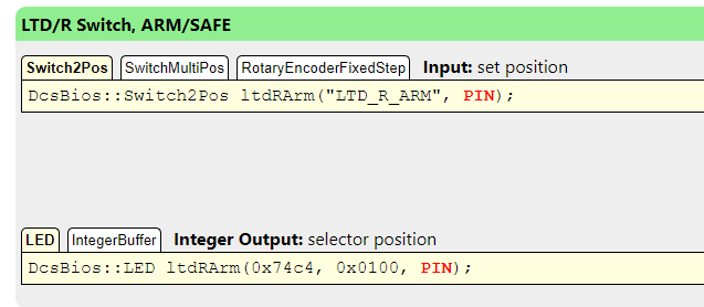
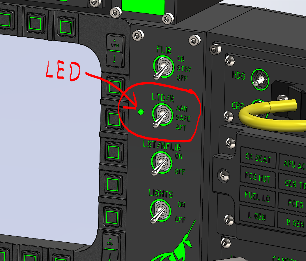
I would like to display the status of the LTD/R switch via a flashing LED. In reality the LTD/R switch is a magnetic switch. I would use a normal switch instead of the magnetic switch, which does not remain in the on position, but goes back to the off position by a spring. (momentary switch) To see at a glance if the laser is "armed" I would like to show the armed state with a blinking LED. For this purpose there is the following line in the Control Reference in DCS BIOS: DcsBios::LED ltdRArm(0x74c4, 0x0100, PIN); this works as far as possible. How do I get this LED blinking?. How do I get that in the Arduino Sketch? Can someone help me?

-
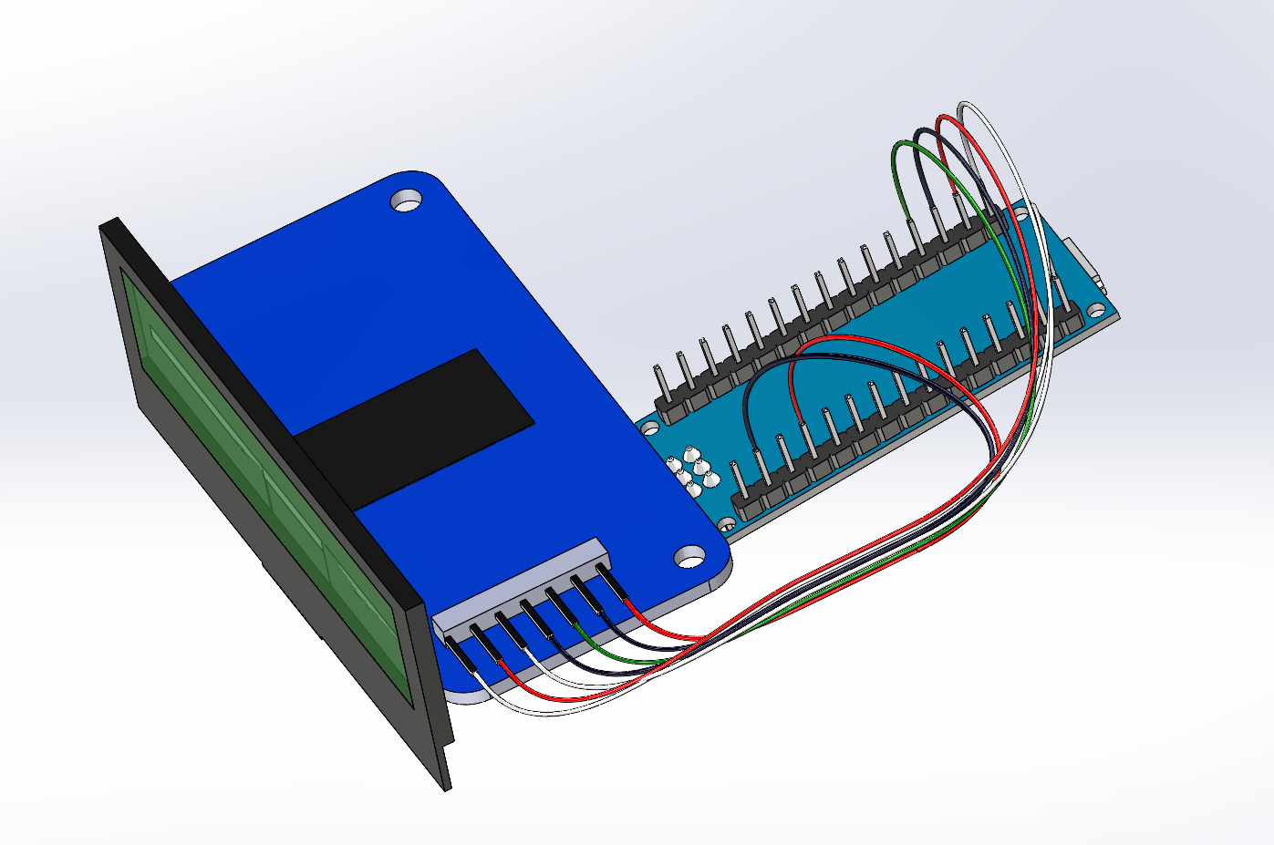
I used these displays: https://www.waveshare.com/2.23inch-oled-hat.htm I separated the PCB from the display- it is connected with doublesided tape. Each one is connected as a standard SPI display to a separate arduino nano.
-
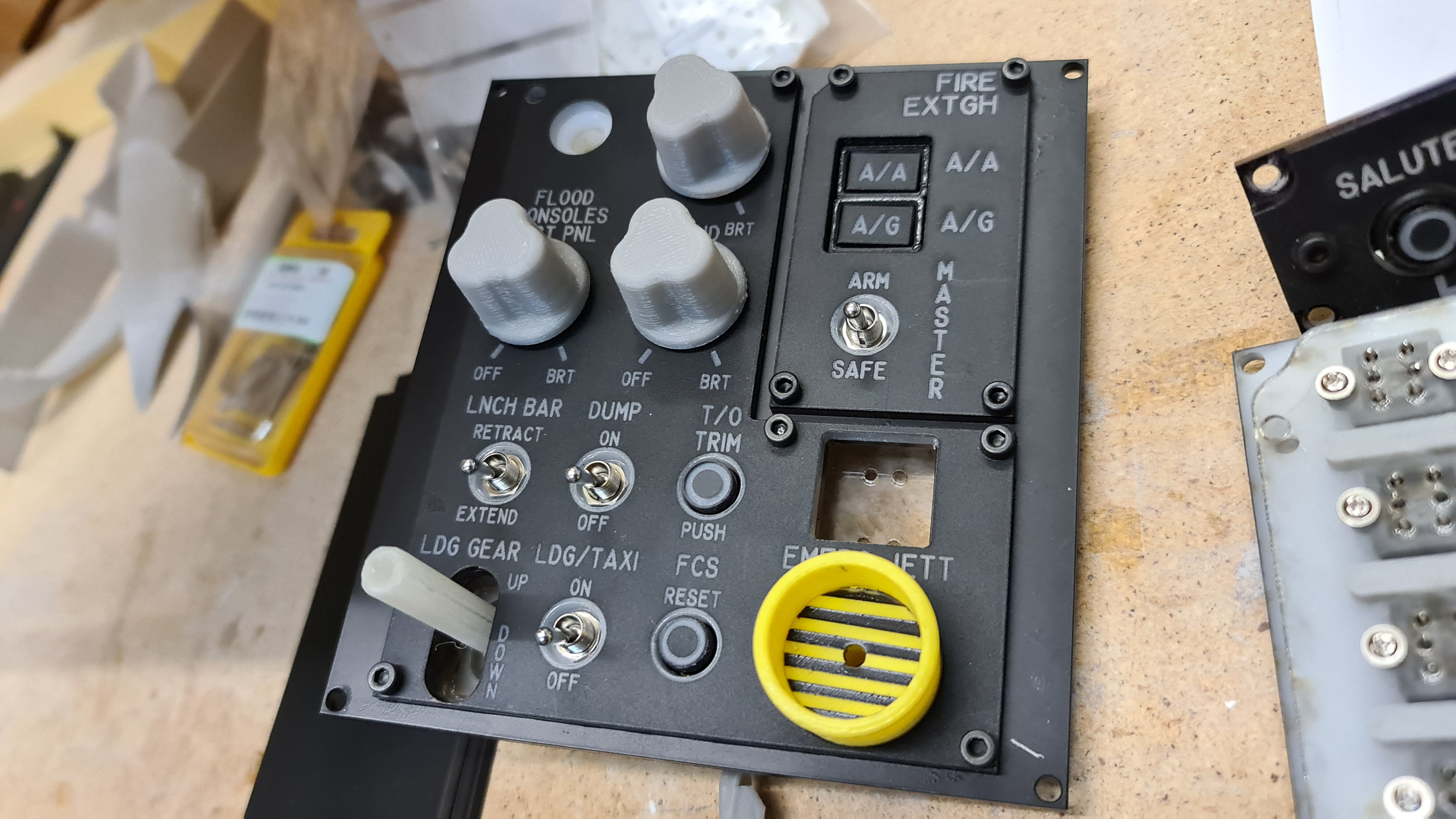
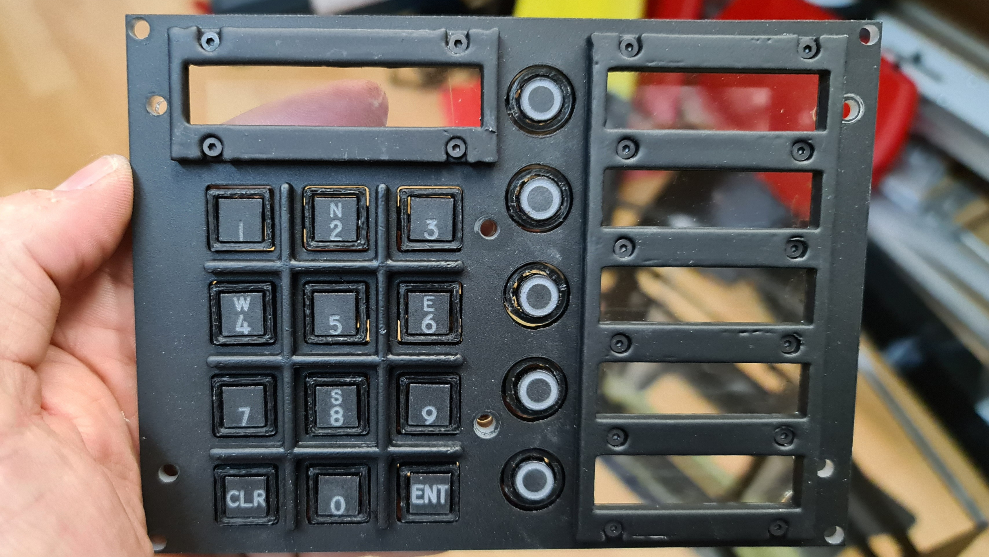
I redesigned the button box to fit a new UFC with functional displays. I move the DDI's next to the UFC. Gesendet von meinem SM-G988B mit Tapatalk
-
Hi, I saw your Arduino code here and am trying to get my OLED's from the F/A-18 UFC to work with it. Actually I don't have much idea about Ardunio. With the help of your sketch I got the scratchpad working. I deleted everything except the lines for the scratchpad and ran the loops only 1 time. Das funktioniert soweit: https://www.facebook.com/1557214885/videos/10224354526881584/ What does not work is the control of the options displays. If I take your code directly, this is what happens when I make an input on the UFC. All displays are shown one after the other in the OLED display and that about 3 times in a row. What should the code look like if I want to use one Arduino Nano per Options Display? Can you help me with this? I would be super grateful for it. Greetings Ivor
-
Will add both DDI's Gesendet von meinem SM-G988B mit Tapatalk
-
 Where is the popcorn?
 -
Displays will come later Gesendet von meinem SM-G988B mit Tapatalk
-
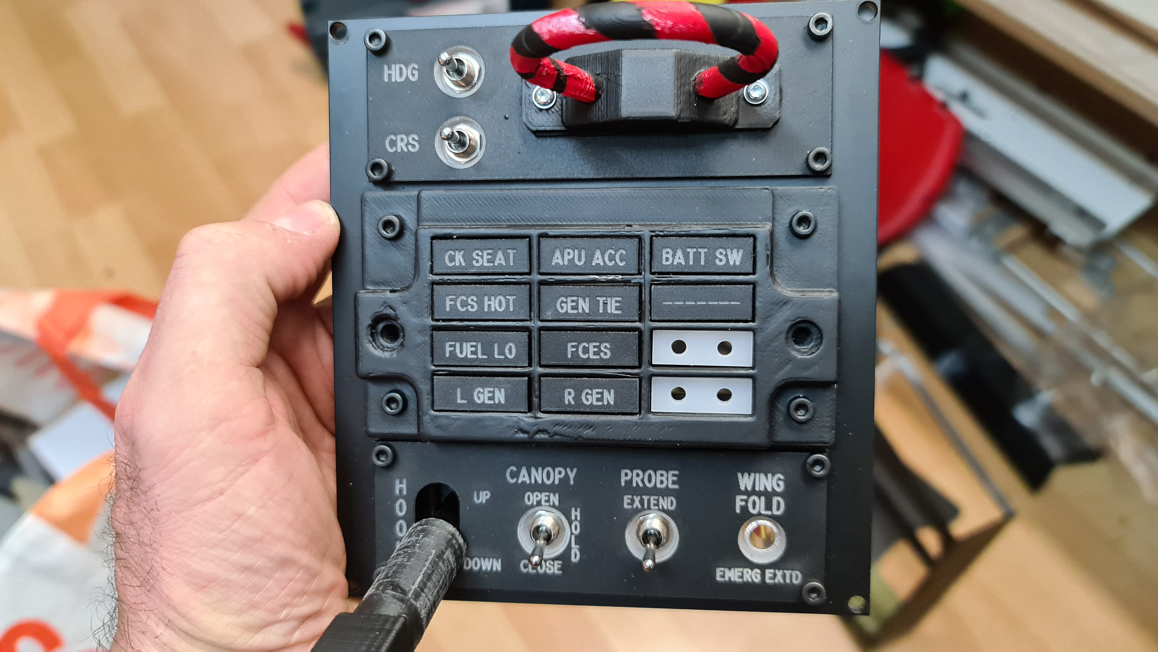
Almost done Gesendet von meinem SM-G988B mit Tapatalk
-
Progress Gesendet von meinem SM-G988B mit Tapatalk
-
In my opinion the hardware recommendations from EA are far from sufficient. I have recently built a new PC. ASUS Maximus XII Hero motherboard Intel I9-10909K MSI RTX3800 NZXT Z73 aio water cooling 64GB RAM 2TB m.2 SSD 850W ASUS ROG Thor power supply This is enough to fly with highest settings in DCS with 50 - 100 FPS. And this in singleplayer well understood. Gesendet von meinem SM-G988B mit Tapatalk
-
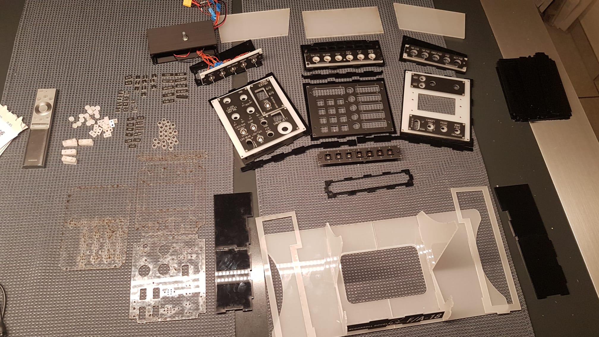
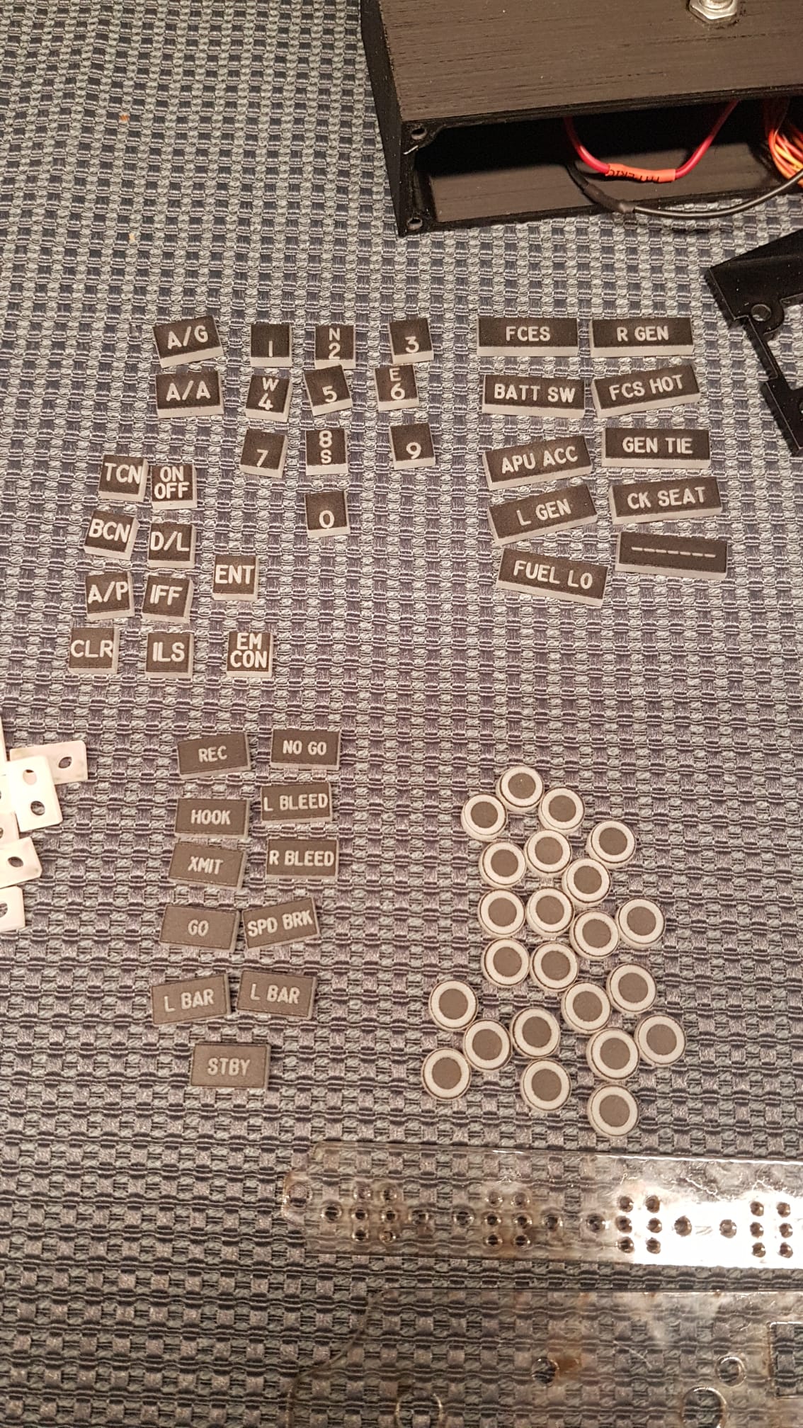
Some New pictures... Gesendet von meinem SM-G988B mit Tapatalk
-
Openhornet.com There are solidworks files
-
Hi Hans, When the RS485 network did not work, I first tested the individual components. Therefore I tested the NANO and the MEGA board separately. I noticed that the same circuit and the same code does not work with the MEGA board. When I used a PullUp resistor this board worked. The Post#5 referred to this separate test. i just checked the sketch. There is the end bracket. Probably it got lost when copying here in the forum.
-
so, the first problem is solved. On the MEGA board I definitely need a PullUp resistor on the Push Button.
-
you are right with 7V for the Nano. I know the thread from Hans - thanks. But why are the Mega's not able go communicate with DCS BIOS? I thinkna have to solve this Problem first. Any idea?
-
So 1. mistake... Max487 need 12V supply. But the problems starts earlier. When i try just the boards to communicate with DCS BIOS. Just the Arduino UNO and Arduino Nano can communicate with DCS BIOS. I have two MEGA boards. They dont work. I Can upload the Sketch. But nothing happen when connect to DCS BIOS. Any idea?
-
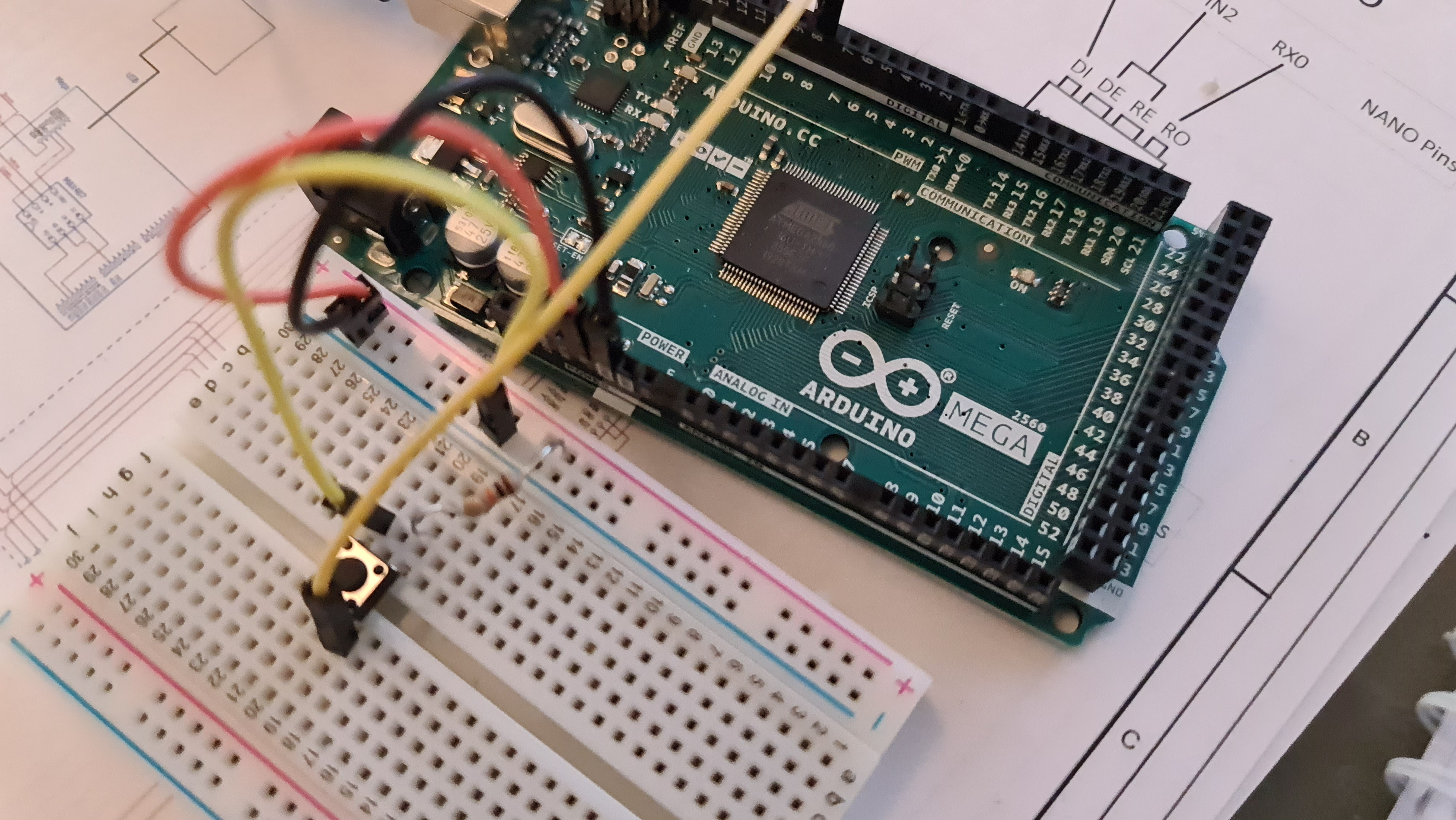
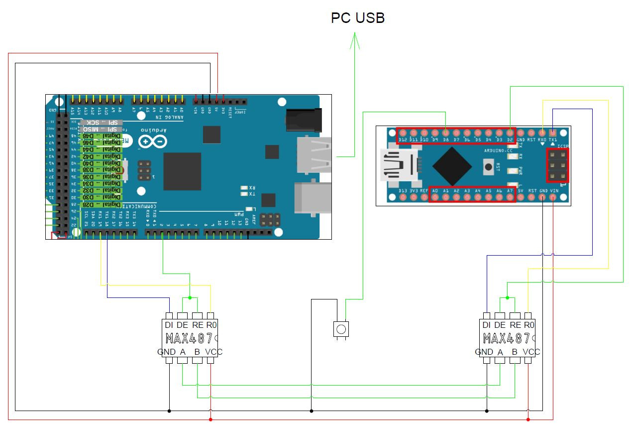
Hello everyone, i'm trying a first test to communicate with an Arduino Mega and an Arduino Nano via MAX487 chip. Unfortunately I can't get it there at the moment. I want to control the MasterCausion button and the MasterCaution LED as a test. have built the following circuit: --> see attached picture. I On the Adruino Mega I have uploaded the following sketch: /* Tell DCS-BIOS this is a RS-485 Master. You will need to flash this to a Mega 2560. */ #define DCSBIOS_RS485_MASTER /* Define where the TX_ENABLE signals are connected. You can connect up to three half-duplex RS-485 transceivers. Arduino Pin RS-485 Transceiver Pin TXn ------------------- DI (driver input) RXn ------------------- RO (Receiver Output) UARTn_TXENABLE_PIN ---- /RE, DE (active low receiver enable, driver enable) If you have less than three transceivers connected, comment out the corresponding #define UARTn_TEXENABLE_PIN lines for receivers that are not present. */ #define UART1_TXENABLE_PIN 2 //#define UART2_TXENABLE_PIN 3 //#define UART3_TXENABLE_PIN 4 #include "DcsBios.h" void setup() { DcsBios::setup(); } void loop() { DcsBios::loop(); } On the Arduino Nano I have uploaded the following sketch: /* The following #define tells DCS-BIOS that this is a RS-485 slave device. It also sets the address of this slave device. The slave address should be between 1 and 126 and must be unique among all devices on the same bus. */ #define DCSBIOS_RS485_SLAVE 126 /* The Arduino pin that is connected to the /RE and DE pins on the RS-485 transceiver. */ #define TXENABLE_PIN 2 #include "DcsBios.h" /* paste code snippets from the reference documentation here */ DcsBios::Switch2Pos masterCautionResetSw("MASTER_CAUTION_RESET_SW", 8; DcsBios::LED masterCautionLt(0x7408, 0x0200, 13); void setup() { DcsBios::setup(); } void loop() { DcsBios::loop(); } the whole thing does not work. As soon as I connect the COM port in DCS-BIOS the RX LED on the Arduino Mega flashes very fast. The LED on the Nano does not turn on when the MasterCaution LED in DCS is on. When I press the PushButton in the circuit, nothing happens in DCS. DCS-BIOS communicates with DCS without problems. Does anyone have a tip for me?
-
Yes when its finished Gesendet von meinem SM-G988B mit Tapatalk
-
Progress... Gesendet von meinem SM-G988B mit Tapatalk
-
Yes it's definitely not connecting. Did you try another USB Port? Gesendet von meinem SM-G930F mit Tapatalk
-
Laser was busy...