Rapti
-
Posts
163 -
Joined
-
Last visited
Content Type
Profiles
Forums
Events
Everything posted by Rapti
-
We use this display. Don't know if its the same than yours. IIC / I2C 2002 20x02 OLED Module Display Our Code: this work on our side. #define DCSBIOS_DEFAULT_SERIAL #include "DcsBios.h" #include "Wire.h" #include "OLedI2C.h" OLedI2C LCD; /* paste code snippets from the reference documentation here */ void onCmsp1Change(char* newValue) { LCD.sendString(newValue, 0, 0); } DcsBios::StringBuffer<19> cmsp1Buffer(0x1000, onCmsp1Change); void onCmsp2Change(char* newValue) { LCD.sendString(newValue, 0, 1); } DcsBios::StringBuffer<19> cmsp2Buffer(0x1014, onCmsp2Change); void setup() { DcsBios::setup(); Wire.begin(); LCD.init(); } void loop() { DcsBios::loop(); }
-
https://www.aero-news.net/index.cfm?do=main.textpost&id=0f5168ee-6721-40de-abee-e03759c96dc7 Gesendet von meinem SM-S928B mit Tapatalk
-

Exportable HMCS/HMD Viewport for A-10C II (and other modules)
Rapti replied to Raptikiller's topic in Wishlist
+1 – This feature is absolutely essential for many users I fully support this request and want to emphasize how important this functionality would be for a large part of the DCS community. For cockpit builders who use multi-screen or projection setups instead of VR, the current HMCS/HMD implementation is often unusable. The symbology becomes difficult or impossible to see because it’s fixed in space rather than following the head’s position as it would in a real helmet-mounted display. The fact that MFCDs and other displays can already be exported proves that viewports are supported and feasible. HMCS/HMD should be no exception. A head-tracked, exportable HMCS viewport would be a game-changer for non-VR cockpit setups. Please consider this seriously — many advanced users would greatly benefit from it. Eagle Dynamics, I love your simulator. Keep on going the good work!!! -
the stepper motor is an x27-168 The driver is a SparkFun EasyDriver Its controlled by a arduino nano Its the same setup then the setup from the warthog project.
-
Unfortunately, changing the value did not help. If anyone has a working sketch, I would be happy, as I unfortunately have no programming skills myself
-
I try that. Thanks for the tip. Gesendet von meinem SM-S928B mit Tapatalk
-
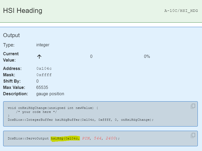
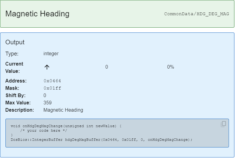
Hello everyone, I am trying to build the Standby Compass for my F/A-18 pit. For the A-10 I have successfully put it into operation with an Arduino sketch available on github: #define DCSBIOS_IRQ_SERIAL #include <AccelStepper.h> #include "DcsBios.h" struct StepperConfig { unsigned int maxSteps; unsigned int acceleration; unsigned int maxSpeed; }; class Vid60Stepper : public DcsBios::Int16Buffer { private: AccelStepper& stepper; StepperConfig& stepperConfig; inline bool zeroDetected() { return digitalRead(irDetectorPin) == 1; } unsigned int (*map_function)(unsigned int); unsigned char initState; long currentStepperPosition; long lastAccelStepperPosition; unsigned char irDetectorPin; long zeroOffset; bool movingForward; bool lastZeroDetectState; long normalizeStepperPosition(long pos) { if (pos < 0) return pos + stepperConfig.maxSteps; if (pos >= stepperConfig.maxSteps) return pos - stepperConfig.maxSteps; return pos; } void updateCurrentStepperPosition() { // adjust currentStepperPosition to include the distance our stepper motor // was moved since we last updated it long movementSinceLastUpdate = stepper.currentPosition() - lastAccelStepperPosition; currentStepperPosition = normalizeStepperPosition(currentStepperPosition + movementSinceLastUpdate); lastAccelStepperPosition = stepper.currentPosition(); } public: Vid60Stepper(unsigned int address, AccelStepper& stepper, StepperConfig& stepperConfig, unsigned char irDetectorPin, long zeroOffset, unsigned int (*map_function)(unsigned int)): Int16Buffer(address), stepper(stepper), stepperConfig(stepperConfig), irDetectorPin(irDetectorPin), zeroOffset(zeroOffset), map_function(map_function), initState(0), currentStepperPosition(0), lastAccelStepperPosition(0) { } virtual void loop() { if (initState == 0) { // not initialized yet pinMode(irDetectorPin, INPUT); stepper.setMaxSpeed(stepperConfig.maxSpeed); stepper.setSpeed(1200); initState = 1; } if (initState == 1) { // move off zero if already there so we always get movement on reset // (to verify that the stepper is working) if (zeroDetected()) { stepper.runSpeed(); } else { initState = 2; } } if (initState == 2) { // zeroing if (!zeroDetected()) { stepper.runSpeed(); } else { stepper.setAcceleration(stepperConfig.acceleration); stepper.runToNewPosition(stepper.currentPosition() + zeroOffset); // tell the AccelStepper library that we are at position zero stepper.setCurrentPosition(0); lastAccelStepperPosition = 0; // set stepper acceleration in steps per second per second // (default is zero) stepper.setAcceleration(stepperConfig.acceleration); lastZeroDetectState = true; initState = 3; } } if (initState == 3) { // running normally // recalibrate when passing through zero position bool currentZeroDetectState = zeroDetected(); if (!lastZeroDetectState && currentZeroDetectState && movingForward) { // we have moved from left to right into the 'zero detect window' // and are now at position 0 lastAccelStepperPosition = stepper.currentPosition(); currentStepperPosition = normalizeStepperPosition(zeroOffset); } else if (lastZeroDetectState && !currentZeroDetectState && !movingForward) { // we have moved from right to left out of the 'zero detect window' // and are now at position (maxSteps-1) lastAccelStepperPosition = stepper.currentPosition(); currentStepperPosition = normalizeStepperPosition(stepperConfig.maxSteps + zeroOffset); } lastZeroDetectState = currentZeroDetectState; if (hasUpdatedData()) { // convert data from DCS to a target position expressed as a number of steps long targetPosition = (long)map_function(getData()); updateCurrentStepperPosition(); long delta = targetPosition - currentStepperPosition; // if we would move more than 180 degree counterclockwise, move clockwise instead if (delta < -((long)(stepperConfig.maxSteps/2))) delta += stepperConfig.maxSteps; // if we would move more than 180 degree clockwise, move counterclockwise instead if (delta > (stepperConfig.maxSteps/2)) delta -= (long)stepperConfig.maxSteps; movingForward = (delta >= 0); // tell AccelStepper to move relative to the current position stepper.move(delta); } stepper.run(); } } }; /* modify below this line */ /* define stepper parameters multiple Vid60Stepper instances can share the same StepperConfig object */ struct StepperConfig stepperConfig = { 6000, // maxSteps 2000, // maxSpeed 1000 // acceleration }; // define AccelStepper instance AccelStepper stepper(AccelStepper::DRIVER, 5, 6); // define Vid60Stepper class that uses the AccelStepper instance defined in the line above // v-- arbitrary name Vid60Stepper hsiHdg(0x104c, // address of stepper data stepper, // name of AccelStepper instance stepperConfig, // StepperConfig struct instance 4, // IR Detector Pin (must be HIGH in zero position) 0, // zero offset [](unsigned int newValue) -> unsigned int { /* this function needs to map newValue to the correct number of steps */ return map(newValue, 0, 65535, 0, stepperConfig.maxSteps-1); }); void setup() { DcsBios::setup(); } void loop() { DcsBios::loop(); } This uses the “heading” value of the HSI as input for the standby compass: hsiHdg(0x104c). However, the F/A-18 does not have an HSI for which the heading value can be used. However, there is the “Magnetic Heading” under CommonData, which is output for each aircraft. But I don't know what to enter in the Arduino code. I tried it with the following value: HdgDegMag(0x0464) But it does not work. Does anyone know what needs to be entered?null A-10 Heading: Common Data Heading:

-
looks amazing! Did you make the wooden parts yourself? On a CNC?
-
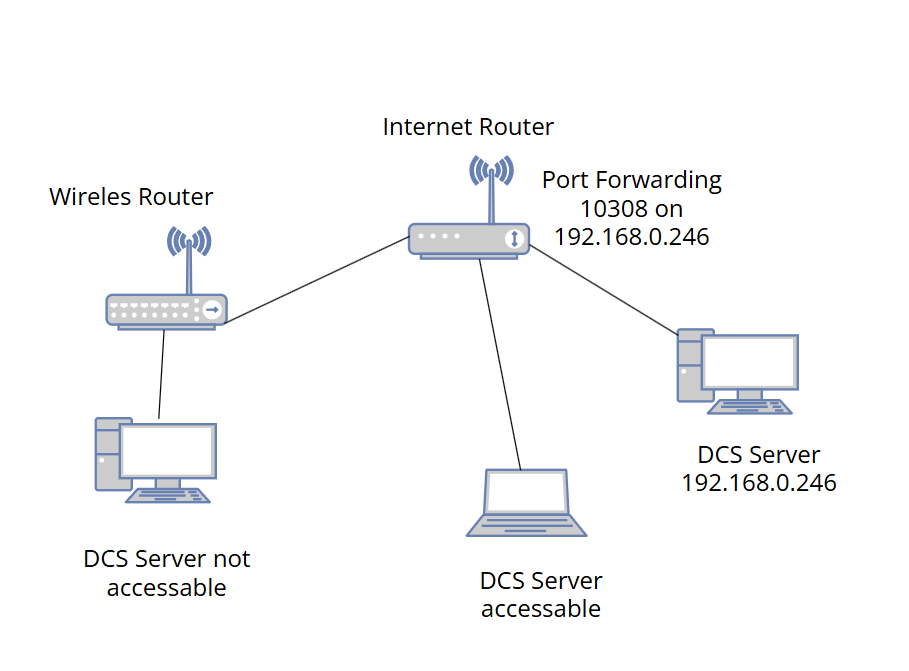
So, the Problem was the WiFi router. It creates a different subnet. I reconfigured the WiFi router to an Access Point. This was the solution. Gesendet von meinem SM-S928B mit Tapatalk
-
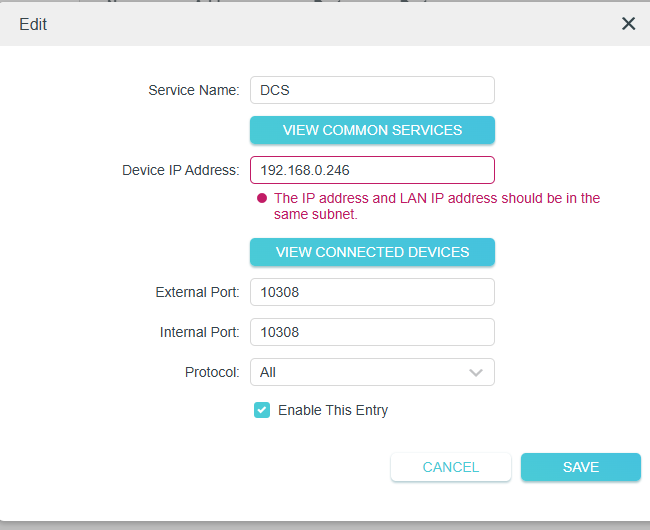
I'm getting a little closer. I have attached a wireless router to the Internet router, as I connect to the PC with a Quest 3 via Virtual Desktop. So the PC is connected to the wireless router via LAN cable and the wireless router is connected to the Internet router via LAN. I have tried to open port 10308 of the DCS server on the wireless router, as I did with the Internet router. However, the wireless router does not allow this. The wireless router only “sees” my PC and not the DCS server. Although I can ping the DCS server from the PC. From the PC, I am able to ping the DCS-Server Any advice?
-
So I tried another client computer. I can see my server there. So must something with the other pc.
-
hmmm dont work on my side... null
-
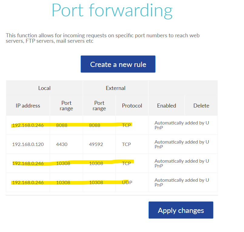
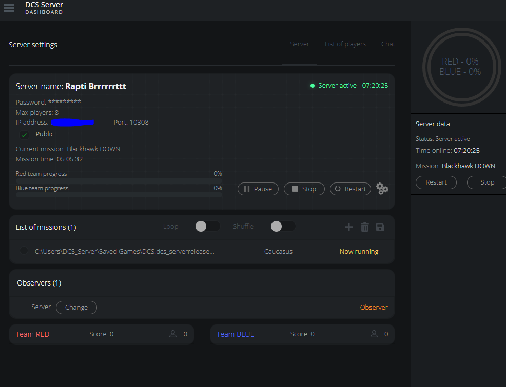
I installed a dedicated multiplayer server. Server is up and running. Port 10308 (TCP and UDB is forwarded) I still cant see the server in DCS World. What could be the cause?
-
This would be sooooo great! Gesendet von meinem SM-S928B mit Tapatalk
-
After building a A-10 pit with a friend, I started a F-18 pit. The A-10 pit is much more complicated interms of the panels. But the cockpit structure is complex in the F-18. I think both planes are cool. Gesendet von meinem SM-S928B mit Tapatalk
-
I would create one panel after another. It always motivated me, when I saw the result of a running panel. But it is a long journey. Keep on going. Keep posting your results. Below the first photo and the last on my phone of my pit. 2.5 years between
-
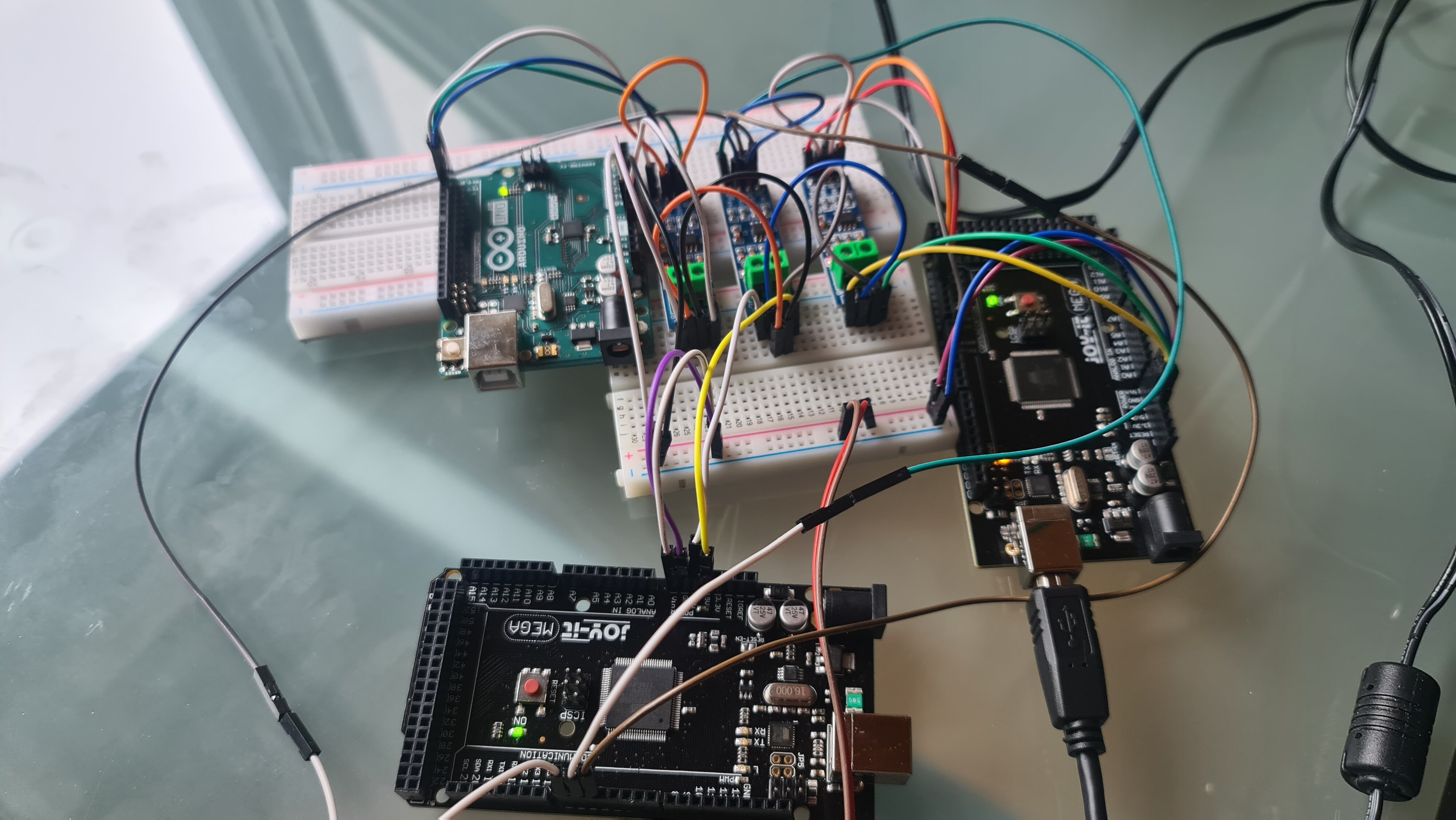
It works!!! I tested 3 slaves. 1 Uno and 2 Megas. Just the Master connected to the PC. The slaves are communicating via the RS485 modules. Gesendet von meinem SM-S928B mit Tapatalk
-
After the succesful test, I designed the PCB's for th RS485 modules. I will connect each board with these micro latch connectors. The screw terminals are for connecting the arduinothe the board. The Red ans blue jumper is for deconnecting the RX ans TX when loading New arduino sketch. Gesendet von meinem SM-S928B mit Tapatalk
-
So i tried it with 1 MEGA as the Master, a MEGA as slave 1 and a Arduino UNO as slave 2. --> it worked! But I had to change the RX/TX on the clone mega's. I wired it exactly as in my picture above exept the slave mega uses TX0 and RX0, as No1sonuk mentioned.
-
you are right. I will try it. Thanks.
-
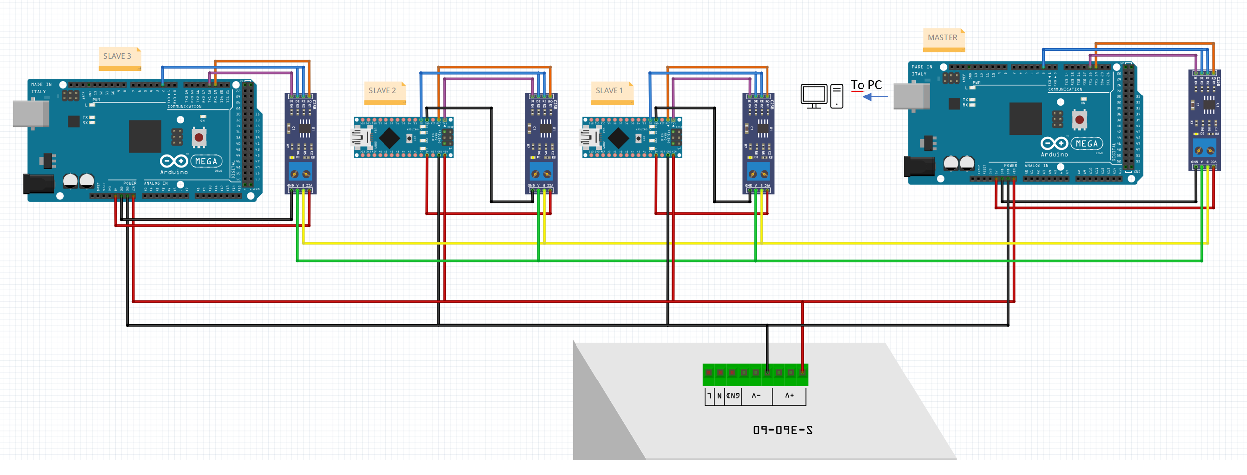
I have now made a diagram of the wiring. Can anyone confirm that this is correct? I think I have read that there can be problems using an Arduino MEGA as a slave? Is this correct?
-
Why the resistor and the condensator? Gesendet von meinem SM-G988B mit Tapatalk
-
2. graphics card for additional HDMI outputs
Rapti replied to Rapti's topic in PC Hardware and Related Software
Thanks a lot for your ideas. Yes in the meantime, I also know, that I only can have 1 driver. So I will return the 730. What should work us having a small AMD Radeon card beside the 4080. Gesendet von meinem SM-G988B mit Tapatalk -
Hello everyone, I would like to control the 5 displays for my F/A-18 simpit via HDMI outputs. Since I don't have enough connections on my RTX 4080, I thought I would install a GEFORCE GT730 as a 2 graphics card. This would give me an additional 4 HDMI outputs. When I plug the card into the PC, it is recognized. The existing RTX 4080 is displayed in the device manager, but has an error. The GFORCE 730 is listed without a problem Nevertheless, I have connected my monitor to the RTX4080 and I also get a picture. I can no longer start NVIDIA Control Panel as it tells me that no device is available. I haven't changed anything on the driver side yet. Does anyone have experience with a second graphics card in the rig?