No1sonuk
-
Posts
1601 -
Joined
-
Last visited
Content Type
Profiles
Forums
Events
Everything posted by No1sonuk
-
Try this: // These need to be at the top of the code int CannonRoundState = 0; // Global variable for checking the state of the light const int CannonRoundLEDpin = 13; // The pin that the LED is attached to // This needs to be in the void setup section: pinMode(CannonRoundLEDpin, OUTPUT); // This goes with the DCS-BIOS code: void onWeaponsCannonRoundChange(unsigned int newValue) { if (newValue != CannonRoundState) { if (newValue==1){ // If the value is 1, set the LED off digitalWrite (CannonRoundLEDpin, LOW); // I'd suggest using pin labels like this to keep track easier } // Just declare them as constants at the beginning of the code else{ // If the value is not 1, set the LED on digitalWrite (CannonRoundLEDpin, HIGH); } } CannonRoundState = newValue; } DcsBios::IntegerBuffer weaponsCannonRoundBuffer(0x1886, 0x0008, 3, onWeaponsCannonRoundChange); I've added previous state checking and the other lines needed to make it work.
-
It might be pulsing because there's no previous state detection in that code I posted. OR Did you remove the original LED code line? If you didn't, one is trying to turn it on and the other is trying to turn it off. BTW, I looked in the DCS-BIOS Flightpanels Fork source code, and there doesn't appear to be a "true" or "false" type option in it.
-
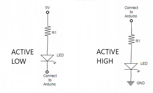
For that code to work, your LED needs to be wired as in the "active high" drawing in my earlier post. Can you draw how yours is connected?
-
Universal military aircraft homecockpit project
No1sonuk replied to Viper1970's topic in Home Cockpits
At work we use a hobby airbrush for doing minor touch-up to paintwork where the big spray gun is too much. That's 3-part exterior paint for commercial aircraft... -
Have a look here: http://robojax.com/node/912 There's a version of the schematic with the diode in place. Just remember that it's placed "the wrong way round" - pointing up. This is so that it won't conduct when the coil is turned on, but it will basically short-circuit the back-EMF when the coil is turned off. The switches thing is a bit more complicated. I've been grappling with a similar thing WRT the bomb, gear and flaps levers of the Mosquito. The problem is that DCS-BIOS overrides the game's control of switches - if it's held on by DCS-BIOS, the game can't override it. This is a problem for switches and controls that the game needs to change automatically. So, my current plan is a kind of hybrid device. My THEORY so far (untested): The Pro Micro and Leonardo can act as joystick devices. You can program them so that the computer sees them as a keyboard or joystick, then you bind the buttons in DCS. A Leo Bodnar board could also be used for the switch input. Then you use DCS-BIOS to read the game's position of the switch and turn on the holding coil. Theoretically, this should make the coil automatically hold the switch when you turn it on, and then release it when the game wants to. So how to read the switches? Switch the control reference view to "advanced" and you'll see output code lines. For the F-18 APU, you get this: void onApuControlSwChange(unsigned int newValue) { /* your code here */ } DcsBios::IntegerBuffer apuControlSwBuffer(0x74c2, 0x0100, 8, onApuControlSwChange); Or this: DcsBios::LED apuControlSw(0x74c2, 0x0100, PIN); Now I THINK you could use the "LED" code line to drive this switch's coil as it only has one position. The 3-position crank one has this: void onEngineCrankSwChange(unsigned int newValue) { /* your code here */ } DcsBios::IntegerBuffer engineCrankSwBuffer(0x74c2, 0x0600, 9, onEngineCrankSwChange); and further up it says the expected values are "0 = held left/down, 1 = centered, 2 = held right/up" You then put some code where it says "/* your code here */" that interpret the number. e.g: void onEngineCrankSwChange(unsigned int newValue) { switch (newValue) { case 0: // Held left/down digitalWrite (CrankLeftHold, HIGH); // Turn on left hold coil digitalWrite (CrankRightHold, LOW); // Turn off right hold coil break; case 1: // centred digitalWrite (CrankLeftHold, LOW); // Turn off left hold coil digitalWrite (CrankRightHold, LOW); // Turn off right hold coil break; case 2: // Held right/up digitalWrite (CrankLeftHold, LOW); // Turn off left hold coil digitalWrite (CrankRightHold, HIGH); // Turn on right hold coil break; default: // failsafe digitalWrite (CrankLeftHold, LOW); // Turn off left hold coil digitalWrite (CrankRightHold, LOW); // Turn off right hold coil break; } } DcsBios::IntegerBuffer engineCrankSwBuffer(0x74c2, 0x0600, 9, onEngineCrankSwChange); NOTEs: My code is written without testing - I am no arduino expert and I don't have the F-18. The DCS-BIOS code comes from the Flightpanels fork control reference, and so some parts may not work in Hub.
-
OK Try this instead of that LED line: void onWeaponsCannonRoundChange(unsigned int newValue) { if (newValue==1){ // If the value is 1, set the LED off digitalWrite (CannonRoundLEDpin, LOW); // I'd suggest using pin labels like this to keep track easier } // Just declare them as constants at the beginning of the code else{ // If the value is not 1, set the LED on digitalWrite (CannonRoundLEDpin, HIGH); } } DcsBios::IntegerBuffer weaponsCannonRoundBuffer(0x1886, 0x0008, 3, onWeaponsCannonRoundChange); Don't forget to leave the LED connected as normal.
-
OK... Let's assume I have no idea about what any of the KA-50 switches or LEDs do. I'll be more specific... What is the name of the switch and/or LED in the DCS-BIOS control reference? Edit: Or even post your code snippet for what you have working.
-
No. The + side to 5V and the - to the I/O pin. In other words, move the arduino from above the LED to below it. The LED will be on if the pin is off. The other method I can think of uses the onchange code with the LED wired the normal way. Which particular LED are you thinking of?
-
I know you can do it in hardware. The arduinos can source or sink enough current for LEDs. See attached. For DCS-BIOS, you'd normally wire an LED as in "active high" - LED comes on when line goes high (on). BUT, if you wire it as in "active low", the LED will come on when the line goes low (off). No code change required - just assume the LED will do the opposite of the pin.

-
If you read a couple of posts above, you'll see he's having trouble with the MOSFET not working properly even when it's not connected to an Arduino.
-
Yup. Seems like the MOSFET is faulty. Though I had expected the 15 M ohms to be much lower. More like 0.5 ohms. Did you include a diode reversed across the solenoid? This kills the back-EMF generated by the coil closing down. It might have killed the MOSFET if the coil is big enough and it worked once or twice. Try getting it working using a light bulb first. There's no danger of that killing a MOSFET with a back-EMF.
-
Yup. To me (electronics engineer) that indicates a faulty MOSFET. Do you have a meter you can measure resistance with? With nothing connected at all, the resistances I get are: Black lead on V- (output), Red Lead on GND (12V terminals) = too high for the meter to read ("OL") on my meter. Red lead on V- (output), Black Lead on GND (12V terminals) = 8.3Mohms If either of those are significantly lower, you have a faulty MOSFET. BTW, I just tried the "disconnected from arduino signal" thing I described above on one of my modules like yours. It worked exactly as I described it should.
-
That's correct. Disconnect it from the arduino. Only connect the solenoid and 12V. The solenoid should be off. If that's OK: Connect the arduino GND to the MOSFET input GND, and use a 5V line from the arduino (not a signal line) to trigger the MOSFET either with a switch, or just touching the wire. If the MOSFET turns on and off when you connect and disconnect the 5V line, the MOSFET is OK. If all that works, try loading the "blink" example sketch and connect the arduino pin 13 (the LED) to the MOSFET signal input line. That should turn the MOSFET on and off with the LED.
-
That wouldn't give four independent outputs, though. As I understand it, each of those switches can only select between one of 12 outputs.
-
Without knowing exactly how the code works, it might give odd results, or not work at all, with just 3 or 4 resistors. You might have to add extra resistance at one end to fool the processor and make the 3 positions the first or last 3 of 12. It could be worth experimenting.
-
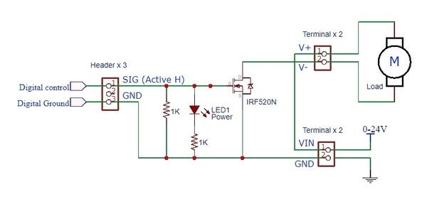
OK. It might be nothing to do with the code... Have you got another one of those boards? It seems to me like the MOSFET itself (the transistor) is possibly faulty. Take a look at the schematic attached. It's a very simple circuit. Your solenoid should be where the motor is shown. With 12V connected to the VIN terminal, 5V on SIG on the input side should turn on the solenoid. Removing the 5V input ( or grounding that pin like an arduino output would ) should turn off the MOSFET. How it works: The LED with 1K resistor in series gives an indication that the input is receiving a voltage. The other 1K resistor pulls the input low to turn off the MOSFET when no signal is present, but is easily overridden by a voltage on the SIG input. There's nothing in the circuit that could turn on the MOSFET without a voltage present on the SIG input. This means that if the solenoid is turned on as soon as you connect the 12V, with no input connection, you have a faulty MOSFET. And FYI, the common fault state for MOSFETs is on.
-
I have some of those drivers, but I've not used them yet. However, all the drawings I've seen of their use show no connection to VCC. Try removing that.
-
Which particular MOSFET board are you using? The first thing I'd do is eliminate DCS-BIOS as a problem. Try this: const int ThrottleStop_Solenoid = 2; //const int is for the coding only const int button = 3; // It doesn't use device memory void setup() { pinMode (ThrottleStop_Solenoid, OUTPUT); pinMode (button, INPUT_PULLUP); } void loop() { digitalWrite (ThrottleStop_Solenoid,!digitalRead(button)); digitalWrite (13,!digitalRead(button)); // Makes the built-in LED mimmick the solenoid output } That should turn on your solenoid and the arduino's built-in LED when you press a button connected from pin 3 to GND.
-
WRT burnout, have you considered a push/pull solenoid? This would need two drivers - one to set the latch and one to release it. In either state, the coils are off, and switching requires a brief pulse.
-
My first computer was a C64...
-
In the joystick library version on the Pro micro, don't you send a "button released" signal? When you do, also send a pulsed "off" button press.
-
Could you not use the Pro Micro to sense the return to centre and send the stop command automatically? Some Bodnar boards have an option for hat switch inputs.
-
A suggestion: Start a fresh thread in this forum (home cockpits) for this question so we can keep this announcement topic tidy and go into detail in a dedicated thread. I don't have the Ka50, so I don't know exactly which controls are used for the switches, but if you can give that info, or the DCS description of the switch, I might be able to find what you need. Also include which DCS-Bios version you're using - I know the Flightpanels version has some additional features on some aircraft that aren't available in the Hub version.
-
Bourns call it a "rotary position sensor". I think that's because it's a potentiometer with no end stop - it just keeps rotating. And without knowing how those wheels work (stops, etc.), it's possible that could be what the real ones use.
-
You CAN use the same pins in multiple DCS-BIOS code lines for different aircraft - I have tried it in a limited way. BUT you have to be careful that there are no address clashes, and the functions have to be basically the same. crash test pilot's warning about instability still applies. I only tested a couple of simple switches and lights. You shouldn't put too much in one device or it could cause issues. Check out my post here and the one following it: