Stickler
-
Posts
266 -
Joined
-
Last visited
Content Type
Profiles
Forums
Events
Everything posted by Stickler
-
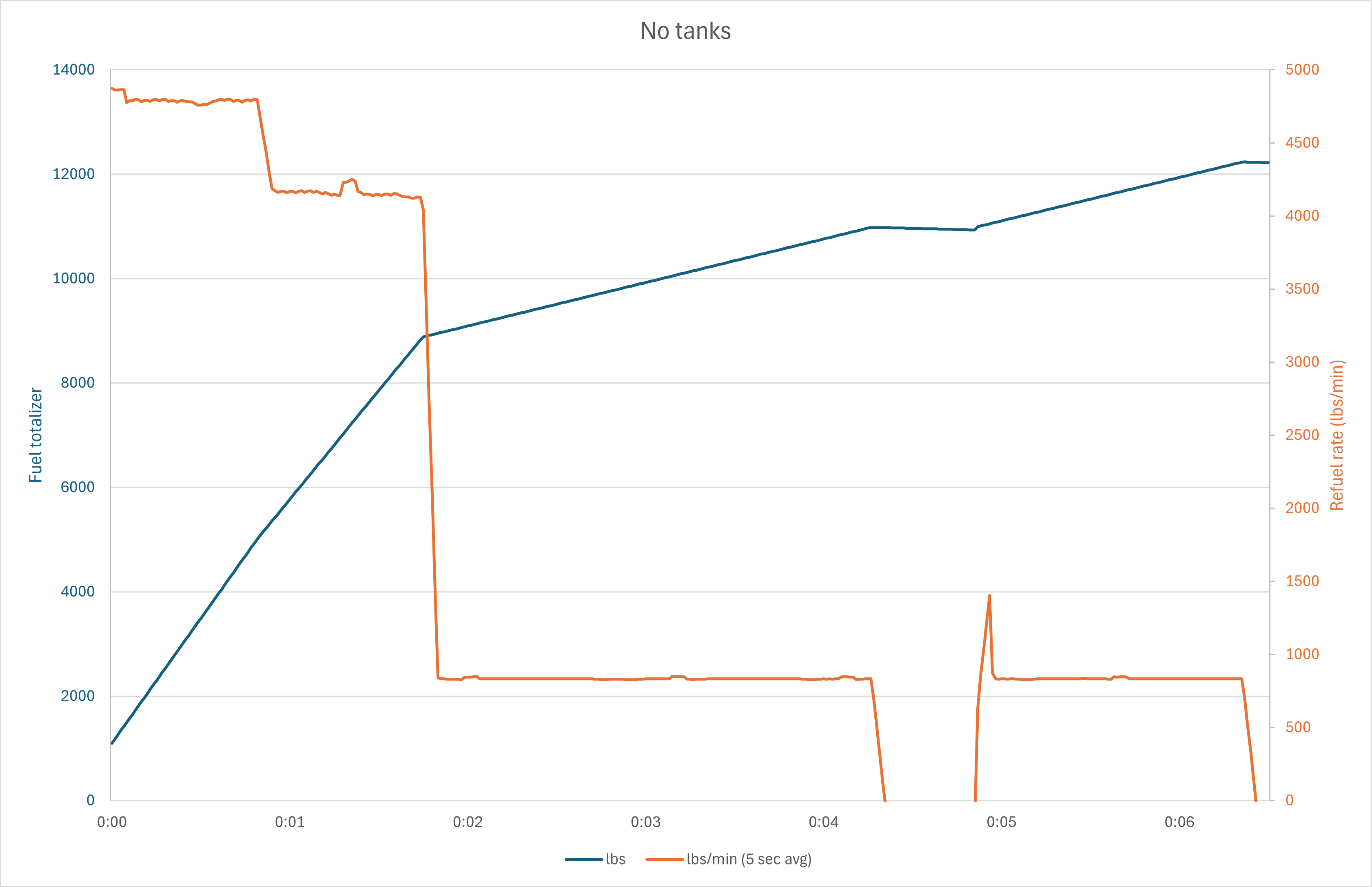
 The game manual (confirmed by the RL flight manual) states that during AAR, fuel can be delivered to the Phantom at a rate of up to 3900 lbs per minute. The attached track recorded on a standard day in a reference aircraft and the corresponding chart below show that the in-game F-4E can be refuelled with up to 4800 lbs per minute. Specifically, this is the case when refuelling either a clean F-4E (shown in track), an F-4E with external tanks and the ALL TANKS/INT ONLY switch set to INT ONLY (not shown in track), an F-4E with a centerline tank and the ALL TANKS/INT ONLY switch either set to INT ONLY or to ALL TANKS (not shown in track). In these cases, refuel rate will be 4800 lbs per minute until the fuel totalizer indicates approximately 5000 lbs. In cases 1 and 2, refuel rate subsequently drops to 4150 lbs per minute until the fuel totalizer indicates approximately 8500 lbs, then to about 830 lbs per minute until the end of AAR. In case 3, refuel rate subsequently drops to about 3900 lbs per minute until the fuel totalizer indicates approximately 8500 lbs, then to about 830 lbs per minute until the end of AAR. AAR_fast.trk
-
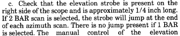
In the F-4E, the position of the elevation strobe indicates the antenna elevation angle. In RDR 2-bar mode, the strobe will jump at the end of each azimuth scan. As shown in the attached track, in the game, this jump only occurs in STAB OUT. Regardless of whether the strobe jumps or not, the actual scan takes account of the RDR 2-bar setting, i.e. the jump can be observed on the radar screen. It's just that the elevation strobe remains stationary except in STAB OUT. elevation_strobe.trk
-
F4 - Route planning tool and WSO - how to?
Stickler replied to mdtenor22001's topic in DCS: F-4E Phantom
Already reported: -
Front seat Radar horizon line Adjustment and wings level indication
Stickler replied to IvanK's topic in Bugs & Problems
While it may be true that the lack of coincidence of the markings is an issue in the real F-4 as well (I don't have a real aircraft immediately available I could use to check), it is certainly not a parallax issue. Regardless of head position, the "zero" elevation mark of the radar symbology is always at the same 1-2° positive elevation scale position (in NORM mode, STAB OUT is a different story of course). On the contrary, in the rear seat, the misalignment can be eliminated with an appropriate head position. -
Front seat Radar horizon line Adjustment and wings level indication
Stickler replied to IvanK's topic in Bugs & Problems
One might add that with the radar scanning along the horizon (elevation +- 0), the elevation bar is not coincident with the 0° mark on the elevation scale in the front cockpit.
-
Thanks for the clarification. Returning to the main question at hand, why does AGC gain out the contact in 100 nm and 200 nm range, but not below these settings?
-
Why does AGC gain out the contact in 100 nm and 200 nm range, but not below these settings? On a related note, I understand AGC to be a feature of track mode (see here). During Manual Search (e.g. when holding the first-stage trigger and not attempting lock-on with the second-stage trigger), we are not in track mode which implies that ACG is not active. I should have mentioned (but this is also visible in the track) that I do not press and hold the first-stage trigger ON the contact, but centered horizontally and vertically on the radar scope with target dead ahead.
-
The attached track shows a B-52 straight ahead at 45 nm. Note how its radar contact is clearly visible in MAP and BRST modes in the 50, 100 and 200 nm range scales as well as when holding the first-stage trigger in MAP mode in scales up to and including 50 nm. Conversely, the contact is not visible when in MAP mode in a greater scale than 50 nm when holding the first-stage trigger. first_stage.trk
-
Reference the attached track showing Jester tracking an F-5 at 100 nm range in BRST mode. This works with all aircraft and ranges, even greater than 100 nm. The problem here is that there is no contact showing on the radar at that range. Jester is magically able to track the F-5 anyway. brst_jester.trk
-
I originally noticed this yesterday during an MP cold-start mission but was able to recreate the issue today in my private LAN with air spawns. Currently, the Air-to-Air TACAN functionality seems to have been lost (it worked in previous versions) between two human-controlled F-4Es. Note the attached tracks, one from the each aircraft involved (the first aircraft acted as the server). With 15Y and 78Y set in the aircraft respectively, I would expect a DME readout to be available. Regardless of T/R or A/A T/R selection with 2x TACAN selected on the navigation control panel, no DME is obtained in either aircraft. I have tried various other channels and the X band with the same result (partially shown in the tracks). This is possibly related to this issue. server-20250721-101432.trkAAT-20250721-101440.trk
-
Unless there has been an undocumented change since 2.9.13.6818, it should be noted that Jester does not currently dispense countermeasures as set on the F/C panel, but in an apparently random fashion. See here.
-
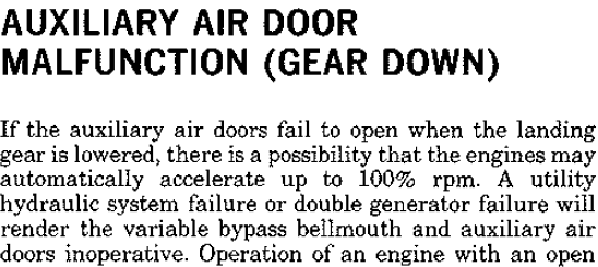
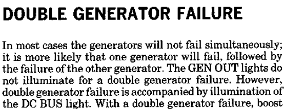
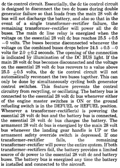
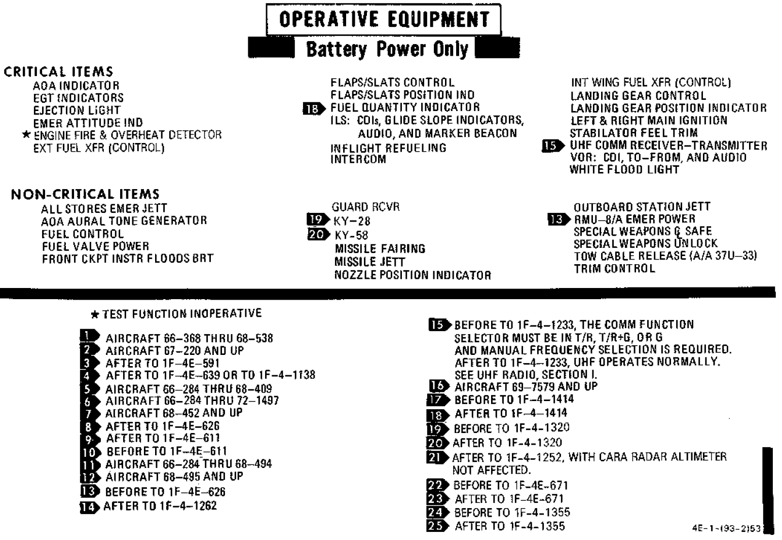
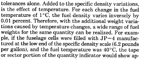
Did more research on this and found some extracts from the RL manuals which indicate that the system may not be modelled completely correctly after all. First of all, if the battery could in general power the Main 28V DC Bus, the speed brakes and the aux air doors would be mentioned in the below overview: The reason why speed brakes and aux air doors are NOT in the list is likely because in case of double generator failure, the main DC line relay is deenergized, thereby disconnecting the Main 28 V DC Bus and the Essential 28 V DC Bus: Or, described in a more comprehensive way: Note that "the dc tie control circuit is designed to disconnect the two dc buses during double generator failure so that loads from the main 28 volt dc bus will not discharge the battery". Since the battery is a 24 V type, the disconnect would occur immediately (24 V is less than 24.5 + 0,5 - 0 V in all cases), regardless of why exactly the RH and LH transformer-rectifiers are no longer powered. An additional hint is provided by the below emergency procedure: If the aux air doors could be operated on battery power, the description would most likely not state that the doors are inoperative with double generator failure. It is noteworthy that a double generator failure should illuminate the DC BUS light, indicating that the buses have disconnected. Note below that the manual only speaks of the battery powering the essential dc bus "for a period of time", not of the main 28 V dc bus. If have not been able to generate a DC BUS light in the game. I suppose it should probably illuminate with both engines and/or both generators off. I have not found a definitive source stating where the light itself gets its power. Based on the below extract it may be tied directly to the Battery bus (as the FIRE and OVERHEAT and EJECT lights).
-
I compiled a list of modes of battle damage by having my aircraft shot at by different weapons while sitting on the ground, and then analysing and aggregating the resulting debriefing .logs with PowerQuery. Every time I run a new test a few entries get added to the list, so the attachment is very likely incomplete, but likely not by much. First of all, kudos wrt the level of damage modelling. Secondly, a few questions: Which system does "Mechanical Failure in Actuator/Actuator" refer to? What is the "Enter No Go Button/Lamp"? Laser Code? Light/DIM Knob, Light/Lamp, Light/PRESS TO TEST Button: Which light is meant? Indicator Failed, Meter/On Off Logic? Which meter? The Meter Switch on the radar panel seems to have its own failures. Power ON Light/Button? Which one is meant? Test Light? Which one is meant? There are quite a few entries for "Broken" circuit breakers. What exactly happens when a circuit breaker "breaks"? Can it no longer be actuated (pulled/reset) or is this "code" or a workaround for the electrical component protected by the circuit breaker no longer working? If the circuit breakers are not "code" as above, it seems that several electrical components do not have their own failure modes. For example, it seems a single generator cannot fail due to battle damage (and not due to ME settings either, as written above). Is this correct or did the generators just happen not to be damaged during my tests? Likewise, it seems that hydraulic failures are not on the list; I was specifically expecting the possibility of hydraulic leaks due to hydraulic lines or reservoirs being hit, more so since fuel and oil leaks seem to be modelled. Are hydraulic leaks modelled? Thirdly, a few possible typos: VHF FM radio total failure: There is not VHF radio in the F-4E. Is the AUX radio meant? AVTR "Door Clicked" and "Tape Clicked". Not sure what that means. "Flare Ligth" "Receiever Pressurised" Damage.pdf
-
[2.9.17.11733] 68-494 or 68-495 fuel system?
Stickler replied to Stickler's topic in Bugs & Problems
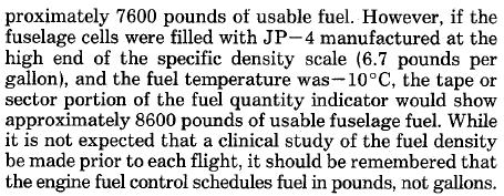
Thanks for your explanation. Could you please provide answers to my three questions above though? With regard to the actual amount of fuel that fits into the tanks depending on density, based on a quick test, the indication shows 12150 lbs in a fully fuelled reference aircraft at sea level both in low density conditions (OAT 50°C, QNH 28.35) and high density conditions (OAT -12.4°C, QNH 31.10 inHg). This seems to contradict your statement and also the manual:
-
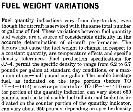
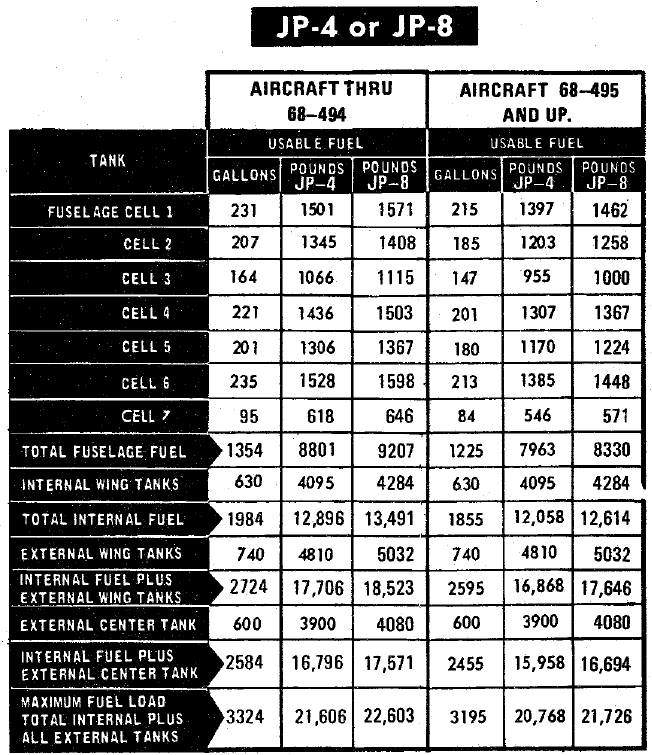
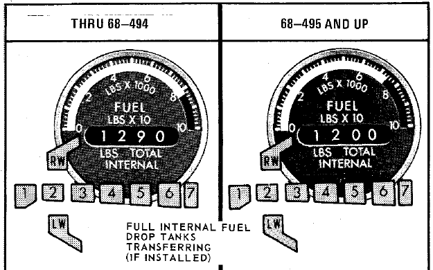
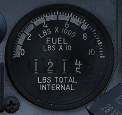
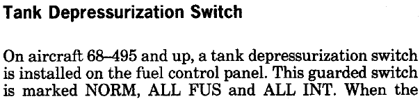
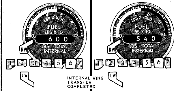
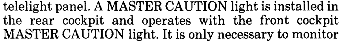
This is at the same time a question and a bug report. According to RL Dash-1, the F-4E had the following fuel capacities: null Given that the following is the fuel quantity indicator of a fully fuelled jet in-game, it appears as if 68-495 and up is intended to be modelled. Then again, the most visible feature of 68-495 was the introduction of a tank depressurization switch which is not modelled: Thus: Which fuel system is intended to be modelled? Could the tank depressurization switch be added or the fuel system be retrograded to 68-494 for consistency? Which fuel levels nominally show on Heatblur's fuel tape and fuel counter when cells 5, 6 and the wings are empty? 5348/5966 or 4862/5408? For the rounded Dash-1 figures see below.
-
[EU TZ] 526th vTFS (CJTF-13) looking for procedure-oriented F-4E crews
Stickler replied to Stickler's topic in Jets Squadrons
Sample checklist pages from EP section added. -
Feedback Thread - Phantom Patch 21-05-2025
Stickler replied to IronMike's topic in DCS: F-4E Phantom
The WSO's throttle still does not move for me when I move the pilot's throttle using an axis in a multiplayer session (did not try keyboard, since this would require me to unbind my throttle axis to prevent interference, which I have no time and interest in doing). The only thing that does seem to work is that the pilot's throttle moves when the WSO moves his, but only when using the keyboard, not when using an axis. -
Except for the oscillations no longer being present, no change to the above behaviour in 2.9.16.10973.
-
The first option is correct.
-
NAVAIR 01-245FDD-I, 10-14, contains the following question in the NATOPS test question bank: "111. Actuation of the warning lights test switch by the RIO will illuminate the pilot's master caution light. T I F". According to my research, neither NAVAIR 01-245FDD-I nor TO 1F-4E-1 contain a definitive answer whether the above statement is true or false. The statement that comes closest is the following: This would seem to indicate that whenever the front cockpit MASTER CAUTION light illuminates, the rear cockpit light will illuminate as well. It is not clear whether the reverse is also true, but it would appear logical if it were. In the game, actuating the warning lights test switch in the rear cockpit will illuminate the WSO's MASTER CAUTION light, but will not NOT illuminate the pilot's MASTER CAUTION light, and vice versa. Thus, the current implementation is not necessarily incorrect, but as a low priority item it might be worth checking the wiring diagrams.
-
Some additional information: Observe the attached tracks recorded with a reference aircraft on a standard day, no wind, with four TLADD pull-ups using different AoA and note the pitch and climb angle (pitch minus AoA) at which the horizontal bar starts to move out of view: # Timestamp Pitch AoA Climb Angle 1 38.866 34 0.6 33.4 2 32.072 34 0.4 33.6 3 25.285 36.1 2.5 33.6 4 24.952 39.2 5.3 33.9 This indicates that the criterion for the horizontal bar starting to move is neither pitch nor climb angle hitting 38°. The most consistent value seems to be the climb angle, but this is nowhere near 38°. tladd_1.trk tladd_2.trk tladd_3.trk tladd_4.trk tladd_1.acmi tladd_2.acmi tladd_3.acmi tladd_4.acmi
-
AFCS Cannot be deactivated by pulling stick (not sure it's bug)
Stickler replied to Miro's topic in Bugs & Problems
I can confirm the first part of the report (didn't check the second part). Looks like this bug is back. -
TO 1F-4E-34-1-1, p. 1-22, states: "b. TIMED LADD (and TIMED LEVEL) - Operate voltage is applied to the PULLUP timer; then to RELEASE timer at the termination of the PULL UP timer countdown. For the LADD mode, the PULL UP timer must be set on some value to get the ADI pullup schedule; the RELEASE timer must be set to develop a bomb release signal." TO 1F-4C-34-1-1, p. 1-122A (the F-4E part), states: "Voltage is applied only to the pullup timer in the LOFT or TIMED O/S modes. In the TIMED LEVEL and TIMED LADD mode, both timer circuits are energized, providing the pullup timer is not set on zero. In the TIMED LEVEL and TIMED LADD modes, the release timer must be set to obtain the release signal. (The release timer may be set on zero for the LOFT and O/S modes.) Completion of the pullup timer energizes relays which provide the various pullup signals and the pullup flight path program." In the game, you will obtain a TL release with the release timer set to zero; in fact, if the pull-up timer is also zero, the bomb release button acts as a pickle button (instantaneous release). Based on the above extracts, it is unclear whether a release timer > 0 was required to obtain weapons release. This is therefore not a bug report but a recommendation to check your wiring diagrams or ask for SME input.
-
- 1
-

-
[2.9.15.9599] Bombing calculator erroneous Bomb Range calculations
Stickler replied to MagicSlave's topic in Bugs & Problems
It‘s a bug. Please reference -
As per the title. Conversely, the aircraft spawns airborne, in takeoff position or during hot ground starts with the altimeter properly RESET.