Stickler
-
Posts
266 -
Joined
-
Last visited
Content Type
Profiles
Forums
Events
Everything posted by Stickler
-
 Confirming the STBY flag issue which I happened to stumble upon as well. Unfortunately it's not just an aesthetic issue since at night this makes it almost impossible to know if the altimeter is in STBY or RESET (the "STBY" flag shows in both cases, albeit with a slightly different shade).
 -
[Known isuue] Throttles Aren't Modeled Correctly...
Stickler replied to mytai01's topic in Bugs & Problems
I would like to add that contrary to what the manual says (Engines - Heatblur F-4E Phantom II), the WSO cannot currently shift the throttles from OFF, but can enter the afterburner range. -
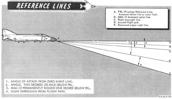
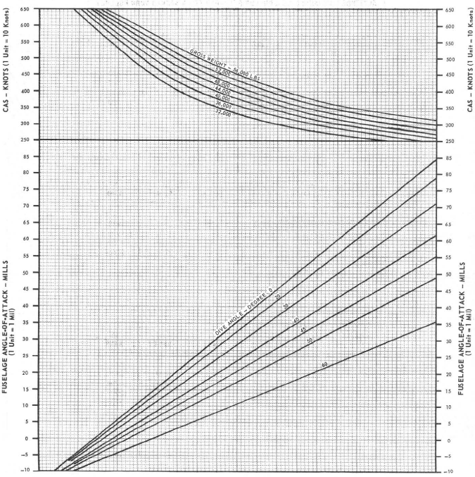
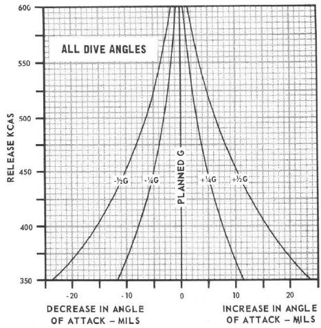
Based on further testing, the in-game AoA is approximately 39 mils LESS than the AoA of the real aircraft as taken from the above chart under identical conditions. This is true in the speed range of 400-500 KCAS. With lower speeds, the difference decreases. The difference is most pronounced (around 41 mils) with high gross weights and least pronounced (around 37 mils) with low gross weights. Dive angle seems to have a negligible effect on the difference. Thus, for a one-size-fits-all, easy to apply fix, subtract 40 mils from the AoA obtained from the above chart, then add the result to the sight depression obtained from the bombing calculator to obtain the actual required depression. This is provided you keep your release KCAS in the "usual" range of 400-500 KCAS. Based on the attachments, the ZSL and FRL seem coincide in the F-4E.

-
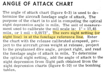
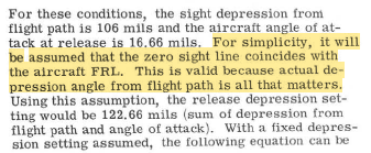
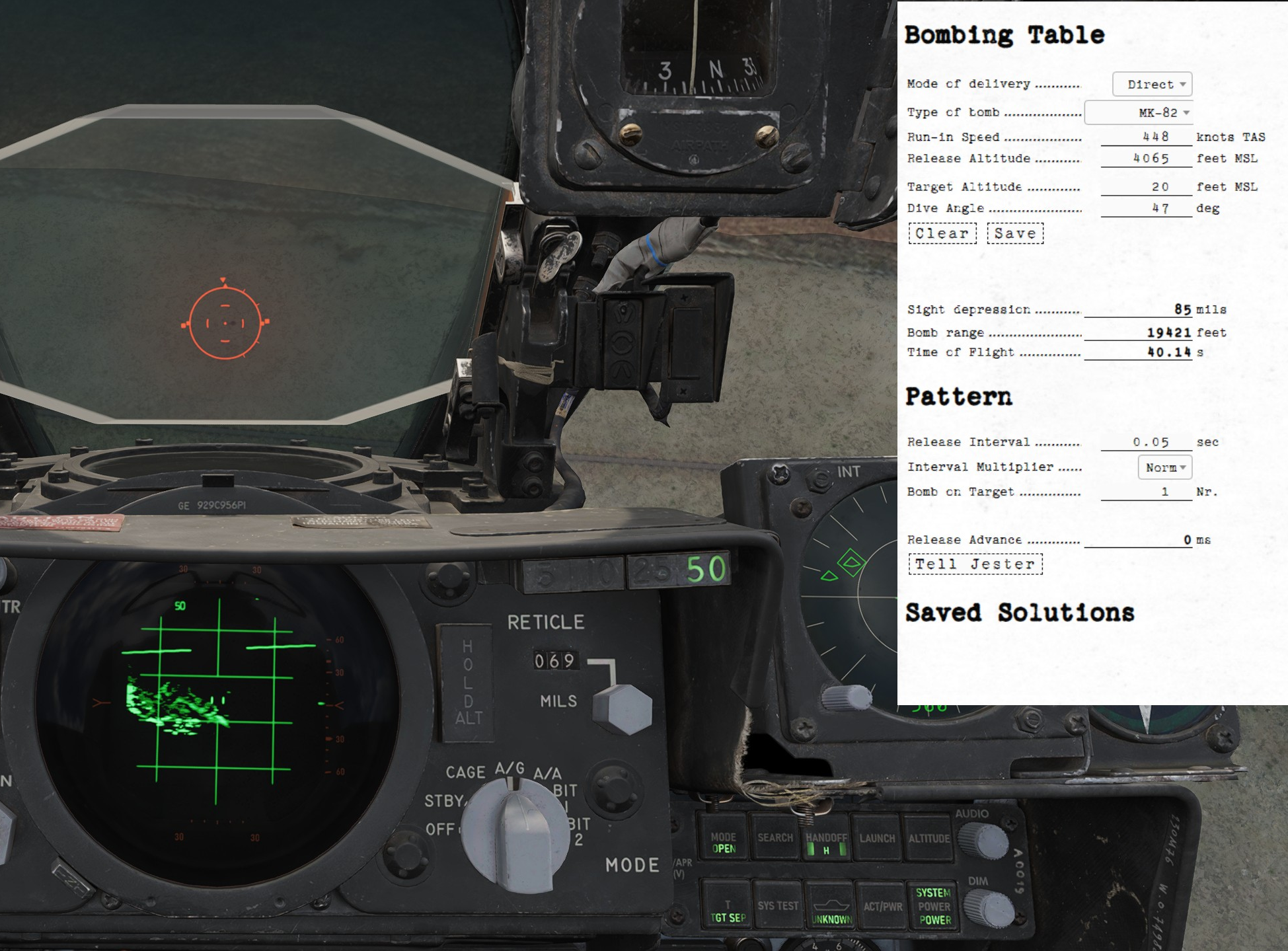
I would like to add my own observations here. Reference the following release: Disregarding that the calculated bomb range and TOF are completely off (that's not the concern of this post), note that the calculated required sight depression is 85 mils. This calculation is confirmed by my own bombing calculator (which uses in-game bomb cx values determined from testing) when inputting the same parameters (plus/minus 1 mil). Observe also that the "correct" depression required (see the crater near the reticle) is 69 mils. Release CAS was 425. At release, my G per the F2 view was 0.8, versus a nominal G of 0.68 for a 47° dive angle. As per the correction chart below, this approx. 0.1 G error introduces a sight depression error of approximately 2 mils. For simplicity's sake, I'll ignore it. At the time of release, the aircraft's gross weight was 47717 lbs as per the mission editor (I set unlimited fuel to make sure). As per the below chart, the aircraft's AOA should have been 17,8 mils (rounded 18 mils). To compensate for this AOA, the actual sight setting would have had to be 85 + 18 mils = 103 mils, thus even further from the actually required sight setting. This makes me believe that the simulated F-4E's AOA diverges significantly from the real F-4 at given parameters. Note that if you were to subtract 18 mils from 85 mils, you would approximately get the really required 69 mils, but this is a coincidence based on other tests with different release parameters. It is entirely possible that I'm completely misunderstanding how the above calculations should work, so if anyone spots a flaw in my logic please help me out.
-
Just to confirm, as soon as the RWR is patched the LAUNCH button functionality will also be implemented? Radar Warning Receiver - Heatblur F-4E Phantom II "In the event a missile launch is detected by way of discrete SAM guidance commands being received, the MISSILE LAUNCH indications in this button (4) will illuminate, and a circle is superimposed around the threat emitter defined as guiding the inbound weapon. Pressing the button while illuminated will provide launch audio through the intercom." If the LAUNCH button is meant to be able to be pressed once the patch is out, I recommend to also add a key binding for that button which currently does not exist.
-
2.9.5.55918 (MT) Flaps airspeed switch set incorrectly
Stickler replied to Stickler's topic in Bugs & Problems
This is based on multiple attempts dedicated to analysing this specific issue. Re-made the mission to verify it is not something with the .miz and also created different aircraft in the same mission. Tested with reference and non-reference aircraft and obtained more or less the same results every time. Track with reference aircraft attached. To be clear, the 215 KIAS in my OP meant the speed indicated on the ASI. When referencing the F2 view, the "IAS" displayed there at which the flaps move does seem to change somewhat depending (possibly) on altitude. As far as I know (but this might be module-dependent), the "IAS" in the F2 view is actually EAS. This might have something to do with it. In any case, in all tests there was virtually no difference between the accelerating and decelerating case. speedswitch.trk -
Depending on the source, the flaps airspeed switch is set at 235±5 knots accelerating and 220±10 knots decelerating, 237±7 knots accelerating and 15±5 knots below accelerating speed (decelerating), approximately 240 knots accelerating and approximately 220 knots decelerating. In the game, the flaps will extend and retract at 215 KIAS accelerating and decelerating.
-
The "Empty" loadout in the mission editor has a "Weapons" weight of 223 kg/492 lbs. When manually removing all pylons, "Weapons" weight is not zero, but -288 kg/-635 lbs. From this I deduce that some pylons, but not all of them in the same way, are considered as part of aircraft weight. I would appreciate a clarification regarding how pylon weights and drag are being considered in the mission editor and the flight model.
-
The TACAN test as described in Navigation Test Procedures - Heatblur F-4E Phantom II does not work in that the indications that follow the "Observe the following" cannot be observed. Tested at Kutaisi with an otherwise functioning TACAN.
-
The air refuel receptacle is connected to the Essential 28V DC Bus so it needs at least one engaged Engine Master Switch to be powered by the battery if no external power is available. The receptacle further needs utility hydraulic pressure. In the game, the receptacle can be operated without an engaged Engine Master Switch, without external power and without hydraulic pressure.
-
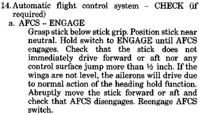
As per TO 1F-4E-1, 15 October 1984, Change 10 - 1 April 1990, p. 2-13 (see below), abruptly moving the stick forward or aft should disengage the AFCS on the ground. In the game, the AFCS only disengages upon abrupt stick inputs in the air.
-
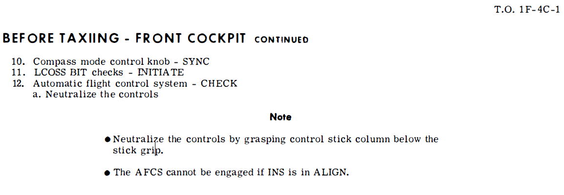
According to T.O. 1F-4C-1, 1 October 1970, p. 2-27 (see below), the AFCS cannot be engaged if INS is in ALIGN. In the game, the AFCS and altitude hold can be engaged if INS is in ALIGN or even OFF. Also, AFCS does not disengage if INS is active and then set to ALIGN or OFF. With the INS in ALIGN or OFF, there is no apparent degradation in AFCS performance. The note in the attachment cannot be found in any other F-4 manual available to me, so it is possible this limitation does not exist in mod states other than the ones the manual applies to, but it would seem logical that the INS is required for the AFCS to function. This is supported by the checklist sequence (same for all F-4 variants I have checked) per which the reference system selector is to be set to PRIM (after the INS is in NAV) prior to checking the AFCS.
-
When turning the VOR/ILS frequency rotaries in the front seat clockwise, the associated number decreases. When turning them counter-clockwise, the number increases. This is the exact opposite of all other similar rotaries in the F-4E I have tested so far and in other jets generally. I have not found a specific piece of information in RL manuals concerning whether the above is correctly simulated or not, however due to the departure from usual practice I'm flagging this as a possible bug. Track attached. vor_knob.trk
-
[EU TZ] 526th vTFS (CJTF-13) looking for procedure-oriented F-4E crews
Stickler replied to Stickler's topic in Jets Squadrons
With the release of the module now having been announced for May 21st, 2024, here's your chance to get in right from the start. -
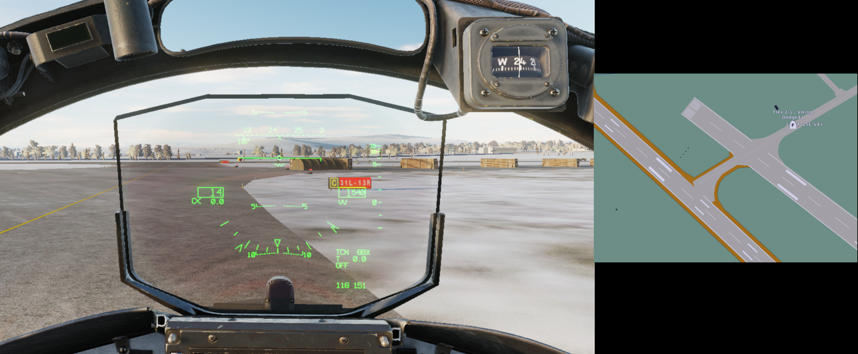
The introductory video at the 0:34 mark says that Heatblur's "vanilla" F-4E is the 45-MC. According to the game manual, the aircraft simulated has a maximum internal fuel of 12896 lbs: Tanks - Heatblur F-4E Phantom II According to TO 1F-4E-1, 1 Feb 1979, p. 1-12 (attached), the maximum usable internal fuel of Block 41+ aircraft is 12058 lbs; the 12896 lbs is correct for Blocks up to 40. Also, the manual mentions 315-gal wing tanks here: Engines & Fuel Systems - Heatblur F-4E Phantom II. I have no record of 315-gal wing tanks being used on the F-4E and I suppose 370-gal is meant here as on the other page of the manual linked above.
-
[EU TZ] 526th vTFS (CJTF-13) looking for procedure-oriented F-4E crews
Stickler replied to Stickler's topic in Jets Squadrons
526th vTFS is now open for applications. -
I've been preparing documentation/doctrine for an F-4E squadron within EU Milsim Battalion – The Art of Warfare (tawdcs.org) since November. Check out the recruitment thread: Key facts: Milsim European Time Zone Squadron based on 526th TFS, Ramstein AB, Germany Based on/using available real-world documentation/procedures as far as possible/practicable
-
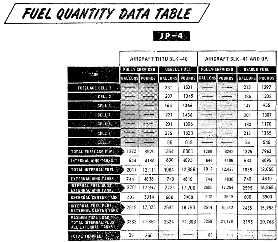
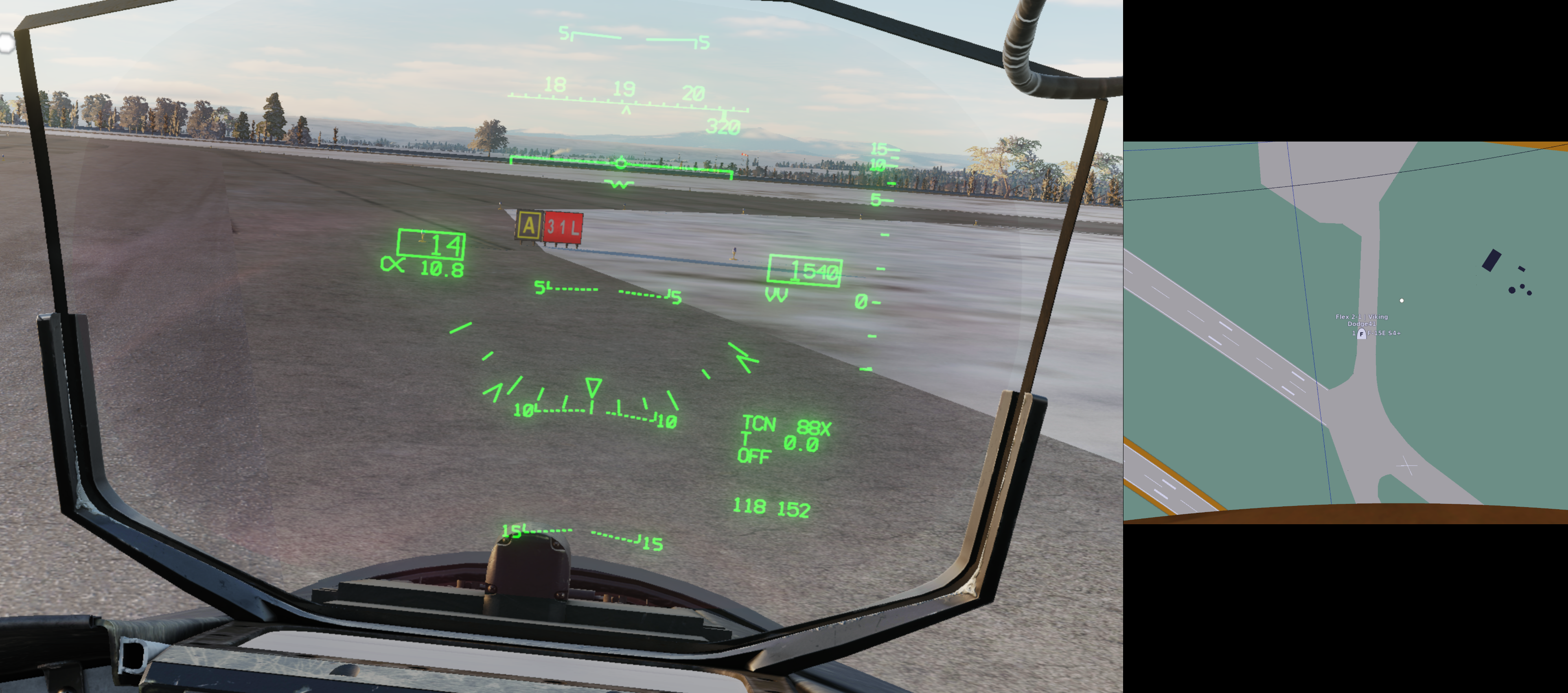
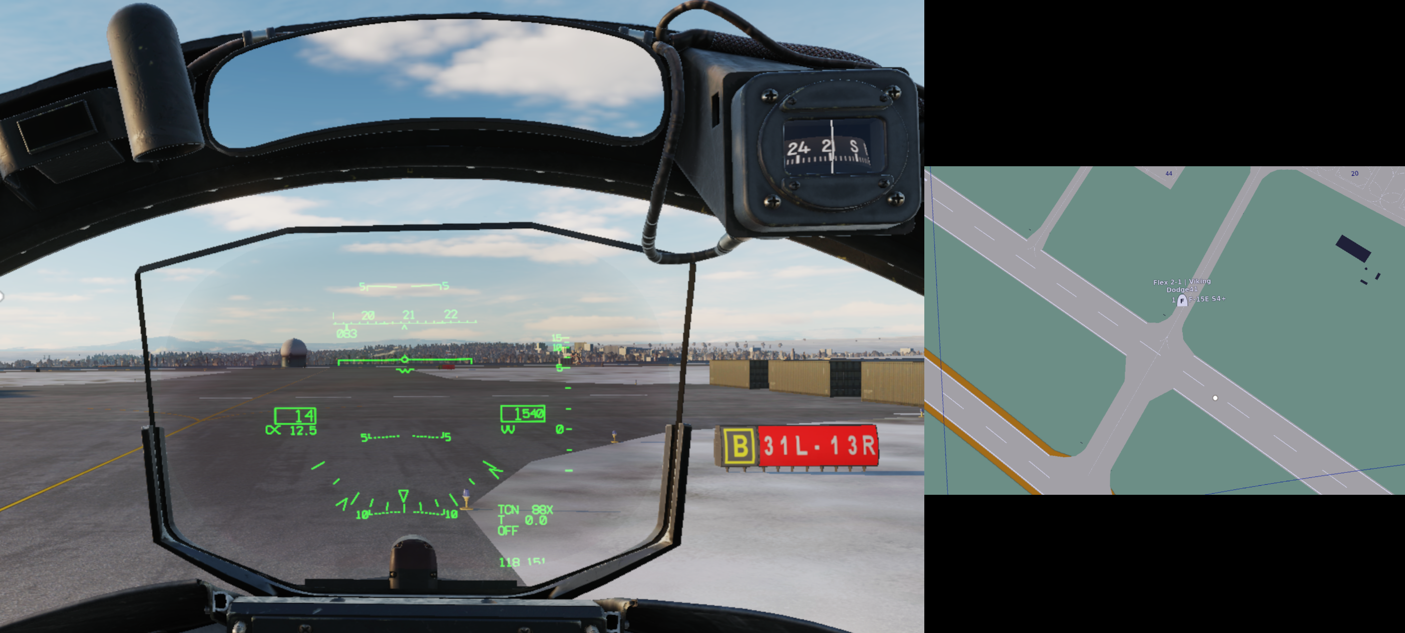
Observe the following screenshots: Note how in the first situation, RWY 31L is indicated whereas the player is located in front of RWY 31R, in the second and third situations, RWY 31L-13R is indicated whereas the player is located in front of RWY 31R-13L.
-
The screenshot below shows me on a perfect 3° glide path to Tbilisi RWY 13R using the Mirage F1's autopilot. Note how the PAPI left of the runway indicates 4 red. To get 2 red, 2 white at Tbilisi RWY 13R in DCS, one needs to fly a glide path of approximately 5°. According to the RL Georgia AIP, both the PAPI and the ILS glide slope are calibrated to an angle of 3.5°. Haven't checked RWY 31L.
-
[DCS ISSUE] Mk 20 Rockeye canister not (always) opening
Stickler posted a topic in Bugs and Problems
I'm aware that the Mk 20 Rockeye is currently incorrectly simulated as clearly demonstrated by any 34-1-1 of your preference featuring the Mk 20 and by Karon's extensive testing (The Mk-20 Rockeye Cluster Bomb: Observations – FlyAndWire). However, until today I assumed that the incorrect simulation was at least consistent, but alas this assumption seems to be unwarranted. As shown in the attached .acmi featuring two Mk 20 lofts with very similar release parameters and trajectory, the first canister opens while the second does not. No switch settings were changed between the releases. Can anyone explain the logic? Is this problem specific to the F-14 or does it affect DCS in general? rockeye.acmi- 1 reply
-
- 1
-

-
Tacview, the ACMI for DCS World – Official Thread
Stickler replied to Vyrtuoz's topic in DCS Modding
Noticed the following discrepancy in 1.9.1 (not sure if it existed before) which is best explained watching the attached .acmi: When the aircraft is in a pull-up, the pitch as indicated by the HUD view aircraft symbol and the "Pitch" value in the Telemetry window seem to match exactly, which is as expected. Conversely, the γ value seems to lag the flight path marker quite a bit. For example, when the flight path marker in the attached .acmi reaches 20° nose up, the γ value is approximately 17,8°. Shouldn't these values be the same? Which is the "correct" indicator for the physical flight path of the aircraft, the γ or the position of the flight path marker? pull-up.acmi -
The following observations are from 2.8.4.39313 (MT), not tested in other versions. All values are approximate. RALT bug (ft) - Warning tone/light (ft) 450 - 450 800 - 900 1000 - 1800 2000 - 3000 3000 - 3900 The warning tone/light therefore come on significantly before they should based on the RALT bug setting. Occurs in SP and MP.
-
Sorry to necro the thread, but in which way are GBUs affected by the EFUZE setting in the game (not asking about RL) other than the fact that setting the EFUZE to SAFE will cause them to dud?
-
Tacview, the ACMI for DCS World – Official Thread
Stickler replied to Vyrtuoz's topic in DCS Modding
.acmis attached as requested. HEI.zip.acmiAP&HE.zip.acmi -
Tacview, the ACMI for DCS World – Official Thread
Stickler replied to Vyrtuoz's topic in DCS Modding
Reporting another issue related to the F-14, but this time it looks as if the problem is really on the Tacview side: When selecting the different F-14 M61A1 ammunition types in the mission editor, the following ammunition is shot as per Tacview: 20 mm HEI: M56A3_HE_RED 20 mm API: M53_AP_RED 20 mm AP&HE: M56A3_HE_RED 20 mm TP: M55A2_TP_RED According to my post in the F-14 bug forum, everything SHOULD be correct on the F-14 module's side. I'd appreciate if you guys could check your code, maybe there's a simple typo that causes the issue.