Pilum
-
Posts
382 -
Joined
-
Last visited
Content Type
Profiles
Forums
Events
Everything posted by Pilum
-

[CLOSED] Climb rate appears to be to high, even for 109k
Pilum replied to KenobiOrder's topic in Bugs and Problems
Targeting 23 m/s? I thought you said 25-26 m/s? -
[CLOSED] Climb rate appears to be to high, even for 109k
Pilum replied to KenobiOrder's topic in Bugs and Problems
Yup, I agree and if the P-51 is to have historically correct climb rates then we want the same for the K4 right? :thumbup: -
[CLOSED] Climb rate appears to be to high, even for 109k
Pilum replied to KenobiOrder's topic in Bugs and Problems
Good and that is a step in the right direction but still too high IMHO. Anyway, thanks for update! -
[CLOSED] Climb rate appears to be to high, even for 109k
Pilum replied to KenobiOrder's topic in Bugs and Problems
Well on this we have to disagree: Exhaust thrust is included in my calculation and without it the climb rate for the K4 at 1.8 ata would be around 21.5 m/s i.e. 1.8 m/s lower. So since exhaust thrust has a significant effect on the climb rate I have no doubt whatsoever that neither Focke-Wulf nor Messerschmitt would publish a climb chart without this effect included but I’m wiling to stand corrected if proof to the contrary can be produced. :) -
[CLOSED] Climb rate appears to be to high, even for 109k
Pilum replied to KenobiOrder's topic in Bugs and Problems
Since this is OT I will not delve in it but yes I agree this looks optimistic and I would expect lower climb rates for the P-51 under these circumstances. -
[CLOSED] Climb rate appears to be to high, even for 109k
Pilum replied to KenobiOrder's topic in Bugs and Problems
As input to deciding what climb rate to target, here are some C++ simulation results for 1.8 ata. I think the sea level climb rate for 1.8 ata in the attached figure may actually be a bit optimistic since I get around 26.5 m/s with 1.98 ata at sea level which is more optimistic than the Messerschmitt calaculations posted earlier. Me109K4 climb rate and time 150518.bmp -
[CLOSED] Climb rate appears to be to high, even for 109k
Pilum replied to KenobiOrder's topic in Bugs and Problems
Any news on this? As I recall from earlier forum discussions there is a broad consensus that the K4 is climbing too well which also seems to have been acknowledged so what are the developers plans? What is the sea level climb rate for MW50 enabled at 1.8 ata being targeted? Is a fix in the works? -
[CLOSED] Climb rate appears to be to high, even for 109k
Pilum replied to KenobiOrder's topic in Bugs and Problems
K4 climb rate fix status? How is the climb rate issue coming along? There was a dedicated thread that was closed 2015-01-15 with reference to the issue being acknowledged and planned to be fixed but the bug thread is still classed as [REPORTED] not fixed or resolved. So what is the status for this issue and what are the plans? Given that the thread was closed more than 3 months ago it would be good with a short status report if possible. Thanks! http://forums.eagle.ru/showpost.php?p=2290166&postcount=1 -
Well I think you should be careful before drawing too firm conclusions about the power on stall characteristics based on these power off figures because adding thrust changes the equation: The power off stall figures will be governed mainly by the amount circulation type lift the wing can produce and in this arena the F-14 can be expected to shine with wing set a moderate sweep. This is also most likely why the F-14 does so well in STR performance in the mid Mach range because the wing can generate a lot of lift utilizing circulation type lift which can be had for a relatively cheap price in terms of drag. At least in comparison to the vortex type lift component added by the strakes on an F-16 or F-18 at higher aoa. So to get a better understanding of how the F-14 and F-15 compare in really slow speed high aoa turning and how well they generate vortex lift, it would be good to see some power on stall numbers instead. This would be especially interesting to see since at such low speeds as M=0.25, i.e. high aoa, vortex lift is an important facilitator and it may well be that the F-15 has an advantage here but without power on data it’s hard to tell. So if someone has access to these numbers this would be really interesting to see. Disclaimer: Note that my interest here is a purely academic and that I’m not advocating that either plane should actively seek out this part of the envelope. :smilewink:
-
I think I’ll limit myself to answer this objectively and skip the diatribe: Returning the compliment about paying attention: If you pay attention to what I have said it is this: Just because the top g-load/bank angle chart does not tally with the turn rate chart this does not automatically mean the lower turn rate chart is wrong: Yes, it could mean that the curve in the lower chart showing a turn rate of 13 deg/s is too high. However, could also be that the upper curve showing 2 g 60 deg bank should be a tad higher so you would read off 2.2 g 63 deg bank instead. So to me it means there is an inconsistency and that one of the charts is incorrect but you can’t really tell which. Finally, as to insulting, the only insults I can see here have been about wasting other people’s time, references to Topeka Country Fair and that people who don’t agree should study map projections.
-
Gee, why come out with guns blazing? Why the bold text and extra sauce added? I'm not saying the chart is 100% correct. Just floating some ideas here so no need to get defensive. ;) Taking things to the extreme:Say I have a bank angle of 90 degrees in a turn and pulling max aoa in the turn on the edge of stall. In this case, if I have a sufficiently powerful engine I can still maintain altitude by body lift. In this case I will have a certain finite turn rate and load factor that could be measured by flight instrumentation. However, mathematically I am dead since I am flying with 90 degree bank and therefore at an infinite load factor. So maybe both the load factor and turn rate were measured in flight tests? If so then that could explain the difference we see in the charts: While the load factor (acceleration perpendicular to wings) measured by flight instrumentation was 2, the bank angle was actually slightly more giving a higher turn rate and the altitude in the turn was maintained by a slight beta. Just a theory of course, and it could also be that the turn rate in the figure is higher than it should but I can't really see that how you can be so dead sure either way just because the figures don't tally.
-
One explanation for the 11.4 to 13 deg/s difference could perhaps be that in the unbanked stall the wing and power component of the engine thrust is doing all the lifting but in a banked turn the wing lift could be supplemented by a vertical lifting component due to a yaw angle beta coupled with the resulting engine thrust component which theoretically means that you could have a slightly higher bank angle than 60 deg and still maintain altitude.
-
Ok, that the missile would have different flight profiles for different ranges makse sense: No need to loft if the shot is closer ranged since the burn time of the engine is 27 s there is plenty of energy to allow a high speed proportinal navigation intercept in the horizontal plane as well. So it sounds logical that the fire control system in the AWG-9 radar would most likely then have some kind of grading of the commanded flight profile from a horizontal shot at close range to a high loft at extreme ranges. OTOH I guess the AIM-7 would be used unless the longer legs of the Phoenix is needed and what's close for the Phoenix might mean quite long for the AIM-7. About the guidance in the end phase the idea that the missile would dive down early and not attack from above sounds interesting. I guess it makes sense in a way since it makes it easier for the on-board radar to aquire the target with more clear sky as background instead of major ground clutter. However, if the AWG-9 radar is able to maintain lock all the way then the missile radar should have both range and doppler info making it easier for the on-board missile radar to lock-on since both the range- and velocity gates in the missile know in which bins to expect the target given that this should be extractable from combining the radar measured range and speed with ditto from the missile INS. OTOH given the small aperture of the missile radar antenna the main- and sidelobe clutter may be troublesome so maybe the missile really needs to dive down to be closer to co-altitude to the target. Guess it also depends on the type of target? A Tu-95 should give quite a heft return but I guess it's different if the target is a fighter and in addition, I wonder if it really was in the AWG-9's capability to lock up a figther sized target at 120-180 km? Anyway, the main thing I wanted to point out is that the kinematic FM of the Phoenix in DCS right now seems to be way too optimistic and since the Mig's R-3R is AFAIK scheduled to be adjusted (see link below) then the Phoenix FM will also need some TLC. Just to improve the Phoenix's kinematics would be a step in the right direction but too also get the long range guidance closer to IRL behaviour would of course be icing on the cake. http://forums.eagle.ru/showpost.php?p=2308197&postcount=1
-
I actually tried extending the range by a more cruise like flight: In this case the missile transitions to 0.9 load factor at apogee and it does fly longer: 175 Km as compared to the 135 Km in the scenario the figure in post #29 depicts so it flies longer but the flight time is very long: 273 s and it is basically out of energy only doing M=0.9. Read somewhere that the battery time on the Phoenix was in the order of 200 s but not sure about that. In addition, I agree about the intercept: The scenario modeled in #29 is purely theoretical for max range and for a more lethal shot the missile needs to have more energy when it comes down. Say, the Tomcat was to launch at 136 Km instead, then the missile would hit the target 132 s later at a respectable 1985 Km/h or M=1.84 after flying 110 km.
-
Why don't you think the missile would fly like I modeled? I think the way it flies now would be pretty efficient: First, get up as fast as possible into thin air to reduce air resistance, so go for 45 deg loft. In this phase no need for lift, i.e fly at 0 deg aoa to reduce drag even further. Then when at apogee, start flying at best "glide ratio" to extend flight further than when going 0 g load factor all the way. In fact, I can get the missile to fly even further by increasing aoa at apogee, e.g flying at 0.9 g load factor, but then it's much slower when it comes down to do the intercept. So what would in your opinion be a more efficient efficient flight path than the one I run now? Maybe I could model it and see how that would compare?
-
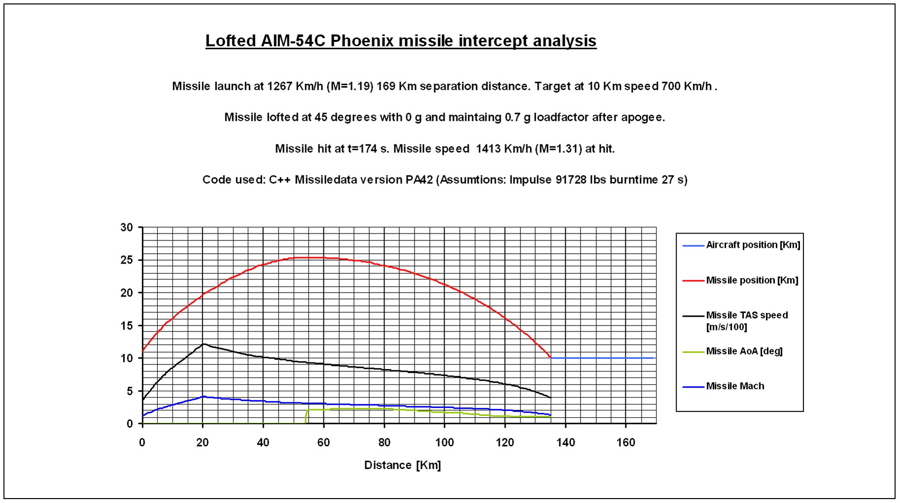
Attached is a track with an AI controlled F-14 launching an AIM-54C at an AI controlled Tu-95 at a distance of 180 Km. The track shows the missile accelerating to an astounding TAS= 6700 Km/h (M=6.3) and it is only lofted to an apogee of 20 Km altitude at which point it has a speed of M=5.4. It then decends towards the target and slams into the Bear at M=3.5! This type of missile performance is more in line with what you would have expected to come of the rails on an X-wing scrambled from Tatooine rather than a missile launched from a Tomcat and my guess is that an Admiral in the USN would have given his right arm to get his hands on this type of hypersonic missile. :smilewink: Attached is also what I think is a more realistic AIM-54C performance estimate, now based on the new impulse estimate of 91728 lbs for the Mk47 rocket motor as per data based on post #15. Note that this scenario is very optimistic even though launch range is 169 Km not 180 Km since the missile has a modest M=1.3 at impact and any manouvering by the target would defeat the missile. I have tried to come as close as possible to the launch scenario in the DCS track in the attached C++ simulation but as can be seen, a more realistic estimate of the AIM-54C performance is nowhere close to the current performance in DCS. Looks like the Phoenix flight model needs some major tweaking. F14A long range AIM54 Tu95 kill.trk

-
Hang-on: I just noticed that the the AIAA 2011-6941 document Winfield_Gold linked earlier states “364 lb Flexadyne propellant” for the Mk47 rocket motor so this also tabs well with the 360 lb in the Hazard doc. This would then indicate that the impulse for the AIM-54C would be in the order of 364 x 252 = 91728 lbs, i.e. in the order of 83% of what I assumed (110577 lbs) in the AIM-54A simulation in post #1.
-
Ok, but it stills seems strange with the lower fuel weight 360 lb for the C when the A is listed as 459 lb......
-
Yes for sure the cross section can vary and the calculation I did earlier was just a ballpark estimate but the point was that I was calculating it as solid but that still did not amount to more than 168 Kg and therefore not close to the 200.8 Kg stated for the A model. Secondly, while you can to some extent tailor the thrust due to the area burning, you can't change the specific impulse and it seems the Phoenix was in the order of 252 s which is close to really high smoke propellants that AFAIK top out at 265 s. I find it hard to believe that the C model had a 459/360 higher specific impulse, i.e 321 s to compensate for the lower fuel weight.
-
Yeah, I'm with you about the impulse only being valid at one altitude but I have assumed SL for all my data and I compensate for altitude so at 10 Km it will be more than the numbers we are talking about here and I assume the 252 s figure for the specific impulse is SL.
-
Thanks all for the input and links, lots of good reading and interesting info there! Some more thoughts beginning with the AIM-7F Sparrow: From the SMC for the Sparrow AIM-7F dated January 1977 we have the propellant weights 52 lb for boost and 82 lb sustain, i.e. 135 lb total or 61.3Kg. This tabs well with the figure of 132.901 lb "NEWQDLB" weight in the Hazard document: HAZARD CLASSIFICATION OF UNITED STATES MILITARY EXPLOSIVES AND MUNITIONS U.S. ARMY DEFENSE AMMUNITION CENTER, REVISION 15, JUNE 2012 VG26 RCKT MTR ASSY, MK58-7 AIM-7 SPARROW (37) 1.3C 0186 7 132.901 60.2827 More from Hazard document: “C. The NEWQDLB is sometimes less than the total explosive content of theitem because testing has shown that all the explosive does not contribute to quantity distance computations. Such items are identified by NOTE 4 in the "NOTES" column.” Since there is no “Note 4” for either the Sparrow or Phoenix rocket motor assembly this would imply that the Hazard doc really lists the actual propellant weight contained and not some explosive equivalent. AIM-54 has two entries for rocket motor: V877 PROP SECT, MXU-637/B, F/AIM-54A PHOENIX 1.3C 0186 7 459.000 208.199 V885 PROP SECT, MXU-637A/B F/AIM-54C PHOENIX 1.3C 0186 C 360.000 163.293 So this would imply that the C model only has 163.3 Kg propellant while the A has 200.2 Kg which seems a bit strange seeing the C is claimed to have better range than the A…… In addition, the AIAA 2011-6941 document Winfield_Gold linked above, shows a Mk 47 motor assembly that is supposed to be 15” by 70”. However, since 15” is the diameter of the missile itself and figure 5 in that document shows that there are lugs sticking out the actual diameter of the propellant must be less than that. Eugene Fleeman’s book Tactical Missile Design gives the density of 252 s solid fuel at 0.062 lb/in**3 or 1718 Kg/m**3 so a ballpark calculation assuming the propellant part of the motor is 40” of the total 70” length with a diameter of 14” would be in the order of 168 Kg which tabs pretty well with the 163.3 Kg in the Hazard document. However, I would have thought that the upgrade to modern electronics from AIM-54A to C model would have freed up some space for more propellant not less? OTOH, that upgrade purportedly introduced better ECCM, improved guidance and control section, strap down inertial guidance etc so maybe this took up more space than before? In addition: About the interchangeability of the rocket assemblies, note that the A version motor has the designation MXU-637/B while the C version has the designation MXU-637/A/B so maybe the B here indicates that it can be fitted to the AIM-54A as well which would explain why the maintenance manual say they have the same motor? However, I don't get why the AIM-54C model would have only 79% of the fuel weight of the A and still have same or better range given that the C is even heavier? So as they say, still confused but on a higher level…..
-
Ok, that is interesting info. Do you have a source for that because it would be good to understand the background since reverse engineering those figures and assuming a specific impulse of 252 s (I = 4000 lb x 30 s= 120000 lbs and 120000/252 = 476 lb fuel or 218 Kg) this would lead to a motor weight which is not too far from the one I have assume for the AIM-54A which was 200.8 Kg. Also, 142 Nm seems really long and would most likely involve both a supersonic launch and target. In addition, the target would have to have a pretty big RCS to be able to get a lock-on at +260 Km :)
-
Yep, in order to get a 100 Nm plus range you need a really co-operating target going in a nice straight line. Any manovering on the part of the target will ruin your day. Tnx! and yes, it would be good to get a discussion going because while I think the actual flight model is OK there is a good amount of guesswork when it comes to the input such as launch speed, loft angle, missile drag etc so it would be good to narrow this down a bit.
-
Excellent stuff Prilller, thanks for sharing! :thumbup:
-
Open sources indicate that the Phoenix has a range in "excess of 100 Nm" which is quite extreme and one can wonder in what type of scenario this would be possible? I have over the years developed a C++ program that can calculate missile kinematics and lately I have fiddled around a bit with a AIM-54A model testing out different launch speeds, loft angles, missile aoa during flight, target speed etc and come up with the attached scenario which indicates that it is at least quite possible from a missile kinematics perspective: The scenario in the attached figures is a head to head engagement with a target doing M=0.67 at 10 Km which AFAIK is the cruise speed of the Tu-95 Bear and the F-14 doing M=1.4 with a launch distance of a little over 190 Km, i.e. "in excess of 100 Nm". One figure is true to scale and the other scaled up to improve reading of flight data. I have simply reverse engineered this so I have no idea if this is close to the IRL launch profile used to attain the range "in excess of 100 Nm" but the simulation certainly shows that it is within reason and in addition, my simulations indicate that with an even higher loft angle and higher launch speed the missile intercept can be moved out even further. So, does anyone have more info or input that could help improve the simulation and shed some light on really long range missile intercepts? I have used open sources to come up with the following missile data for the AIM-54A: Missile drag: Lacking solid data here this is tricky and since it is short stubby missile it is difficult to come up with a good estimate based on comparisons with other more slicker missiles. So with no solid data to go on I have assumed a drag area (Cdo x reference area) varying between 0.04-0.11 m**2 depending on missile Mach. Impulse: 492480 Ns burntime 27 s. Have no idea if the Phoenix has a boost and sustain phase or if it is a continuos burn so for the time being thrust is assumed constant at around Impulse/burntime = 18000 N. Impulse calculated as the product of fuel weight and an assumed 240 s specific impulse. Burntime pulled out of a figure on the internet, no idea if that is correct. However, the data on the fuel weight seems more solid: AIM-54A fuel weight 200.8 Kg generously provided through open source US defence document "Hazard Classification of US Military Explosives and Munitions" rev 14, June 2009." :music_whistling: Simulated loft angle and launch speed: Pure guesses, but open sources indicate that the missile peaks out between 80 and 100,000 ft so I think I'm in the right ballpark with my 91,000 ft. I think getting this as close to IRL performance as possible in DCS would be nice and since the Leatherneck developers actively participate in forum discussions I thought some input to the Phoenix modeling may not hurt. So any constructive input to improve the C++ simulation and/or understanding of long range Phoenix shots would be welcome: Are any of the assumptions unreasonable and is there more data out there that could be used to improve the simulation and modeling in DCS? AIM54A1488kmhloft.bmp AIM54A1488kmhloftscaled.bmp