Pilum
-
Posts
382 -
Joined
-
Last visited
Content Type
Profiles
Forums
Events
Everything posted by Pilum
-
Yes, the Me109 had a combination of a fin offset and an unsymmmetrical profile to balance torque. IIRC then this was set to give no sideslip at some cruising speed and could be adjusted somewhat with the trim tab IRL. How will this be implemented in DCS? To a set trim speed or will it get trimmed to the "spawn" speed?
-
I guess you would need a lot more cooling if you are running at high hp output like the K4's with MW 50 boost did so in those cases you would most likely need all the cooling you could get, at least on a hot summers day in the climb. So it seems strange to limit the radiator cooling performance. However, could well be that they reduced the max opening in colder operating conditions. I guess it would make sense to have a smaller max opening in wintertime for example. As an analogy, in colder climates it is not unusual to cover up the radiator intake on your car in winter time to allow the engine to get up into suitable operating temperatures. BTW: Has there been any info on what boost the K4 is getting? I would assume it's the 1.8 ata we will see in DCS?
-
I don't remember the source offhand but IIRC they both were similar in that they had what is called a forward loading camber, i.e. the camber line was not arched in a circular fashion but had the maximum height of camber further forward compared to more conventional profiles. This gave them the characteristic that made them popular with designers at the time: A lower pitching moment than more conventional rear loading camber profiles which in turn lead to lower trim forces and less need to retrim with speed. However, AFAIK the NACA 230-series and also the similarly cambered 2R1 had good high Mach number characteristics, but that was purely fortuitous and not by design. This was also true for the Mustang laminar profile and the Spitfire also did well but that was not due to the profile but due to the thin wing section used. So interestingly, they all had rather good profiles in terms of compressibility characteristics not by design, but by chance. ;)
-
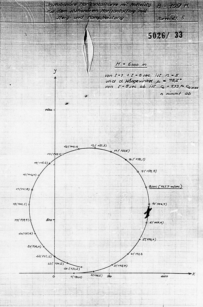
The only thing I have on high speed Clmax for the Me109K4 is a momentaneous turn diagram (attached) in which the Clmax is given as 1.13. The diagram states that the loadfactor 5 is held up to 8 s into the turn at which time there is a transition to a Clmax of 1.13. Since the speed is 161.7 m/s at this time this translates to about M=0.51 at 6 Km altitude so a point value for the K4 if taken from this diagram is Clmax 1.13 at M=0.51. So a good starting point for the Me109K4 would IMHO be a low Mach Clmax of 1.40-1.45 reduced to around 1.13 at M=0.51. Incidentally this tabs rather well with some wind tunnel tests NACA did on a NACA 230-series profile (similar to NACA 2R1) aspect ratio 6 configuration which seeing it incorporated twist and had different profile thickness was somewhat different but still had quite similar Clmax at both these speeds: Clmax=1.45 at low mach and Clmax=1 at M=0.5.(See NACA Wartime Report WR-L-51 page 22 figure 8.) http://ntrs.nasa.gov/search.jsp?R=19930092809

-
Yep, I agree: We should take a step back and give DCS some peace of mind because SW development is hardly a linear affair is it? While you could work out an average SW development speed for a team over the project as a whole, when you zoom in on a day to day basis the progress is more stepwize, especially when you are close to releasing the SW and you are chasing bugs. In the end you may have one serious bug left only and you may solve it in an minute or it may take days. So, based on the feedback DCS got last time :ranting: when they were a day or two late compared to a date which was probably their best estimate, I completely understand and sympathize with their decision not to give a firm date.........
-
Well I guess everyone understands that conceiving more realistic AI is a very challenging proposition and that this would of course be the best solution but I really think that a simple fix like a dynamic pressure limitation to the current AI model could improve peoples perception of the AI quite a bit and in addition would not need any additional processing power or require a rewamped AI coding.
-
Ok, thanks for the update. Sounds good that this is being looked into! Considering that all other aspects of this sim are so great it would be good news indeed if the DM was tweaked some. Another area that would be nice to fix is the uber-AI that hang up there at 100 km/h in perfect control. I realize that changing their fundamental behaviour may be difficult but one fix I can think off is to limit the lowest speed (dynamic pressure really) that they could operate at so they would be a bit more evenly matched to human pilots in terms of control ability, say limit the lowest dynamic pressure they could fly at to something like 200-250 Km/h at SL. Couldn't something like that be scriptet in? The way the AI are jerking around now in perfect control and reversing on a dime at extremely low speeds is really frustrating....
-
Well in the same vein as I just posted an opinion in another thread that I think the DCS crosswind modeling should be aquitted because there is data supporting the current behaviour of what can best be termed as a reversed weathercock effect, I think the DM is guilty as charged: Why? Because there has been a substantial gathering of data in tracks that show that you on AVERAGE need in the order of four to five times more hits to bring down an AI in DCS compared to the IRL statistical average. There is historic data indicating that about five 20 mm hits or twenty 50-cal hits were needed to bring down a fighter on AVERAGE. So no one is saying that every time you hit with this number the enemy should go down but if you collect a large number of tracks that all indicate that an AVERAGE that is four to five times higher than the historical AVERAGE is needed then STATISTICALLY the model is off. Or course this is just another opinion but I would say this one happens to be based on evidence so in this particular case I support an overhaul of the DM which IMHO is guilty as charged. Finally, it will be very interesting to see how the Mk108 in the Me109K4 will fare on this point when it is released in DCS because on AVERAGE you should only need to hit with only one 30 mm shell to bring down a fighter. The continuous allegations about gunnary accuracy that people that point this weakness out receive is moot and pretty lame IMHO: The question at hand is the number of hits needed not the accuracy. If you are a good shot you can reach the level of hits needed quicker that's all. The problem at hand is how many hits are needed. Taking the conversation in this direction is just a smokescreen obscuring the real problem. And yes, I have seen the excuses that the hit count "could" be showing something other than what is stated and yes, different types of shells have different damage potential when hitting in different places and this could explain some deviations but if you STATISTICALLY in most cases need four to five times as many shells as historical sources would suggest then something is definitely off.
-
Well when you compare the spindly gear on the 109 with the broad footprint of the 190 I guess we can look forward to a steep learning curve :smartass:
-
It will be very interesting to see how difficult mastering takeoff and landing will be in the K4 . Seeing the difficulties we had with the supposedly more docile Dora and making a projection based on this I guess we will see quite a few tracks ending with smoking craters and one or few threads on the subject of how correctly the K4's landing and takeoff characteristics are modelled.:joystick: But I could be wrong of course.......:music_whistling:
-

Please fix that deflected propwash effect :-(
Pilum replied to Anatoli-Kagari9's topic in DCS: P-51D Mustang
Well, note that I'm covering my bets cause I'm not saying it's right or wrong just that it's difficult to be sure either way and I believe an aquittal is the way to go if there is insufficient evidence ;) -
Please fix that deflected propwash effect :-(
Pilum replied to Anatoli-Kagari9's topic in DCS: P-51D Mustang
Well yes and that was my point: I think what we see can actually be explained by theory and while it may be counterintuitive it may very well be the correct representation :) -
Please fix that deflected propwash effect :-(
Pilum replied to Anatoli-Kagari9's topic in DCS: P-51D Mustang
Jcomm: I was actually writing this reply to your post in the Me109K4 thread but I see you updated that so I post my reply here instead. OTOH I guess this is the more appropriate place for it anyway :smilewink: Weather the "reverse" weathercocking effect you refer to is a true representation of how a high hp single propeller fighter aircraft should behave or if the modelling in DCS is lacking I will not make a judgement on. Especially since I have not tried this out myself in DCS. That being said, I do believe based on your description it may actually be correctly modeled: That a power application can act destabilizing in yaw is I believe well documented: You can find a number of NACA reports by Herbert Ribner on the subject, e.g. NACA Wartime Report L-219 Propellers in yaw etc. So in a scenario where you have a strong sidewind from your 3 O’clock, this will cause a sideforec acting ahead of the c.g. to your 9 O’Clock if power is applied. If this is enough to overcome the weatherwane effect I will leave left unsaid but I don’t think it’s as implausible as it may sound. While the NACA reports provide the theory, I think there is also an intuitive way to look at this: If you think of momentum theory and think of the aircraft being enveloped in a slipstream tube, the air is being sucked into this momentum tube from the right being this deflected to the rear. Looking at this picture from above it’s similar to the deflection of air by a wing and the resultant force should analogously be forward to the left, i.e. roughly to your 10-11 O’clock. Since to my understanding the DCS model is quite accurate in modelling slipstream, it may be so that what we see in the sim is actually a correct representation since there is definitely a connection to theory on the destabilizing effect of high solidity propellers such as we see on the Dora and Pony. OTOH a model is always a model and it may be there are simplifications that have resulted in this effect being more pronounced in DCS than IRL. However, I don’t see that we have any basis to say this so and it may very well be so that what we have in DCS is the real deal. So to conclude, I think we should take care in passing judgement on the crosswind behaviour of aircraft currently modeled in DCS and consequently expect the Me109K4 to be any different. -
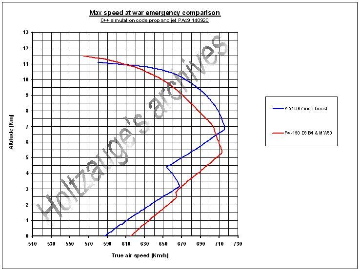
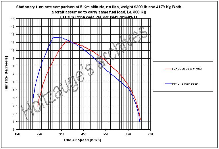
I posted some turn rate charts for the Pony and Dora from my C++ simulations a while back but now that the K4 is coming I thought it would be good to revisit this and look into what to expect. Note that I have assumed the same fuel load for all three aircraft in the simulation in order not to penalize the P-51 for it’s great internal fuel capacity. Paradoxically, even with a lightly loaded Pony it looks like the K4 is still the turnfigther in this company. Usually we may not think of the Me109’s is this context but here it certainly looks like that. OTOH, the 1 Km altitude turnrate figure shows that the Dora and P-51 have a speed advantage, at least if we assume 75” boost for the P-51 (638 Km/h at 1 Km) so there should always be the option to disengage for the Pony. However, the simulations indicate that the 67” boost P-51 with 611 Km/h versus the 1.8 ata K4’s 607 Km/h at 1 Km will certainly be hard pressed down low. So DCS P-51 drivers that have read historical pilot account’s of P-51’s outturning Me109’s on a regular basis and intend to use that in DCS better beware. At least that is my prediction: If DCS keeps in tradition and models the flight dynamics correctly then K4’s will outturn the P-51ingame. OTOH maybe there are other opinions on this? What should we expect to see when the K4 is released? Which will be the better turnfighter? :smilewink:
-
Concerning the accuracy of engine mounted cannon, the Ta 152 flight manual (Flugzeughadbuch Ta 152 H-0/H-1 Schusswaffenanlage teil 8A) page 37, states the following allowable dispersion for the Mk108 in ground testing: "100% of the rounds for an 11 round burst shall hit within H=35 cm and B=30 cm at 100 m range." (My translation) This is pretty darn accurate. In fact it is even more accurate than for the wing mounted Mk 151/20 which had an allowable dispersion of H=60 cm and B=100 cm for a 22 round burst. Also, remember this is the 100% area and since it make sense to assume a normal distribution within the 30x35 cm area, the pattern is pretty tight. So the engine mounted Mk108 is in fact more accurate than the Mk151/20 we have in the Dora now. Granted this is the Ta152, not the Me109K but I don't think the results would be much different: The key issue is most likely the engine mount: You have a huge mass to which the cannon is mounted which results in less movement than for other types of installation like in wings. I posted about the Mk108 accuracy earlier in this thread to preclude that DCS follows in the same sorry path as previous sims like EAW and IL2 and model the firing Mk108 as jumping around and spraying shells all over the place ..... Will be very interesting to see if DCS breaks traditions here and models the Mk108 as the instrument of precision that it apparently was or if we will see the return of the blunderbuss :)
-
Awesome skin! Thanks for sharing! :thumbup:
-
P-51 MP vs Speed Question and Concerns about Power/Thrust
Pilum replied to USARStarkey's topic in DCS: P-51D Mustang
Looking from external view F2 it looks like the radiator is quite open in the track you posted. While this is expected in the climb condition, I would not have expected that in the high speed case. At high speed I would have expected the radiator to be more closed since the high speed ram pressure will ensure a high flow of air through the radiator anyway. The ram effect will do two things: one being to raise the pressure of the air in the duct which is good since it promotes more heat transfer due to the higher air density, the other being a raised temperature due to the compression of the air in the duct which of course is not good. However, since the ambient temperature at 24 kft would be in the order of 240 deg K (-33 deg C) there should still be quite good cooling since the ram air temperature would still be low: To/T= 1 + (1.4-1)/2*M**2 To= 240(1 + 0.2*M**2) To=240(1+ 0.2*0.63**2)=259 K or -13.7 deg C Po/P= (To/T)**3.5=1.31 Po=1.31*0.37=0.48 bar So while air pressure is only 48% of sea level pressure, the effective cooling temperature goes down to -14 deg C at 24 kft 440 mph (Assuming 15 deg C ambient at sea level). I did a run a sea level (attached track) and the top speed was quite close to the expected: around 580 Km/h or 360 mph. However, if you look at the external here you will see that the radiator is more closed than at the 24 kft run. So while the historical sea level speed of 360 mph seems to be attainable in DCS with radiator in auto, the speed at 24 kft seems a bit lower than historical data would imply and one explanation for the discrepancy could then be that the radiator is in DCS modeled as more open at 24 kft than 0 kft for extended periods at WEP. How realistic this is I don't know and I guess that depends on the thermal modeling. However, I think the important thing here is the relative performance: If the P51D is now a bit slower than historical at 24 kft I think that is OK as long as the Fw190D9 is also slower than historical, i.e. that the relative performance is maintained. If this is so then a few percent deviation is quite OK I think. We have to remember that DCS is a model, not reality and as a model it is by far the best yet! :thumbup: Attached is my C++ simulation estimate of the relative performance and while the Dora is faster at nearly all altitudes with these power settings, the Pony should be in the order of 10 mph faster at 24 kft. speed run 0 kft ver 1.trk
-
Yes, from the chart it looks like as long as the Dora stay's above 380 Km/h TAS at 5 Km altitude it turns better. Also, I have not done a speed comparison but from the turn chart it looks like the Dora is faster (very slightly that is!) even than the 75" Pony at this altitude :)
-
Here you go!
-
Yes, I could do that but why 5km in particular? :)
-
Correction: Unfortunately, it turns out that the P51D best turn time estimate of 21.2 s and figure in post #180 was actually for 9600 lb not for 9300 lb as the figure says. I realized I had used my default setting of 9600 lb instead of the 9300 lb that should have been used in the comparison with the Dora for the reasons as outlined in post #154. The shortest turn time for the P51D at 1Km altitude is now with the correct 9300 lb weight reduced to 20.6 s and the doghouse chart now looks more as expected with the P51D showing a substantial advantage in both turn rate and radius. I think the figure is also interesting in a general sense since it graphically illustrates the point that any given plane can be made to turn faster by adding power, albeit at a higher speed.
-
Sorry, I don't have the stick force report in English translation. The one I have is in German and I got the English title from the microfilms first cover page. On the Me109 roll rate report I may be able to help you: I have a copy with quite good images. PM me which page/pages you need and I'll see what I can do.
-
Thanks to USStarkey I got some 75" boost Packard Merlin V-1650-7 data and have now run that in the C++ simulation: I was actually expecting the difference in turn rate to be larger but the P51 at 75" boost does now have both the smallest turn radius and also turn rate although maybe the difference is not as big as expected: The shortest turn time for the P51 is now with 75" boost circa 21.2 s which is better than both the Anton and Dora. However, maybe it's not so strange that the difference is not larger than it is because while the P51 certainly has a lower wingloading, the Dora still has a 13% higher P/W ratio even with the Pony at 75" boost. Also, looking at the figure it is seems that the top speed at 1 Km altitude is nearly identical if Pony has 75" boost since the turn rate curves for both aircraft above 555 Km/h are now superimposed. The C++ speed simulation at 75" boost now gives the Pony a speed at sea level of 613.5 Km/h or 381 mph. At high altitude (6.2 Km or 20,340 ft) 732.1 Km/h or 455 mph. Think I've seen the 380 mph low alt figure somewhere before but I don't have any historical data on the high alt figure though. P51D Fw190D9 stationary turn rate PAF PA49.bmp
-
You have made three posts in this thread now Kurfurst: #127, in which you termed the British RAE measurements as guesswork, the Charles Meudon wind tunnel tests as useless and our efforts here as "guesswork countered by guesswork". You followed up with #170 which speaks for itself and now #178 above which is a continuation on the theme. Just where in this muck is there an iota of constructive input? By your own admission you don't want a fight so why don't you do everyone here a big favour and just go away so we mere mortals can get on with our "guesswork"?
-
OK, that sounds reassuring because I have had some bad experiences in a couple of “legacy” sims where even a shallow dive in a Me109 at around 8 Km to BnZ a B-17 resulted in “compressibility” problems and an inability to pull out and zoom after an attack even though both q and Mach was not that high. So good to hear that this is under wraps in DCS. :thumbup: BTW: One good source on elevator stick forces and Mach limits is a report by Prestele: Me/VB/Re/10902E94 in translation “Relationship between Mach number and stick forces on Me109 and Fw 190” and I assume that you have that one already? If not let me know.