Pilum
-
Posts
382 -
Joined
-
Last visited
Content Type
Profiles
Forums
Events
Everything posted by Pilum
-
I hope no one falls for the OFF TOPIC Spitfire trolling posted above. Seriously, if you feel an urge to diss the Spit even before it is released then by all means start a dedicated whining thread on that but pls don't mess up this thread where the topic is the 109's trim controls. Thank you.
-
I agree that it makes sense that the NII VVS test most likely had the trim tab in a neutral position if nothing about the tabs was mentioned in the report. In addition, I have no reason to think otherwize than that the current DCS Me109K4 is correctly modeled when it comes to cg, response to elevator and trim changes etc so don't get me wrong, I'm not critizicing, I'm making a suggestion for a refinement :smilewink: The point I want to make is that the trim tab on the trailing edge of an elevator is a powerful tool to change the trim and that small adjustments of the tab will give significant changes in the trim point. In addition, I see no contradiction either to the NII VVS test, restored 109's flying today or the current model of the K4 if the elevator trim tab in DCS was to be digitally tweaked slightly. In fact, I just took the DCS K4 for a ride and concluded that it is very close to being fully trimmed at high speed with the adjustable tailplane only and looking at the external, the change of elevator angle required to trim is barely noticeable. So, seeing the very small change of elevator needed to trim, I think tweaking this in the DCS model would be the correct thing to do since IMHO an IRL 109 pilot would no doubt ask his crew chief to do this.
-
That one flew over your head did'nt it? :smilewink:
-
Yes but a competent "calculator" will certainly spot that the CG is not "fixed" by design but will change depending on the girth of the test pilot!
-
Otto's is right. By adjusting the elevator trim tab you can change the trim point of a plane without changing the angle of the adjustable tail plane. So if the authority in pitch of the adjustable tailplane is insufficient even when the trim wheel is in the fully nose-heavy position with the tab in a particular setting, you could simply bend the balance tab to an appropriate angle. In the current DCS scenario you would bend the tab up a bit to move the angle of zero hinge moment for the elevator down somewhat which in turn will move the adjustable tailplane trim range towards a more nose heavy range. This is pretty basic stuff on any plane with trim tabs and I'm sure this is also what the crew chiefs did on the real 109's as well. So an IRL pilot that flew a 109 and found that he could not trim his plane in pitch would simply instruct his crew chief to do this if he was not happy with the current trim range he was getting out of the adjustable tailplane. The only thing to bear in mind here is that if you adjust the elevator trim tab in this way you will of course not be able to trim the plane as tail heavy as before but right now I don't see there is any problem here so I will definitely ask my crew chief to bend my trim tab before flying my K4 again. However the problem right now seems to be that my DCS crew chief is unable to comply since he is not allowed to do this. So a good way to get a more realistic implementation in DCS would be to either make the elevator tab adjustable in settings or set the stick-free trim point to a more down elevator position so that the adjustable tail plane trim range also allows that we can trim to zero stick force also at high speeds. I would prefer the former but be willing to settle for the latter.:)
-

Spin characteristic prop planes in DCS or rather spin proof.
Pilum replied to Kwiatek's topic in DCS: Bf 109 K-4 Kurfürst
Yes Crumpp, I think I get the "essence" of what you are saying and like Colonel Mandrake would have put it, it's all beginning to make sense to me now...... -
Spin characteristic prop planes in DCS or rather spin proof.
Pilum replied to Kwiatek's topic in DCS: Bf 109 K-4 Kurfürst
Crumpp, if you are going to give lectures try at least to get it right: Slats and leading edge flaps are quite different beasts and most modern fighters use LE flaps not slats. These LE flaps are there to retain the best possible lift to drag circulation type lift over a wide range of moderate lift coefficients by avoiding leading edge flow separation on the generally sharp leading edges found on a modern fighter type aircraft and they do not have any slot like in a slat system to allow a flow of air from the lower part of the airfoil to energize the flow on the upper part to avoid stall. So on a modern fighter you generally go for a LE flap that is program controlled to work in conjunction with the trailing edge flap to optimize the camber to the current lift coefficient also for lift coefficients well below stall. In addition, while these LE flaps improve roll control they are not instrumental to the maximum lift coefficient and stall limit of a modern fighter since these go to much higher aoa by utilizing vortex lift usually pulled by strakes.Therefore, most modern fighters do not have slats like you claim, they have LE flaps and they were not put there primarily to avoid stalling or spinning. They are there for a totally different reason, namely to optimize camber and avoid LE flow separation at moderate aoa. BTW: Where was it you got your Msc. in aeronautics again? I'm a bit surprised the aerodynamics classes did not cover the differences between slats and LE flaps :smilewink: -
Yep, that may be so. Given that the current R-3R in DCS is so draggy, giving the missile more impulse and speeding it up to a high velocity compensates is a way to go about it but it would be better to lower drag and impulse I think. If you have not tried IASGATG missile mod the I can recommend that for the R-27ER. Gives much better performance, closer to IRL performance IMHO.
-
Note that this post is in no way a critique of the Leatherneck simulations Mig-21. I love it and the Mig-21 is IMHO the most impressive module yet in DCS.:thumbup: However, there is a fundamental issue in the DCS missile flight modeling which seems to plague the Mig-21 R-3R missile as well: Attached is a track showing a chase intercept scenario with a Mig-21 launching an R-3R missile at 6 Km altitude at 12.5 Km range with a launch speed of 789 Km/h at a target moving at 600 Km/h. As the track shows, in this scenario the R-3R fails to connect and falls out of the sky 21 s into flight. Also attached, are two figures from a C++ missile simulation program I have developed and been tuning over the last two years. In the C++ simulation, the intercept figure attached shows that the missile launch results in a kill. Of course this is a very marginal case since the missile is basically out of energy, flying at 1013 Km/h with an angle of attack of 4.2 degrees when connecting so any maneuver on the part of the target would probably result in a miss. But given that the target keeps it course, the missile will hit it and result in a kill. In DCS however, the missile falls out of the sky already 21 seconds after launch and at a relatively high speed of around 1400 Km/h. In fact the whole R-3R flight in DCS is very strange: The missile accelerates to almost 4300 Km/h which is way too fast given the modest engine/ missile weight factor (circa 19%) of this missile. In fact 4300 Km/h is what the AIM-120 C would do under these conditions but this missile has a huge advantage in engine/ missile weight factor (circa 34%) so 4300 Km/h for the R-3R under these conditions is IMHO way to fast. Now attached is also a page from a book by Russian author Fedosov who has published data on Russian missiles that to the best of my knowledge is pretty good. This data contains both missile engine impulse and speed imparted to missile. Looking at the R-3R, we can see that this missile gets a speed boost of around 1800 km/h. So in the track scenario this should result in around 789 + 1800 = 2589 Km/h. Note that this I quite close to the attached C++ simulation fly-out figure but is quite far from the 4300 km/h in DCS. I cannot of course say I’m 100% sure I’m right but when it comes to the DCS missile FM there is a user (IASGATG) who has done a really good job of analyzing the AM-120 C using CFD and the results can be seen here: http://forums.eagle.ru/showpost.php?p=2197925&postcount=1 While IASGATG used CFD to do his analysis, I have used a completely different approach but we still get results that are pretty close: http://forums.eagle.ru/showpost.php?p=2232007&postcount=186 Now this may not be watertight evidence, but since two fundamentally different approaches yield results so close and since the C++ model predicts results close to the IRL performance data for the Sparrow III (see post #190 in the DCS missile mod thread), I think we are on the right track. So basically, it looks like that in the DCS model, the R-3R missile has too much drag but gets a higher impulse than IRL. Don’t know if Leatherneck can do something about this on their own or if it’s all in the hands of DCS. I certainly would be glad if Leatherneck took an interest in this because the DCS developers have unfortunately so far shown very limited interest in the IASGATG mod which I personally think is simply great and deserves a better fate. Mig21 P51 miss at 12 Km launch at 6 Km alt.trk

-
Well with the DCS T/O weight of 4175 Kg with 100% fuel and ammo (Is that planned to be changed BTW?) as opposed to the "real" weight of 4270 Kg the climb time is only reduced by about 22 s in my simulation: Climb time from 0.2 to 9 Km at 1.8 ata Sondernotlesitung with T/O weight 4175 Kg circa 9.45 min. So the current DCS climb time of 7.5 min under the same conditions still seems very optimistic.
-
To get a second opinion on the question of how the flaps operate on the P-51, I consulted a retired engineer I know who spent his entire working career designing hydraulics in the mining industry. He was actually quite interested in this question since he used to be a private pilot himself and especially liked the Mustang which it turned out he himself had seen as a kid when a delivery flight passed over Stockholm shortly after the war. Anyway, this is what he had to say: He was impressed and thought it was a neat system and he especially liked the mechanical linkage controlling the flaps which he thought was both simple and smart. He also confirmed that they functioned so that at rest, the valves in the wing flap control valve would be all closed, effectively locking the flap in position and cutting it off from the rest of the system. On the subject of the thermal control valve he said that it was difficult to make any call on this since it was both missing from the schematics and he could neither see it in the sectioned drawing (Fig 331 in Friedrich's pdf) so it was difficult to judge any potential impact. However, since the amount of fluid that needs to be vacated from the closed flap circuit to relieve a thermal overload would be miniscule, the thermal valve itself could be very small so it was in his opinion difficult to say if the flow through such a valve would in practice have any impact on the flap movement at all.
-
We have the P-51 hydraulic schematics in the pdf Friedrich posted now, please refer to which figure you mean and how you mean this works as described. Walk us through it. Take the example of the pilot moving the lever to the 50 deg position at a speed below 165 mph IAS at altitude. I assume we can agree that the flaps will deploy down to the full 50 deg right? Now do you agree with my description of how this comes about and how the valves operate? I say they are open until they reach the target angle at which time the follow up arm closes them. Agree or disagree? If you don't agree then please provide alternative description of the system state at this point and which valves are open and which are closed. Now if we have come so far we can assume the flaps are down and the pilot dives. I guess we both agree that the speed will build up and the force on the flap actuation cylinder goes up? Now what happens? Does the flap start to move? If so the piston in the actuator is pushed back and through which part of the hydraulic circuit does the hydraulic fluid flow on it's way to the relief valve? Please point out which figure you are refering to and which path the pressure takes? Which valves are open and which are closed?
-
Why are you stating the obvious? But if you want a comment I agree! :)
-
I was hoping that this climb issue would be quietly fixed in the latest patch but unfortunately it looks like it's still there: I just did a climb test with the DCS Dora at 1.8 ata with MW50 and climbed from 200m to 9 Km in just 7.5 minutes. This is also close to what a number of different forum members measured before the patch so it looks like nothing has been changed. Since this is even higher than the 9.19 minutes historic data indicates for 2.02 ata it looks like the DCS Dora is still climbing too fast at 1.8 ata.
-
To answer the questions above on what factor can hold the P-51 flaps down against increasing forces and if the pressurized chamber can be shown to be completely sealed off from the rest of the system, I think the pdf of the P-51 hydraulic system Friedrich posted in post #73 actually provides proof of this: Looking at figure 309 in the pdf, this I think is how the system looks like when at rest. So it could depict flaps up or at any of the setting the pilot can select. Note that in this state all of valves are closed. So the flap hydraulic circuit is cut off from the pump, relief valve and reservoir. Now if the pilot moves the flap lever in cockpit to a different setting, this opens up 2 of the 4 valves in figure 329 connecting the circuits and admitting pressure to the flap circuit, either moving flaps up or down until the valves are closed by the follow up arm as depicted in figure 330. Assuming a scenario of high altitude flight with IAS lower than 165 mph, the pilot moves that lever to the 50 deg position. This would open the 2 valves (Figure 329, upper figure) and keep these open until the flap reaches 50 deg at which time the follow up arm (see figure 330) will close the valves and the system will be back at rest as described above. Note that since all valves are closed, this seals the flap actuator circuit from the main circuit including the relief valve. Now if we from this state dive and ignore the placard IAS limits and don't move the lever in the cockpit as prescribed, the pressure on the actuator rod holding the flap in place will increase. However, all the valves are now closed so there is nowhere for the hydraulic fluid to go (see figure 329) so the flap will stay at 50 deg and the pressure will just build up in the actuator circuit (now sealed from the main circuit since all valves are closed) until something gives. This could either be a component in the sealed off flap actuator hydraulic circuit or more likely something mechanical in the wing, flap, torque tube or linkage system. So based on the above reasoning it looks like the currently modeled behaviour in DCS where the P-51 flaps are forced up if the flap setting IAS limits are exceeded is not correct.
-
But the operating strut in figure 318 is also connected to the hydraulics system which you claimed it was not Crumpp :music_whistling: Really, I think you will have a hard time extricating yourself from this one...... It's Saturday and dinnertime here now so time for me to go but I'll be back tomorrow if you post some more goodies be sure!
-
OK, that is interesting info. Please post it if you find it again!
-
Or maybe there is a rubber band you can pull or hand wheel to operate the landing gear somewhere? I mean, this would for sure be useful if you run out of hydraulic fluid?
-
See figures 319 and 320 in the pdf Friedrich posted and you will see the connection between the landing struts and your figure 309 Crumpp. :doh:
-
With the caveat that hydraulics is a bit out of my area, I looked at the pdf Friedrich posted in #73 and based on this I think Crumpps theory that the system will drain and need a reset if overloaded is overly complicated and wrong and I have a different theory which is simpler and if I'm right would also mean that the P-51 engineers did a better job of designing the hydraulics system: Looking at figure 309, this I think is how the system looks like when at rest. So it could depict flaps up or at any of the setting the pilot can select. Note that in this state all of valves are closed. Now if the pilot moves the flap lever in cockpit to a different setting, this opens up 2 of the 4 valves in figure 329, either moving flaps up or down until the valves are closed by the follow up arm as depicted in figure 330. Then the question of usage within and without operting limits: Taking the 10 deg setting as an example going from the flap up position, if within limits when moving the flap lever, this would open the 2 valves (Figure 329, upper figure) and keep these open until the flap reaches 10 deg at which time the follow up arm (see figure 330) will close the valves and the system will be back at rest as described above. Now if we from this state for example dive past the 400 mph limit, the pressure on the rod holding the flap in place at 10 deg will increase. However, all the valves are now closed so there is nowhere for the hydraulic fluid to go (see figure 329) so the presssure will just build up until something gives. This could either be the hydraulic circuit or more likely something in the mechanical linkage. So to me it looks like is you manage to get the flaps out, they will stay in that position (which the manual also states, see post #60 by Solty) until the pilot moves the lever or something gives. The finally, what happens if you try to deploy flaps a higher speeds than the operating limits? Well when the pilot moves the lever to the 10 deg position from the up position, he opens the valves as before and the flaps start to move. However, in this case if the speed is high enough, the hydraulic pressure will not be enough to move the flap to the 10 deg position and the follow up arm in figure 330 will consequently not close the valves so the system will be stuck in this configuration. Now nothing dramatic will happen here as far as I can see, the flap will simply not move past the point where the flap angle balances the system pressure, which will be somewhere between 0 and 10 deg and the system will simply maintain the design pressure trying to move the flap, i.e. nothing leaks out, unless as Friedrich already pointed out, the system is damaged and there is a leak somewhere. Just my $ 0.02 and given I'm not a Leonardo da Vinci endowed with superior understanding of piloting, aerodynamics, engine & fuel performance, flight mechanics, weight & balance, roll and turn performance, aviation physiology and g-tolerance (did I miss something?:)) I may well be wrong.
-
How refreshing with some solid research work to balance some of the previous speculation voiced in this thread. Good work, Friedrich :thumbup:
-
Some numbers I get from the C++ simulation for the Fw190D9: I'm assuming 4270 kg T/O weight and taking fuel burn in the climb into account in the climb time estimates. Also, I'm testing out two different propeller models so that is why I have two sets of estimates: Sea level climb rate at Steig&Kampfl. (1600 hp) : 15.8 m/s low estimate, 17.2 m/s high estimate. Sea level climb rate at 1.8 ata Sonder Notl. (2100 hp) : 22.65 m/s low estimate, 23.65 m/s high estimate. So while one is a bit more optimistic than the other and perhaps both on the high side, the delta between 1600 and 2100 hp sea level climb rate I get is no more than 6.4-6.8 m/s. Climb time from sea level to 6 Km altitude at Steig & Kampfl.: 6.8 min low estimate, 7.2 min high estimate. (Minute estimates in decimal form) Climb time from 0.2 Km to 9 Km at 1.8 ata Sonder Notl.: 9.6 min low estimate, 9,8 min high estimate. So to me it looks like both the K4 and Dora climb numbers in DCS are a bit optimistic right now. Could it be that the Dora FM is OK but that there is some issue with the power modeling Yo-Yo? IIRC you said that there was such an issue with the Me109K4 and perhaps the same issue now also has impacted the Dora so that the power modeling for both aircraft need to be tuned?
-
[CLOSED] Climb rate appears to be to high, even for 109k
Pilum replied to KenobiOrder's topic in Bugs and Problems
Sorry, can't send PM: It seems your mail storage has exceeded the limit Yo-Yo ;) -
[CLOSED] Climb rate appears to be to high, even for 109k
Pilum replied to KenobiOrder's topic in Bugs and Problems
I have two different prop models in the C++ simulation: One more conventional using advance ratio J and disc loading coefficient Cp. The other uses a NACA defined propeller analysis coefficient called the propeller speed coefficient Cs. However, both give simulation results that are quite similar: In the figure I posted earlier in post #27 using Cs as a base the sea level climb rate is 23.2 m/s while using Cp and I got a bit more: 23.9 m/s. I also think that 22 m/s would be on the low end given that they are based on a thin bladed propeller optimized for speed. Finally, the more detailed data you asked for above I have send via PM to avoid this thread being spammed with red underlined NACA reports and ending up like the one on Spitfire longitudinal stability.:) -
[CLOSED] Climb rate appears to be to high, even for 109k
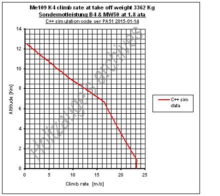
Pilum replied to KenobiOrder's topic in Bugs and Problems
These Me109K4 climb rates for 1.8 ata with B4 & MW50 are way too optimistic. Both with regards to historical data and also the C++ simulation figures I get (See attached figure). However, the Me109K4 is still in beta AFAIK and none of the other aircraft released by DCS so far have had such large deviations compared to historical data so I'm sure it's just a beta issue and that they will fix it before the final release.