Kurfürst
-
Posts
861 -
Joined
-
Last visited
-
Days Won
1
Content Type
Profiles
Forums
Events
Everything posted by Kurfürst
-

Does the engine die much faster with the new patch?
Kurfürst replied to taps's topic in DCS: Bf 109 K-4 Kurfürst
605 DB/DC had increased 30-min ratings: the previous 1,30 ata rating was increased to 1,45 (in march 1945 reduced to 1,40 due to B-4 fuel quality fluctuations, DC ratings were uneffected however). 1,35ata was the 30-min rating for the early DM engine, but we do not have that one in DCS. -
Which 109 was a better turning plane ? G14,6,10. K4 ?
Kurfürst replied to otto's topic in Military and Aviation
My bet would be on the G-14 at low altitudes, K-4 at high altitudes - though the fully boosted 2000 PS K-4 would be probably beat them all. -
Hummning, check out VEAOs projects in the forum, they have an ultimate version of the XIVe in the making. ;)
-
Slats deploying at high speed ?
Kurfürst replied to Dirty Rotten Flieger's topic in Bugs and Problems
Twist however decreases AoA and hence lift, thus to get the same lift you need higher AoA which results in more drag. Gaps of the slats might give some small rise in parasite drag but they are closed most of the time, so their effect on parasite drag is probably miniscule. And when they are open you are actually better off with them, since they energize the airflow which amounts to much less drag than a turbulant airflow in the same condition without them! -
Some opinion about maneuverability of Bf109K-4
Kurfürst replied to gomwolf's topic in DCS: Bf 109 K-4 Kurfürst
Out of curiousity, did anyone tested the best sustained turn time of the 109K in DCS? -
The arguement for it is not without merit. The B-17 was a result of a procurement for a very long range maritime bomber, not a heavy bomber. Nobody particularly wanted it to be a four engine one, Boeing just cut the corners and made it a four engine one. In bomber capabilties, however, the early ones were not that much different from the better medium bombers of the war. The limited internal bombload, which is often laid at the doors of the B-17 in comparison but its largely unfair since it was put to a task (strategic bombin) which it was not supposed to do originally.
-
Some opinion about maneuverability of Bf109K-4
Kurfürst replied to gomwolf's topic in DCS: Bf 109 K-4 Kurfürst
I wonder the exact reason behind rounding the wingtips on the 109F-K - was it for reduction of drag (like winglets on modern airliners)? -
Same for the P-47 I believe, there were also a 6 gun option.
-
yes!finally mighty wings with open beta!
Kurfürst replied to 9.JG27 DavidRed's topic in DCS: Bf 109 K-4 Kurfürst
Physics don't get effected by plane models. The ultimate g limit of about 10 g (not 7, that was the safe limit w/o the safety limit) is for one-axis acceleration, ie. a clean pullout. It can be much less when there is a yaw on, or if the ailerons are used at the same time, these will twist the structure due to asymmetric loading. AFAIK however, planes were not stressed for twisting damage, and combined forces can present you with forces the structure is not prepeared for, nevermind the more violent and self-inducing things like flutter oscillations which can be encountered at high speeds. Those will break any plane. The TAGL mentioned seems to be specific about the wingtips and yaw conditions, I suppose where there was some yaw effect it may exposed a much larger surface of the wingtips that they simply could not support, since they were not sized for such force vectors. I am sure they have worked on it, but there is no solution that will completely eliminate structural limits. AFAIK the persistent wing break bug on the 109K was caused by some hiccup with the wing fatigue model, that is, the plane may survived a 7 or 8 g pullout at the bending limit, but the damage and reduced load bearing capacity of the structure was recorded and subsequently less load could break your wings. The problem was apparently that this fatigue appeared abnormally quickly, or something like that. -
yes!finally mighty wings with open beta!
Kurfürst replied to 9.JG27 DavidRed's topic in DCS: Bf 109 K-4 Kurfürst
1. Rudder increases rolling ability of the aircraft and the 109 has a rather powerful rudder. Wheter full deflection could be made with the late type rudder with Flettner (which reduces control forces) is open to debate but I am yet to be convinced that "heavy, but not unpleasant" remark 2. Historically correct. See TAGL for dive instructions for 109F/early 109G on assymetric yawing stresses. Its also valid for all planes of course, but not all planes have similary powerful rudders. It also points that the rudder being well usable in dives: (2) Yawing in a dive leads to high one-sided wing stresses which, under certain circumstances, the wing tip cannot support. When a yawing condition is recognised the dive is to be broken off without exercising force. In a flying condition of yawing and turning at the same time correction must be made with the rudder and not the ailerons. The condition of wing tips is to be examined and checked with TAGL. Bf 109 Nos. 5/41 and 436/41. So with some special flight conditions (combination of yaw with other change in pich/roll?) yawing in dive will lead to structural failure. 3. Agreed. However that sensation is the physcal sensation of the real life pilot. A hand can excert about 20-30 kg sideways force for the ailerons, a bit more for the elevators, say 50-60 kg, but the legs can push 100-200 kg easily for the rudders. Try pushing you body weight in on a single leg for example. I find it very unlikely that with that much of force you would be in difficulty operating the rudder. Perhaps they'd be a bit more mushy in operation at high speed because of the larger forces, but very likely still very much deflectable. Then the question is, lacing any sorts of rudder force data, should we introduce an hoc "stiffness" factor which may well be a completely fictional aspect? -
Some opinion about maneuverability of Bf109K-4
Kurfürst replied to gomwolf's topic in DCS: Bf 109 K-4 Kurfürst
There is nothing wrong with the variation of flight test results, its just a consequence of mass production. I am just pointing out that the test you posted was apparantly for an exceptionally well built aircraft (or different measurement standards), mine was probably a worn or less well built example. The typical aircraft was probably somewhere between. -
Some opinion about maneuverability of Bf109K-4
Kurfürst replied to gomwolf's topic in DCS: Bf 109 K-4 Kurfürst
And then look at this real test. http://www.wwiiaircraftperformance.org/mustang/tk589.html 354 mph at SL at 67". Mustang flight test results are all over the place. -
yes!finally mighty wings with open beta!
Kurfürst replied to 9.JG27 DavidRed's topic in DCS: Bf 109 K-4 Kurfürst
Ok then model elevator stiffness for the P-51... because its also described 'heavier'. :doh: I suppose for the pilots used to the Spitfire everything bar the ailerons were heavier, because for some reason the ppl at supermarine always aimed at delicately light controls. And I presume it shouldn't, because..? Its still unclear wheter you want mushed control reaction (force effecting the time required to reach deflection) or limited control reaction (force too high to overcome). -
yes!finally mighty wings with open beta!
Kurfürst replied to 9.JG27 DavidRed's topic in DCS: Bf 109 K-4 Kurfürst
I don't think it was a deflection limiting factor, so like the (practically non-existent) elevator "stiffness" on the Spitfire or P-51, there isn't anything to model. Especially considering that (i) there is no source indicating such rudder stiffness, quite the contrary its either reported to be light or moderate (ii) considering the vastly larger muscle force of legs compared to human arm on the stick and the K's Flettner tabs on the rudder (iii) not being any advantage to fully deflect the rudder at high speeds anyway, which can be even dangerous. In short imho there was no stiffness to model in the first place and even if there was, there would be little point to model it. -
Yes, but lacking serious evidence, I still don't buy. Maybe there were odd examples, but that's just speculation - again none of the specs I have seen for the K-4 note that it was ever intended to fit anything but a 108. The K-2 may have been planned with the 151, but the G-10 effectively replaced the need to produce the K-2 in the end.
-
I have never seen it mentioned anywhere except in some secondary sources (Prien).
-
yes!finally mighty wings with open beta!
Kurfürst replied to 9.JG27 DavidRed's topic in DCS: Bf 109 K-4 Kurfürst
Nope. -
Bf-109 Elec. Propeller Pitch control, .. how it works?
Kurfürst replied to IIIJG52_Otto_'s topic in DCS: Bf 109 K-4 Kurfürst
Whatever the case being argued, I always enjoy reading these discussions very much. YoYo's very through knowledge of appearantly every engineering detail behind ('how stuff works') and his willingness to explain it is simply awesome! :) -
According to the GLC sheets (which gave proper weight breakdown) the fully equipped, loaded and fueled (incl. MW) weight was 3362 kg. The 3400 kg figure is I believe rounding up.
-
Probably so, but perhaps the difference is not that great, if you speak of XIV or a +18 IX. Wingloading is just half the story, what it effects (greatly) is drag in turns. Overall drag is also effected by parasite drag, which was much less on the K, and power, which was a lot more Where drag and power in turns equals each other, you have the best sustained turn rate - quite typically at 3-3,5 g. Now the Russians have tested a G-2 with gondies which weights about the same or perhaps less than a K-4, they measured a 22 sec for sustained turns at 1000 meter, which is about the same as a Fw 190 A or a P-51D perhaps. One would have to crunch some numbers what happens to that 22 sec turn if you add about 80 kg, chop off 25 km/h worth of drag and most importantly, add no less than 500 horsepower to the coctail... I suppose it goes down to about 20 sec, perhaps even 19 sec. It all changes with altitude, following the engine output curves but generally speaking K was just as good at high alt as it was down low. Agreed.
-
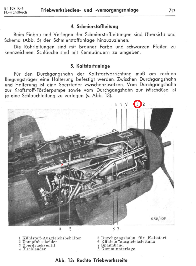
I just glanced over the manual, but it appears to be only on the right side, a small pipe connecting to the right coolant balance tank (Überdruckventil).

-
Cool with me, Sith.
-
The document describes the development of the Spitfire as well. The page you are showing does not seem to relate to the tested aircraft results, rather just some general specs table for various other Spitfire variants, Mark V and IX.
-
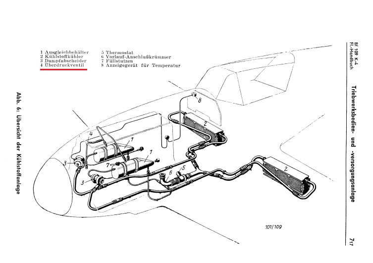
Can we have the coolant pressure relief valve operation, with GFX of glycol cloud when the engine is running too hot..? Description of its operation can be found in English in relation to a Black Six accident report, at http://www.aaib.gov.uk/cms_resources.cfm?file=/dft_avsafety_pdf_501760.pdf Engine cooling system description The powerplant in this aircraft wasa Daimler Benz 605A 12 cylinder inverted 'V' supercharged liquidcooled piston engine. Heat generated by this engine is dissipatedinto the slipstream from two radiators, one located beneath eachwing root towards the trailing edge. The cooling air flow iscontrolled by two hydraulic actuators which determine the positionof the intake lip and upper and lower radiator flaps associatedwith each radiator. These flaps are controlled by the rotaryselector valve, set by the pilot to one of four detented positions(Figure 3). Both radiator flaps move in association with thewing flaps. The valve settings are 'auf' (flaps fully open),'zu' (flaps fully closed), 'ruhe' (flaps hydraulically lockedat their current position) and 'autom'. It was found that itwas necessary to position the rotary selector handle from the'autom' legend by 16° in order to engage the detent. Thedifference between the 'as found' position and the 'detent' positionsof the selector can be seen at Figure 3. When the flaps are atthe closed position, and the wing flaps are retracted, the coolingflaps remain slightly apart, and maintain a minimum cooling flowthrough the radiators. The 'autom' setting provides for automaticmodulation of the flaps position under the influence of a thermostat. This is installed in the coolant outlet pipework from the engineand normally regulates the engine coolant temperature to around80°/85°C. At approximately 110°C, at low altitudes,the coolant may be expected to boil. The cooling system operatesat elevated pressure maintained by a pressure relief valve whichoperates at approximately 1 bar. Any outflow of coolantfrom this valve is piped so as to discharge immediately aheadof the exhaust stubs on the right side of the engine, where itimmediately vaporises, thereby indicating to the pilot in a directmanner that the engine has become too hot. Under these conditionsit is reported that vapour may enter the cockpit although thepilot was not aware of this. The design and orientation of thisrelief valve are such that positive g assists the valve to open. Engine temperature is indicated to the pilot on a dual functiongauge (Figure 4). This gauge normally indicates coolant temperature,unless the adjacent spring loaded button is pushed, whereuponoil temperature is displayed.
-
That, or that the full throttle heights in the test results that correspond to M66 / +18 boost. Besides AFAIK the Soviets only received Mk IXs with M66s (and a couple of Mk Vs). With M61 the FTHs would be much higher also. Neither it was possible for a +15 two staged spit to achieve climb rates in the order of 22-23 m/sec..