jj3
-
Posts
21 -
Joined
-
Last visited
-
Here are the files I've made up so far. There is a Samtec 24 pin IDE cable that I found at Mouser part #: 200-HCSD12D06001TP01 Mfr. part #: HCSD-12-D-06.00-01-T-P01 It comes as a "23" pin cable with a pin blocked, just remove the plastic pin and it's now a 24 pin cable. If I was to do this again, I'd make it a flexible cable instead. A10 Console CDU Boards.zip You will need an arduino MEGA, some long pin headers for that, and the pin connectors (green jobbies) if you want removable connections. Otherwise just solder in your wire. The LED schematic is for an external power regulated source, there is no restricting circuitry to limit current in any way.
-
Is this still in development? My iPad decided to test gravity onto a tile floor, so I’ve been reinstalling to a new device. Beta invite has been closed through TestFlight, and I don’t see it in the App Store.
-
DCS-Bios and a chunk of code from some other folks. One of the links I could find:
-
Negative, I should clarify. I will use the display module and mount that to he CDU backside, then connect that display module pins via wires/cable to the mega.
-
@obious I used https://jlcpcb.com/ for this, they have a giant parts warehouse for pick & place if needed. Boards were made within a week on their end and tested for connectivity, shipping was painful though. They have a simple PCB design software that connects to the fab plant, takes a bit to learn though. They are connected to https://lcsc.com for other electronic parts. Picking the parts order was fast, shipping time was slow. They also don't combine shipping between companies.
-
Apologies for the long delay, here’s the connections board that will connect to the keyboard pcb via standoffs. Has the arduino mega, rs485 board, power input, and moves the unused pins to the edge so they are easy to get to. This is designed to have a display module attached via a cable routed to the correct spot on the CDU board. I'll probably use long pin headers through the board for that purpose.

-
I started a build with custom PCB's, https://forums.eagle.ru/topic/251428-flights-cdu-panel/ I do have a couple extra sets, but I haven't had the chance to wire everything up and test it all yet.
-
Thank you @agrasyuk
-
By chance has anyone saved, or can explain the procedure Deadman describes way back on how to paint up the knobs, and mask them well? All the photos are gone.
-
Sweet, thank you gents! Learned a lot today, so it's a good day.
-
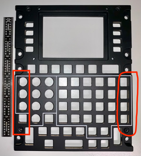
@Nikolas_A In the case of the CDU, it's not that simple. The highlighted buttons are where the rail is underneath for the DZUS. I'm guessing that's why it's raised up in the photo above - to allow clearance for the side buttons in th e panel.
-
Thank you @sharkfin61, that's the perfect angle!
-
sounds like an interesting mod idea to me. Then folks could use it or not at their discretion. No, I’m not a mod maker. +1 for at least having the chocks command like the other aircraft though. Cheers!
-
After a bit over 2 hours soldering, it's all wired up. I decided to make another board to hold the mega, rs485, and break out for the screen and unused inputs. I was told A10's have the CDU raised up, so it's not sitting directly on the rails. Haven't seen a photo myself of this setup, but it's an idea to get all the right/left edge buttons to fit easily. Not overly thrilled with the refresh rate on the screen, I used code and examples from:
-
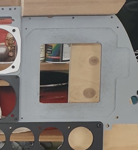
Are those MFD cutouts that are modified to fit the cougars removable? If not, since you are planning to upgrade in the future you may want to make those removable now before you have too much installed.