yoreh
-
Posts
51 -
Joined
-
Last visited
Content Type
Profiles
Forums
Events
Everything posted by yoreh
-
DCS-BIOS - How to send a freuency value directly to a UHF radio?
yoreh replied to yoreh's topic in Home Cockpits
For the hardware You'll need an Arduino. if you want to go with Hans method (using port registers), than you'll have to go with the Arduino Mega. You'll also need some wires and soldering equipment. As for the software part, i'm gonna post the code here in the near future as soon as i finished with all the switches and knobs on this radio. i can also provide the truth tables for the selectors but you'll have to check them with your selectors to make sure they are the same. Cheers, Yoreh -
DCS-BIOS - How to send a freuency value directly to a UHF radio?
yoreh replied to yoreh's topic in Home Cockpits
success!! Thanks Hans. could not have done it without your help :) and finaly, after long struggle with the code... it's working!!! still need to hook up all the switches but this should be pretty straight forward. when everythig will be done i'll post the code here. Cheers, Yoreh -
Thank you so much guys!! Yeah i know, but i figured i need a space for the Radar Altimeter so i'm gonna place it on this placard anyway...
-
Some work on the cyclic gimbal. Yesterday i managed to make some parts for the rest of the gimbal mechanism. here you can see a base plate (steel), upper plate (thin aluminum), some bearings, the bearings brackets (steel), some 12mm rod, and the already made gimbal part. i drilled the base plate in the center (63mm), and drilled and tapped the maouting holes. then tack-welded the brackets to place complete gimbal from below and from above. still to do - connect the rotary motion sensors to the x/y axes. - Design and build a magnetic force trim system. Cheers, Yoreh
-
DCS-BIOS - How to send a freuency value directly to a UHF radio?
yoreh replied to yoreh's topic in Home Cockpits
Thanks. -
DCS-BIOS - How to send a freuency value directly to a UHF radio?
yoreh replied to yoreh's topic in Home Cockpits
So i decided to adopt Hans code with the port registers and actually it worked out pretty good, thank you very much Hans!! . i am now in a position that i can present the frequency on the serial monitor / 7 segment module. Here is a small video to demostrate that. As for transfering the data to DCS Huey... i understand the logic, but still unable to translate that into Arduino code. I will try to get in touch with Ian to solve this issue. PS. Anybody know how to post videos directly inside the post? -
Toda!!
-
Here's a quick update. I have installed a floor plate for the pedals area. and added a damper to get more "hydraulic" motion than mechanic. then i noticed that even on the lowest setpoint of the damper, i still get lot of resistance from the pedals. something is wrong. the problem was the threaded rod that holds the "T" bar in place. this bar is pressed between two nuts and washers and created lots of resistance. So i decided to change the rod to a round one with bearings. i took it all apart and welded the rod to the "T" bar. at this point i also welded the M8 bolts to the bar. i then put everything back to place with the help of some surface base bearings (three of them). Now, the pedals runs smoothly as they supposed to. the feel is very hydraulic and precice. with that out of the way, i started on my cyclic rod. i don't have a tube bender in my shop so the best solution for me is to use scrap tubing that al is already bent. here is my donor - i salvaged the parts i need and welded them together - at the top i welded an 1/2" threaded coupler . this will receice the grip in the future the rod is significantly long right now. it will be shotened down to size eventually. And finaly i started working on my gimbal for the cyclic. it is a very simple design consist of two square tubing (outer=70mm, inner=30mm), some bearings and 12mm round rod. here it is so far - my idea is to mount it beneath the floor level and create a force trim magnetic system for it. Cheers, Yoreh
-
Sure. first, install an app called "Spacedesk" on your phone and pc. this will define your phone screen as another pc monitor. then use Ikarus to export those warning lights to this monitor. it's simple!! Here is a link to my graphics if you want to use it. Thanks. the collective is DIY. it has started as a child scooter front end. the long tube is the one that holds the handlebar, and the short tube (my twist-grip) is the part that was connected to the scooter chassis. for the electronics, just a bunch of toggles, push-button, and a digital joystick, all packed up in an aluminum junction box. the twist-grip is connected to a potentiometer, and the collective up-down is done with a hall-effect sensor and a magnet. all the inputs (analog and digital) are currently connected to a leo-bondar joystick interface board. Cheers, Yoreh.
-
DCS-BIOS - How to send a freuency value directly to a UHF radio?
yoreh replied to yoreh's topic in Home Cockpits
Hans, that is amazing! this is exactly my situation and your solution looks very elegant!! i will take a closer look at your code and try to adopt it to my setup. Thank you very much for pointing me in the right direction. :thumbup: -
DCS-BIOS - How to send a freuency value directly to a UHF radio?
yoreh replied to yoreh's topic in Home Cockpits
Thank you Sir! that will surly add some effect... Thank you Ian, can you explain a bit on this exported frequncy data? Marry cristmas to you all -
DCS-BIOS - How to send a freuency value directly to a UHF radio?
yoreh replied to yoreh's topic in Home Cockpits
Hi i'm currently working on an Arduino sketch to load the frequncy values from the physical UHF radio. at this point my sketch presents a decimal number for each selector, that is the same number showed on the pysical radio display. now, i need to figure out how to send this data to dcs via DCS-BIOS. i have looked in the control reference and only saw "inc/dec" commands related to those selectors... didn't find any way to send a specific selector positions. Any help would be appreciated, Yoreh. -
DCS-BIOS - How to send a freuency value directly to a UHF radio?
yoreh replied to yoreh's topic in Home Cockpits
Thank you Ian, i'll PM you when i'll wire it up. -
Hello, i have a UHF radio witch i would like to use in my cockpit. to my understanding it's a fairly "stupid" device, witch sends a binary representation of a given frequency. would it be possible to take this binary string and send it somehow to the same device on the virtual cockpit, thus keep sync with the hardware radio and the software radio? This is the unit - Regards, Yoreh
-
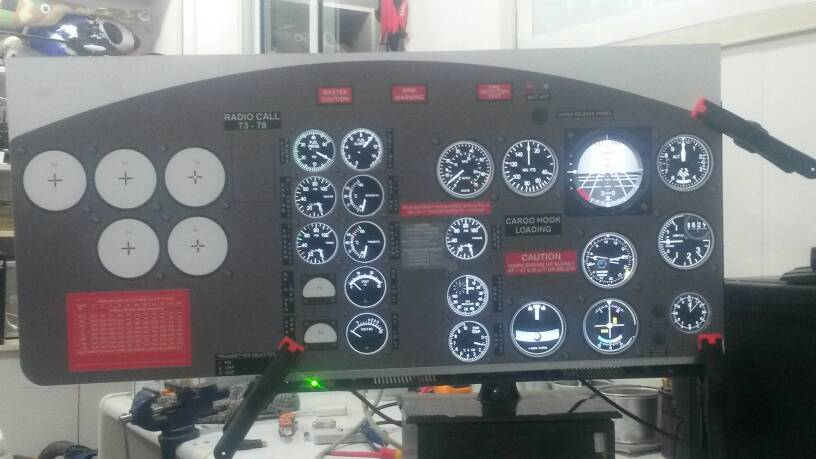
Thanks Alot guys! Quick update. work on the instrument panel continues. i added the covers for the smaller gauges, and also added some encoders on the radio compass, CDI, and the Altimeter. the yellow brackets are temperary. Cutting the holes for the encoders: Temperary brackets: The back of the encoder is flush with the back of the panel. that's important as thw lcd panel is right behind... The isntrument panel with the new covers and encoders installed: there's still a lot of work to be done... Cheers Yoreh
-
i'm out of co2 for my welder so for the meanwhile i decided to create the istruments covers. i started by cutting squares of transparent PVC and some slices of PVC pipe: i then guled the pipe to the square using PVC cement and primer, and drilled holes in the corners: after the gule dried up i masked the the inner circle and the back with masking tape, then painted it mat black: after the paint was dry i removed the masking on the back and drilled the holes on the instrument panel. i numbered the covers and the thier loctions because even if they are the same size, there could be small ofset of the holes.. i then installed the covers on the panel using 4mm alen bolts (cone head) with cuped nuts: i coverd the bolt heads with electrical tape to make sure they will not come in contact with the LCD panel inner masking removed: Final resault: Ofcourse this is only one size of covers, there are more covers to make. Cheers, Yoreh.
-
quick update - Glareshield added, and the pedals are done (no electronics yet) i made some small changes to the design, like moving the instrument panel and console 10cm forward. as for the pedals, the original space between them was 20 cm, i changed it to 14cm. next on the list is to mount the overhead panel and then start working on the cyclic and collective. cheers Yoreh
-
Hi, Here is my cockpit project witch started some four years ago. since then i've been on and off on this build. it started as a small trainer (cyclic, collective, pedals) and now it's evolving to be a full cockpit with panels,buttons, dails, dashboard and so on... in order to export the instruments i will be using the ikarus software. for the analog input (axis) i will be using a joystick board, and for all the buttons and staff i will be using Arduino and DCS-BIOS. Here are some pictures of the small trainer, as you can see it's only analog axis: new collective head: new cyclic grip (B8 style...) An old smartphone as a caution light panel: Here are some pictures of the current situation. you can follow the the project from the begining here on HoverControl. Cheers, Yoreh
-
Thank you Ian, you sorted up some mess in my head. did some testing today with an Arduino UNO. my first DCS-BIOS project would probably be the UH-1 caution panel. so i hooked up some leds, they all worked fine, setup was nice and easy. then i tried to operate the test/reset switch - that did not worked. the bright/dimm switch didn't work either. i tested the hardwre switches on some other switches in the cockpit (gov, ldg lights...)- they worked fine. So i observed those two switches on the interactive control reference. when i flip the switch in the virtual cockpit, it will change it's state in the control reference. when i flip the hardware switch nothing happens. switch conected to GND on common lead, pin 5 and 6 as the inputs. my line of code for the switch looks like that: DcsBios::Switch3Pos clpResetTestSw("CLP_RESET_TEST_SW", 5, 6); i wonder what am i doing wrong? Cheers, Yoreh
-
Hi, i'm currently looking for an altenetive solution for hooking up my panels to DCS, so DCS -BIOS looks very promissing. How many arduino boards can i conncet and operate wit DCS-BIOS? What would be the best board to use? Yoreh.
-
Hi and thank you for your efforts. I alrady use ikarus and it's anazing! My arcaze card (with led and display cards) arrvied yesterday so i tryed to play with it .i could make a led turn on directly form The main card, but not from the extention card. Tried to create a switch in d.a.c, no success yet. Is there any manual explaining how to connect the arcaze module to the extentions? (Leds, disolays) Thanks alot guys, great software. Sent from my LG-H815 using Tapatalk

-
Hawgtouch - huey panels?
yoreh replied to Raven_Morpheus's topic in PC Hardware and Related Software
Oh, i see. thanks again. -
Hawgtouch - huey panels?
yoreh replied to Raven_Morpheus's topic in PC Hardware and Related Software
Thank you very much. this is awsome!! I have tried to move the huey instrument to a second monitor(ID 2), following your instructions in the quick start guide. (edited the HT UH-1H all.xml) but for some reason it keeps opening up on my main monitor (ID 1). any help would be great. -
HawgTouch - Free Panels & Gauges for A-10C
yoreh replied to ClearDark's topic in PC Hardware and Related Software
Is there a gauges pack available for the uh-1 huey? -
Wow those are great news for me :). I've been looking a glass cockpit software for the uh-1 for a long time. when version 1.6 will come out i will finally have a working instrument panel... can't wait to give it a try!! Any news about the release date? Thanks alot for your efforts. :thumbup: