nighthawk2174
-
Posts
1517 -
Joined
-
Last visited
Recent Profile Visitors
11684 profile views


-
Каковы размеры решетчатых стабилизаторов на P-77?
-
Specific impulse wise HTPB is probably in the range of 242-248. There are patents from the late 90's early 2000's which change up the blend to get it higher but these would not be relevant for the 120B/C. 1498409585215997771-06238499 US6238499B1 - Solid rocket propellant - Google Patents
-
So with it reacquiring why. Does the R27 through its speed gate open if the target is lost? More importantly though chaff should not be impacting a speed gate this bad it should be minimal. Speed gates are often only 10-15kts wide and chaff will fall out of that well before they bloom to an RCS that could be useful. Chaff slows down at 700-1200m/s if memory serves me right and bloom time is 2 or so sec to go to its full RCS. Even near the beam the drop off in speed is such that it should fall out of the speed gate in a fraction of a second.
-
With such methods its best to do a lower and upper estimate which will give you a reasonable range of results. It can be difficult to get exact measurements from photos but depending on how accurate you want to be they can suffice for a reasonable estimate.
-
Do you have the original documents these fin diagrams come from?
-
That'd be good enough considering the limited nature of information.
-
Concerning the motor shape is there a diagram that exists your work is matched too? Do we know the propellant type as well?
-
A few questions regarding the R77 - What are the dimentions of the lattice fins and chord profile? -How much is known about the motor? -How much is known about the radar seeker?
-
I don't think there is a simple method by wich you could calculate it except at very low machs. Shock interactions basically make it so that you need CFD or wind tunnels to do this. You could probably estimate with a drag build up method but it'd have large error margins on it.
-
L/D of ~2.4 which is reasonable and the shock angles are reasonable close for M2.5 at 5deg. The original paper I posted was at ~2.15 L/D and Russian document was ~2.2. Also are these body axis force coefficients or wind referenced?
-
https://ntrs.nasa.gov/api/citations/20040110952/downloads/20040110952.pdf A NASA paper I remembered seeing a few years back may be worth a look.
-
The plot has mach number listed with associated plot colors. M2.0 would be a light green to green'ish teal color. While upstream appears to be a light-medium blue instead. If upstream is M2.0 based on the expansion fans angular width i'd expect a much higher post fan mach. M2.5 - M 2.8 depending on how you measure out the fan angular width. But it itself appears to also be awfully close to M2?
-
Is this plot for those condtions you listed?
-
Probably being lost in translation what i'm saying is that the chart you posted lines up with what i'd expect to be the points where you get direct interaction, shock reflections directly off the opposite fin. However this does not preclude the main shocks hitting and reflection off each other (which will still chock flow) while still within a chord length of the tip of the lattice. Shocks off the lattice will nearly follow the oblique shock tables for thin plates. The angle at which the shocks will only interact with each other (as in shock off shock reflection) more then a chord length from the lattice tip can be calculated. This is why flow is still chocked even up to M2.5 not as bad as with all the shock reflections at a lower mach such as M1.5 but it is why the L/D still remains poor except at very high machs 4.0+. Ok
-
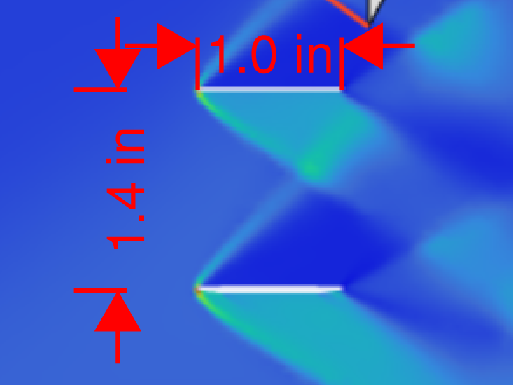
Yes I do the tradeoffs are that by increasing tbar you decrease drag but also decrease lift and dynamic stability. Essentially larger boxes makes it have lower L/D with worse stability, but the sooner you stop getting shock reflections interfering with each other. The chart you posted will be the point where the shock angle is such that you stop getting shock reflections for various tbar's and aoas. The shocks will still interact inside the lattice at least until a much higher mach usally M4+. The pressure coeficent drawings fin outline is making it difficult to tell but the shocks in that example are not interacting with the other plate of the lattice just with the other sock/expansion fan which is to be expected for that mach and angle. null Also from your images tbar appears to be closer to 1.4, scaled such that chord = 1". Doc I linked with the pressure coeficent iso's is ~1.48 inner to inner surface.