

nighthawk2174
-
Posts
1514 -
Joined
-
Last visited
Content Type
Profiles
Forums
Events
Posts posted by nighthawk2174
-
-
On 7/21/2025 at 6:35 AM, tavarish palkovnik said:
I was questioning why and how comes there is no yet on internet drag function for R-77. Really it is not easy to calculate such configuration, actually I'm giving up of it. Simply I don't have enough literature to make some reasonable, at least approximative calculation. All other rockets with normal fins can be quite easily calculated and results were not so bad, actually where had valid data to compare, not bad at all.
There are several paper works but mostly they have focus on drag of individual fin, and I'm interested in full assembly. I was mentioning base pressure, one of the easiest parts of total drag calculation, but here with grid fins I just stuck and don't know how to proceed. And like said already, I'm expecting this part together with pressure on fins to be significantly higher then what is case with classic fins or wings whatever is in aft zone

Few such aft section surfaces, Phoenix, Sidewinder and Sparrow
For all these configurations base pressure can be easily calculated, and this ''c'' number (ratio between wing thickness and aerodynamic chord) is for these samples approximately 0,036 ; 0,046 and 0,09.
What grid fins make on body base I have no idea ...
Do you have the original documents these fin diagrams come from?
-
On 7/12/2025 at 1:15 PM, tavarish palkovnik said:
If I say this is with 95-98% precision reconstructed motor, would it be enough?This is after all, just one more motor layout in line which I shared here, beyond others for which you will hardly find something on internet. But everything can be found, one way or other
That'd be good enough considering the limited nature of information.
-
1 hour ago, tavarish palkovnik said:
Motor is clear more or less
Now I can just wait @MA_VMF to finish Cx and Cy functions to make пуск with more accurate data. Hope it will be done in this lifetime

Until waiting, one bold prediction for rocket’s passive Cx at 1,1M AoA=0 … 1,4 with body cross section as reference area. Cy something like 0,6 1/deg
Concerning the motor shape is there a diagram that exists your work is matched too? Do we know the propellant type as well?
-
A few questions regarding the R77
- What are the dimentions of the lattice fins and chord profile?
-How much is known about the motor?
-How much is known about the radar seeker? -
2 hours ago, tavarish palkovnik said:
C=Relative Wing Profile Thickness=Ratio of Greatest Wing Thickness to Chord
When fins are in classic form I understand and know how to calculate base pressure drag... but how to calculate it when having grid fins !? What should be used for thickness, thickness of just one layer in grid ?
I don't think there is a simple method by wich you could calculate it except at very low machs. Shock interactions basically make it so that you need CFD or wind tunnels to do this. You could probably estimate with a drag build up method but it'd have large error margins on it.
-
2 hours ago, MA_VMF said:
Применена другая под программа и другой метод условия М=2.5 АоА=5.Отсутствует сгущение сетки на ударных волнах
nullnull
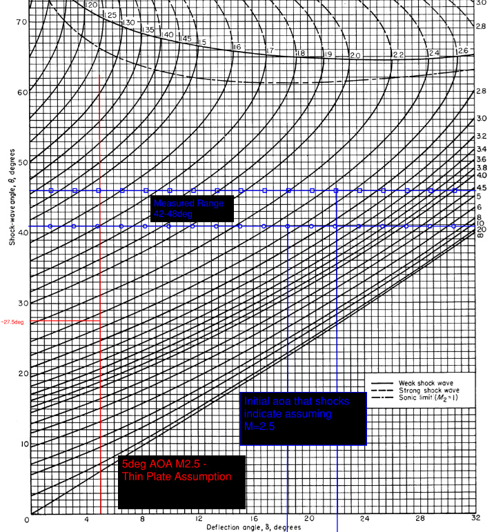
L/D of ~2.4 which is reasonable and the shock angles are reasonable close for M2.5 at 5deg. The original paper I posted was at ~2.15 L/D and Russian document was ~2.2.
Also are these body axis force coefficients or wind referenced?
-
https://ntrs.nasa.gov/api/citations/20040110952/downloads/20040110952.pdf
A NASA paper I remembered seeing a few years back may be worth a look.-
 1
1
-
-
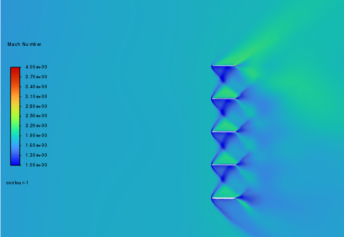
9 minutes ago, MA_VMF said:
I didn't understand the question
The plot has mach number listed with associated plot colors. M2.0 would be a light green to green'ish teal color. While upstream appears to be a light-medium blue instead. If upstream is M2.0 based on the expansion fans angular width i'd expect a much higher post fan mach. M2.5 - M 2.8 depending on how you measure out the fan angular width. But it itself appears to also be awfully close to M2?
-
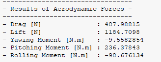
30 minutes ago, MA_VMF said:
nullMach 2 AoA=5 Drag=345.34N Lift=1822.59N
Is this plot for those condtions you listed?
-
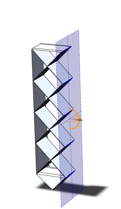
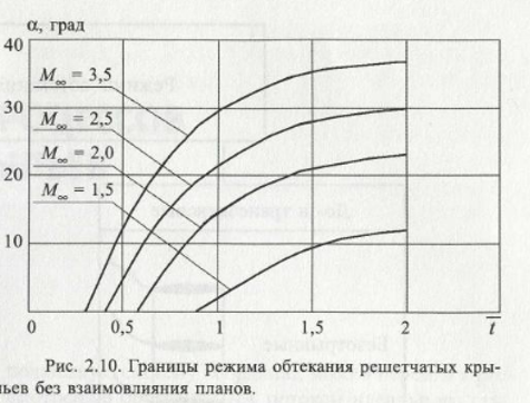
12 minutes ago, MA_VMF said:
This is a diagram showing the relative pitch of the grating and the angle of attack. The plans will not interact with each other
Probably being lost in translation what i'm saying is that the chart you posted lines up with what i'd expect to be the points where you get direct interaction, shock reflections directly off the opposite fin. However this does not preclude the main shocks hitting and reflection off each other (which will still chock flow) while still within a chord length of the tip of the lattice. Shocks off the lattice will nearly follow the oblique shock tables for thin plates. The angle at which the shocks will only interact with each other (as in shock off shock reflection) more then a chord length from the lattice tip can be calculated. This is why flow is still chocked even up to M2.5 not as bad as with all the shock reflections at a lower mach such as M1.5 but it is why the L/D still remains poor except at very high machs 4.0+.
12 minutes ago, MA_VMF said:nullThis is the plane of symmetry
Ok
-
9 hours ago, MA_VMF said:
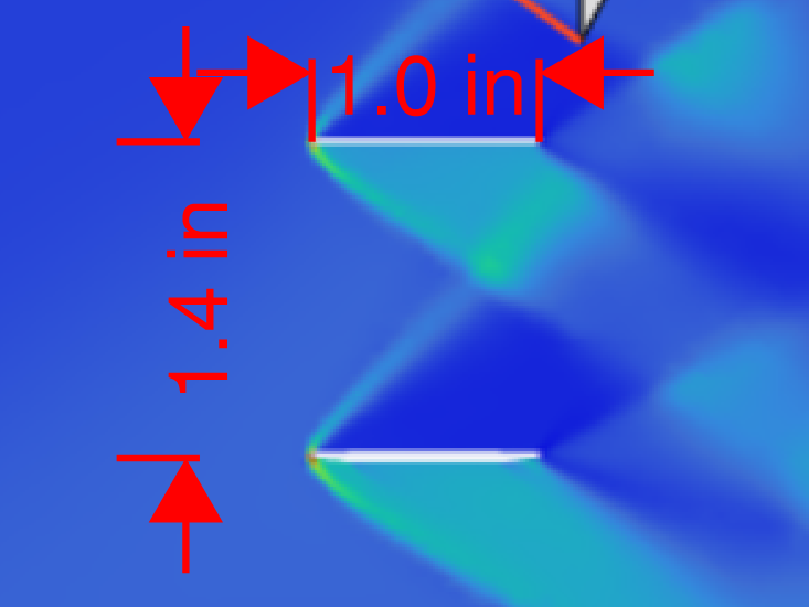
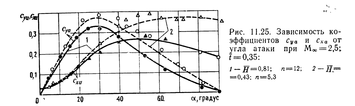
Do you even understand what grids exist? Different t_bar, H_bar , n grid in my calculations t_bar=1, H_bar=0.5
nulldespite the fact that there is already a mutual influence of plans in your drawing, although according to the schedule. At a speed of 2.5M, this should not be the case.
Yes I do the tradeoffs are that by increasing tbar you decrease drag but also decrease lift and dynamic stability. Essentially larger boxes makes it have lower L/D with worse stability, but the sooner you stop getting shock reflections interfering with each other. The chart you posted will be the point where the shock angle is such that you stop getting shock reflections for various tbar's and aoas. The shocks will still interact inside the lattice at least until a much higher mach usally M4+.
The pressure coeficent drawings fin outline is making it difficult to tell but the shocks in that example are not interacting with the other plate of the lattice just with the other sock/expansion fan which is to be expected for that mach and angle.
null
Also from your images tbar appears to be closer to 1.4, scaled such that chord = 1". Doc I linked with the pressure coeficent iso's is ~1.48 inner to inner surface. -
10 minutes ago, MA_VMF said:
I don't care what you've made up for yourself here. Once again, the conditions 2.5M and 5 AoA were set in the program. The fact that something doesn't match is your problem.
I haven’t made anything up; it is up to you to disprove what I’ve presented. You’ve provided no definitive proof to back the numeric results you listed. Said results don’t align with a substantial amount of wind tunnel and CFD data from NATO, US Army, and academic sources, including your own Russian sources that you posted earlier. I’ve studied lattices at a high level in university and have conducted my own CFD research on them. The numeric results you presented earlier simply don’t align with well-known data points from multiple reputable sources.
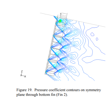
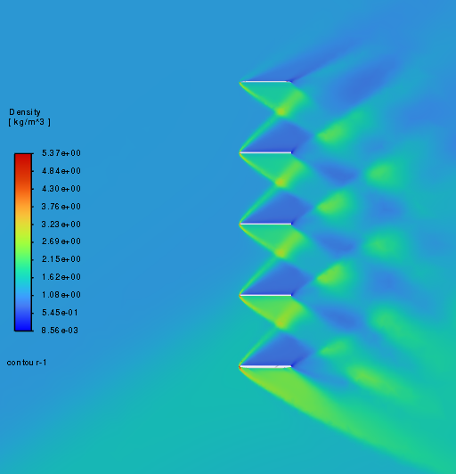
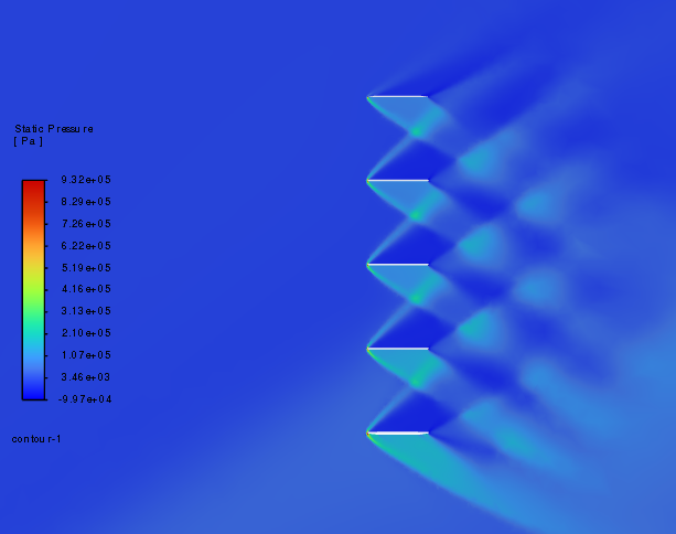
The static pressure profile you posted matches nearly the pressure profile from the below report which is at M2.5 and 20deg of aoa. The expansion fan on the leward side of the lattice and the shock on the windward side match the above. Indicating to me the CFD results you posted are almost ceratinly from a higher angle of attack then claimed.
CFD_analysis_of_grid_fins_for_maneuverin.pdf-
1
-
-
52 minutes ago, MA_VMF said:
L- near 2kN
D-near 420-430N
Only half of the steering wheel was used
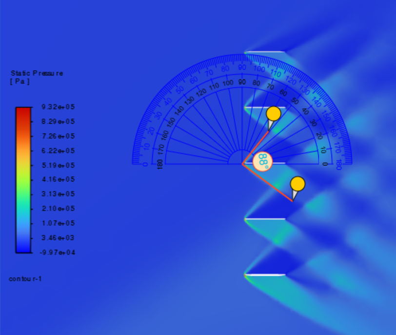
This data your presenting is not lining up, not even with data you posted earlier. Do you have a screenshot of the numerical readouts or is this just what was told to you? You said that this data was for M2.5 5deg aoa I can't imagine that the fins halfway deflection point is only 5deg. Looking at the shocks if this is at M2.5 the angle the shocks are at would indicate a deflection of closer to 20deg not 5deg.
null
We also have the CD and CY values you posted earlier for the M2.5 case:null
L/D at 5deg is 2.2 and at 20deg is 2. From the original study I posted at 5deg its Cy=0.25 and Cx=0.12 for a L/D of ~2.1.
I don't have ref area used in the numbers you posted but assuming that the 2Kn of lift is right - sea level + STP - then drag using the coeficents provided would be 906N of drag not 420|430N.
-
49 minutes ago, MA_VMF said:
3D
Gotcha did you run the CFD you posted, if so you have the numeric results? Also tbh i'm suspicous of those numbers as that is rather quite high and doesn't line up with the graphs you posted or the wind tunnel results I posted.
-
23 minutes ago, MA_VMF said:
Mach=2.5, AoA=5
nullL/D-4.5
2D only flow?
-
2 hours ago, okopanja said:
Still munching over the document you sent, but wanted to ask why were they so concerned about roll stability? E.g. how does it influence maneuverability and drag when it actually flies (no wind tunnel or simulation)?
E.g. the use cases for these missiles and guidance configuration look different, is the controlling function achieved with rear fins or canards in front?
Roll stability is important in that while manuvering if you are unstable in roll small pertubations can induce roll oscilations which you have to counteract with your control system. You can get long term periodic oscilations which are highly undesirable such as dutch roll if you are lacking roll stability. This can increase miss distances or reduce the efficency of the control system in general. For the army study this would be critical for reducing miss distances of guided muntions like glmrs.
For the army document the point was more so to analize performance between nose control canards and tail control lattice fins. -
1 hour ago, MA_VMF said:
AoA=20, L/D=2.5
Could you define a few of the other variables listed here such as t_bar/H_bar/m/n (where _bar just indicates it has a bar over it)
null
Yes and in the document I posted, the original one, they get ~2.4-2.5 L/D. The NAO wind tunnel paper with a slightly different gridfin design gets a hair over 3.3 L/D for M4.0 but for the fin only no body.
-
5 hours ago, MA_VMF said:
The research you're showing is complete nonsense
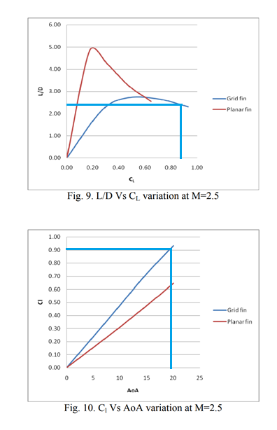
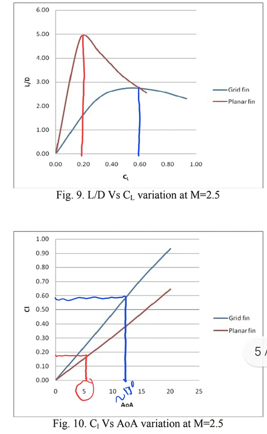
Yeah right, its up to you to prove the supersonic wind tunnel data in the following reports, which align with the one with the charts, are nonsnese. Grid fins experience more drag per unit of lift across most of their range especially at lower angles making the L/D much worse. Yes they produce more lift per unit of aoa, with less hinge moment, but at the cost of substantially more drag across their entire range. Hence why their not everywhere on air-to-air missiles.
ADA509444.pdf -
1 hour ago, MA_VMF said:
by Aoa=0 L=0;
According to the presented work, AoA <= 1 degree
Yes hence my confusion, your description of Kmax doesn't make much sense
And as described above for a moderate lifting load aoa difference is a few degrees.
-
5 minutes ago, MA_VMF said:
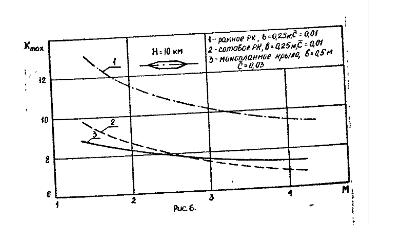
Kmax=L/Dmin . This is the ratio at which the lifting force is greater than the drag at a certain angle of attack.
Do you have the page which defines this value what you say here is confusing. L/Dmin is a very atypical expression to be used to analyze L/D ratios. As minimum drag will occur at Cd_aoa=0 and even more so if you mean minimum Lift over drag? And per your description this would describe the point where L/D>1.0?
I should also note based on the studies i've listed peak L/D efficency for the planar fins occur in the 3-6deg range. While lattice's are much higher often double this. -
1 hour ago, MA_VMF said:
Complete nonsense
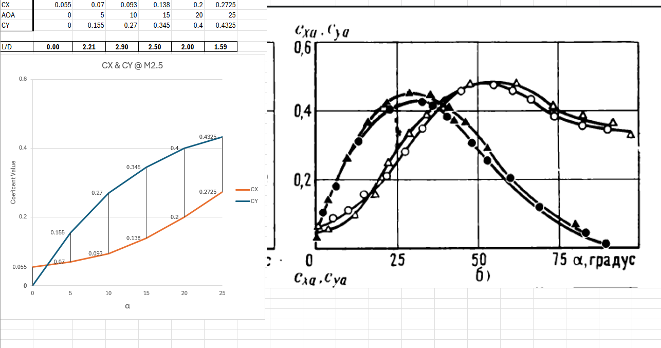
As we can see, the honeycomb design surpasses the monoplane fin to speeds of 2.5M.
L/D
null
Can you post the definition of Kmakc.
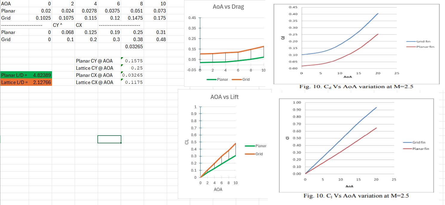
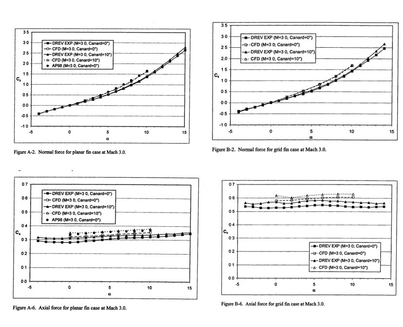
Another study to prove my point; data is from the US army supersonic wind tunnel with the reference area being idential between the two fins. Appears to be a study of using GMLRS body as a base with a planar and grid fin design. Study utilized CFD and supersonic wind tunnel testing and data. DREV is data from the wind tunnel.null
nullOnce again in this study a suboptimal design was used for the planar fin as it was just a rectangle with a double wedge chord shape. Not to mention it was extremly large.
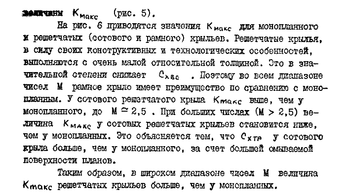
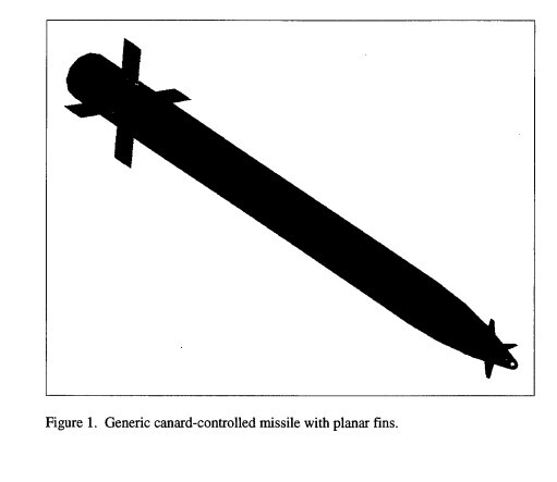
nullNumerical Investigation of Aerodynamics of Canard-Controlled Missile Using Planar and Grid Tail Fins. Part 1. Supersonic Flow -
On 7/5/2025 at 11:04 AM, okopanja said:
This might be too large and not very manouverable missile.
The paper nighthawk reference above is missing some important information, but most importantly makes some assumtpions on deflection angles.
Is it known what is the minimal deflection angle for e.g. minimal, medium and large corrections?
E.g. I would expect that deflection angles of traditional fins is larget than for grid fins, due to lower efficiency.
ADA509444.pdf Is a publically availble doc that has data up to M5.0 with more information, its results agree with the one I posted and is a source of wind tunnel data used by other reports.
What assumptions on deflection angles did it make that you are questioning?
Traditional fins will need larger deflections but at the same time their far more efficent with those deflections and have less 0 aoa drag. The biggest thing is the reduction in hinge moment per unit of aoa you want to get too, that is where the lattice has its largest advantage over a planar fin.
Just as an example lets say the missile needs to generate 300 lbs of lift per fin at M2.5 for whatever manuver it will be doing at that moment (I assumed 1000ft at STP for aero values). This would be what i'd probably clasify a "light-medium" correction considering you'd get thousands of lbs of angular force from all 4 fins. Using the data in the first report to generate 300lbs of lift the lattice fin will be at ~0.7-1.1deg aoa and the planar at ~3.8-4.2deg. At those angles the gridfin will generate nearly 15x the drag (60lbs vs 805lbs) or a L/D of 5.0 vs 0.38. Keep in mind this is also with a very suboptimal planar fin design used in the study. This drag penatly is why these types of fins are not in use for A/A missiles anymore. They make a lot more sense on ballistic missiles or bombs. Where the low hinge moments are very usefull and the drag penalty not as big a concern. In the paper I listed newer shapes of the lattice that were tested can cut the drag from 25-40% depending on mach and exact shape but the R77's fins are not one of these and even then planar fins still have better L/D. -
4 hours ago, MA_VMF said:
the advantage of the lattice is that it can be made smaller than a monoplane wing, while maintaining the same torque as a monoplane fin
Yes however at the cost of drag especially in the M0.7-M2.5 region. Ultimantly thrust vectoring is a far more appealing solution without really any downsides apart from complexity.
3 hours ago, okopanja said:Not sure why so much discussion on grid fines, especially in sub-sonic and transsionic range:
1. Launch platform can accelerate beyond transsonic range
2. majority of DCS missiles are between 2-3 Mach when they hit, which means the aircraft and missiles are most of the time in super sonic range.
Therefore what matters is actual performance in super sonic range.
1 - It can but often at the cost of high fuel consumption.
2 - True but chocked flow still persist even past the transonic its not until the shocks are at a low enough angle they do not interact till well aft of the lattice that flow becomes unchocked.
3 - Even then you will generally still have more drag when comparing similarly sized fins, based on actual dimensions not reference area, due to higher area. Even at higher mach regimes their drag coefficients do leave something to be desired when compared to monoplane.-
1
-
-
3 hours ago, MA_VMF said:
You need to compare two rudders of the same area. This study is complete nonsense
No this study is perfecly valid you're just coping. The study is practical in that it compares two similarly sized fins. If you were to make the monoplane fin have the same reference area as the lattice it would be impractically large. Even then the advantages of the monoplane in L/D and static stability would still persist.
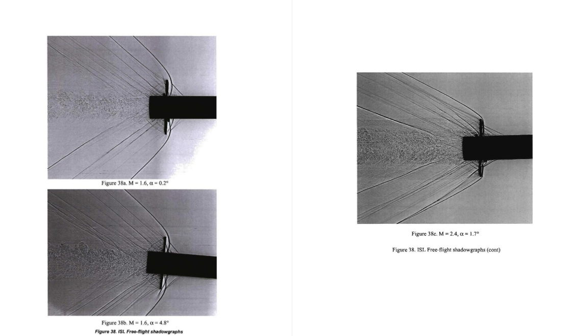
Just fundamentally the lattice will have higher drag then a similarly sized monoplane fin due to shock interactions especially at lower mach numbers. This persists up to ~M3.5+ when the shock interactions occur aft of the lattice instead of inside the lattice cells. There is no getting around this whether or not your comparing two similarly sized fins or two that have the same reference area. Below the blunt shock ahead of the lattice is a clear indication of chocked flow and is why there is a dramatic increase in drag coefficent.
NOTE the above is NOT my work I just coppied it from another forum where this exact same disscusion happened. You can calculate this point yourself if you want just lookup the oblique shock tables or follow this: 19930091059.pdf
These studies help prove my point I wish I still had access as I did a few years ago but if your willing to pay they prove my point:
Subsonic/transonic free-flight tests of a generic missile with grid fins | Aerospace Sciences Meetings
Subsonic Flow CFD Investigation of Canard-Controlled Missile with Planar and Grid Fins | Aerospace Sciences Meetings
.png.d6a7cbb29db434baed593415e9aad5b1.png)
.png.04c62fd69572c96365f7d3453c58f9ce.png)
.png.6db529c73f895c5e9d0cff279385ea1f.png)
.png.15c92fc2522bf859ffbf18d5a4364328.png)
.png.4c7a3ba7ef99b56b07672ecbecd83603.png)

Ракеты в DCS
in DCS World
Posted
With such methods its best to do a lower and upper estimate which will give you a reasonable range of results. It can be difficult to get exact measurements from photos but depending on how accurate you want to be they can suffice for a reasonable estimate.