

nighthawk2174
-
Posts
1514 -
Joined
-
Last visited
Content Type
Profiles
Forums
Events
Posts posted by nighthawk2174
-
-
On 5/19/2025 at 11:10 AM, tavarish palkovnik said:
@MA_VMF
Will you give some words about these results. Grid fin obviously and you showed us dynamic pressure values. But this pressure is actually the easiest part of these calculations, simply density * velocity^2 * 1/2 … 1,225*680^2*1/2=283220 Pa
To me and for most others I guess, all these CFD modelings are “gold” digging where “gold” are Cx and Cy coefficients in function of Mach. When having these coefficients everything else is just piece of cake. So how you find those coefficients? I guess software gives you drag force and from that Cx coefficients just drop out.So why and what for dynamic pressure?
Just from curiosity, how long it takes, with some reasonable calculation grid, to get drag forces on let’s say 10 different Mach numbers at same altitude? Hours or days?Generally, what takes the most time, making 3D model, or defining initial conditions or simply time computer needs to process data?
By the way, R-33, is it finished

I really don’t have clue how long it could take for one rocket to get ballistic data from software. Yesterday, boring Sunday afternoon, I processed on rocket and let’s say in two and half hours I got Cx, Cy and roughly moment situations to define static stabilities of rocket depending of altitude, velocity and angle of attack
Maybe I’m just wrong and taking all that very simplified, but I question myself, why internet is not already filled with mostly all, if not all, rockets processed
Of course others are also welcome to share thoughts
Dynamic pressure is usefull for viewing shocks as the pressure drop post shock is rather quite easy to see. The CFD results point to why lattice fins tend to really only come into their own at very high mach numbers. the shocks are still at a relativly low angle and are interacting well inside the lattice structure. Resulting in chocked flow aka higher drag.
For CFD the amount of time it takes can wildly vary. It depends on how accurate you want to be. More accurate you need a higher quiality 3D model, denser mesh, and more data points simulated. It can range from days of work to months. To build out enough data points with a reasonable model/mesh for a proper FM I'd lean towards longer rather then shorter. The software itself will pretty much give you those axial force coeficents and with some work the center of pressure can be found as well, you can often calculate these for individual components rather easily as well. With said components a flight model can be built.
-
5 hours ago, tavarish palkovnik said:
It has sense, one without other is not possible
So…if you are interested…shall we start with one sample motor, step by step…after that all others will just follow same principles
Go ahead
-
9 hours ago, tavarish palkovnik said:
What exactly, rocket motor configuration modeling or calculation of internal ballistic?
Both
-
On 2/18/2025 at 7:36 AM, TotenDead said:
But the lattice requires much greater deflection to achieve the same moments.

May be relevant -
On 2/16/2025 at 9:22 AM, tavarish palkovnik said:
If someone were to ask you, just out of curiosity, what would you say the total impulse at sea level would be? R-77 of course is subject. Any thought is welcome but of course in level of reality. Motor is created based on patents (always so much valuable sourse of informations)
Мне интересно, как вы это моделируете? Я бы хотел узнать, как это делается.
-
The APG-68 also has sidelobe guard horns to suppress the sidelobe clutter as well. Is that even considered in this model?
-
 3
3
-
-
Does the AIM-54 use the APN stuff that ED added?
-
5 hours ago, Mad_Shell said:
There is indeed a patent by the AMRAAM manufacturer, written just when the missile deliveries began, that states that the lock gates will continue to follow the predicted target position and speed for a few moments, even if the lock is lost. Also, it seems rather logical to keep the lock on a target even if the radial velocity is small if the missile can see that target has already locked it, and that the target is alone.
Yeah and this is just how feedback loops can work in general. I fully agree with your inital post as the target would not have to compete against clutter and would stick out. So when the speed and range gates are run through the return spectrum they should just grab the target. Lookdown would be harder but still possible for MPRF, HPRF would rely entirely on S/N being high enough.
-
I think this also applies to ATGM's which is a big issue for the apache.
-
The spparow's also home in on doppler, they track using a speedgate. This should provide good resistance against chaff considering how quickly they loose speed.
-
 1
1
-
-
1 hour ago, Exorcet said:
More or less the same thing. The real world testing I mentioned was level release, 1 g, at 300 ft. I had to fly up to 1000 ft to keep the Sparrow from crashing.
Granted the test plane was a F-4 in real life, not a F-15 which I used in DCS, but I would expect a similar launch envelope between the two.
Yeah this is what English bias commands are for, from the AIM-7E autopilot diagram I have the english bias commands are applied at the moment of wing unlock which occurs even before seeker lock on. It seems like that's not happening here super odd. Almost as if their reversed???
-
1 hour ago, Aquorys said:
The F-16 does too, the AN/APG-68 is a multimode radar
Never heard of it having hprf, it’s a mprf radar. It does have a lprf mode.
-
39 minutes ago, Aquorys said:
As some people have complained about the F-16 currently being useless in BVR against aircraft like the JF-17, I did some test flights, just in single player against AI aircraft, and tried to dig up some information on how the F-16 compares to the JF-17 in real life.
Here is what I found out.
My test flights
Situation: Initial distance 54nm, advantage JF-17, F-16 (me) at 30k ft, M0.97, JF-17 at 36k ft, M1.04.
5 SortiesI decided to fire at more conservative speeds between M1.1 and M1.2, because you'll probably not be able to go M1.4 all the time. The JF-17 fired between M1.2 and M1.5, typically around M1.45.
The maximum range that I could get the target bugged was 33 nm, and the longest range missile shot I could realize was 31.5 nm. The radar contact was unreliable. RWS pretty much didn't work at all, so I did almost everything in TWS, but TWS would take between 13 and 25 seconds between first indicating a radar contact to actually being able to bug or lock the target.
The JF-17 typically fired around 32 nm, the longest range shot was 38.5 nm. It could fire first every time.Since the JF-17 had a tactical advantage regarding speed and altitude, that put me very close to the no-escape zone of his weapons before I was able to launch. The bigger problem however was that in most of the cases, AMRAAM guidance failed, and the JF-17 escaped with absolutely ridiculous defensive maneuvers. It would typically change course by only about 5 degrees to starboard for a few seconds, descend to between 14k and 20k ft, and then resume on the original heading and climb again, and the AMRAAMs would immediately go completely stupid and fly straight into the ground several miles in front of the target, and that was not a kinetic energy problem, it was a guidance problem.
This was also confirmed by the one time where my first AMRAAM didn't fail, and the JF-17 even defended much more effectively by turning left about 100 degrees while diving to ~10k ft, because when that one hit him, it was still doing M1.3 despite his several course changes.The final outcome of these 5 sorties was that I ate an SD-10 once, but could still win the other 4 fights. The best one was a single-shot, the others required 3 or 4 AMRAAMs before one would actually work properly.
The real world aircraft
I am not sure which version of the JF-17 is supposed to be modeled in DCS.
If it is one of the earlier models, it would have a KLJ7 V-1 mechanical planar array radar, not too different from the one in the F-16. The general consensus among the aeronautical engineers and radar guys seems to be that the F-16 should be able to detect the JF-17 before the JF-17 detects the F-16, with a roughly 15-20% range advantage for the F-16.
However, if it is a pretty recent version (we're talking 2018+, more likely 2020+), then it could have a KLJ7A radar (retrofitted or as standard), which is a completely different beast, because this one is an AESA radar. I would not be surprised if that one were able to detect an F-16 first. So if you're complaining that the F-16 struggles against the JF-17 in this case, that could be quite plausible, and there would not be anything wrong with that at all.
Conclusion
From everything I could figure out, my final impressions are:
- Assuming we're dealing with pre-2018 JF-17 models, detection ranges are backwards between the F-16 and the JF-17
- RWS in the F-16 currently is virtually unusable
- TWS in the F-16 has significant functional/usage problems, tracks are unreliable
- AMRAAM guidance currently fails almost always against targets that perform even just moderate maneuvers in the vertical plane
- Better tactics still wins, unless you run out of missiles (which might be due to bad tactics though)
Nope.Note that the Jeff has HPRF which has better detection range.
-
1
-
10 hours ago, Маэстро said:
I’m sorry, but that shows you misunderstood how range bins really work and how range ambiguities may be resolved. I highly recommend you to read chapter 12 of Introduction to Airborne Radar by Stimson. It very clearly describes these things.
For ones who have no access to this book I will try to briefly explain it right here.
To measure range, pulsed radars may use pulse delay ranging. The idea is simple – you just need to measure time between pulse transmission and target echo receiving. Then knowing that pulse travels with speed of light you may calculate range (by simple multiplying of measured time by speed of light).
However, any pulsed radar has its own unambiguous range(s) which equal to
Ru = SpeedOfLight * T / 2, where T = 1/PRF – inter-pulse period, dividing by 2 means that pulse should make two-way travel – to target and back. For 10KHz PRF this equation gives Ru = 15km. Why there is Ru? Because radar should use identical pulses (for several reasons) and cannot differ one from another, so it should start new time measurement after each transmitted pulse. Suppose we have two targets, one at 5km and another one at 22km and Ru equals to 15km. Radar transmit first pulse and measures time of echo returns. Echo from 5km target comes back within one inter-pulse period, so distance measured correct. When second impulse transmitted, first impulse echo from second target is still on the way and had covered 30km distance (SpeedOfLight * T), so it still needs to travel 22 * 2 – 30 = 14km. Second impulse should travel to first target forth and back only 10km, so radar receives it first and only after this receives first impulse echo from second target (which left to travel 14km). So radar see two targets now – one at 5km(where it really is) and second at 14/2 = 7km. Note, when PRF is changed Ru changes too, so “visible” range of second target will also change(visible range of first target will be unchanged until it within Ru). Thus, second target has unambiguous range.
About range bins. In modern digital radar range bins is a set of memory cells. Each cell stores signal from radar receiver, which come in corresponding moment of inter-pulse period. For example, if PRF is 10KHz (T = 100 microseconds) and radar have 10 range bins, then each range bin should store 1/10 part of inter-pulse period (10 microseconds). So, first range bin stores signal for 0-10mcs interval, second for interval from 10 to 20mcs, and so on up to 100mcs. Each 10mcs corresponds to 1.5k range. If such radar will look at two targets from example above targets will fall in 4th and 5th bins correspondingly. In other words, range bins just filled with signal received during inter-pulse period and can contain range-unambiguous signal. Range bins do not do any ambiguity resolving themselves, just store signals. Range resolving can be made by signal processor. For this purpose, you need to save signal from each range bin (after Doppler filtering), change PRF and see how targets jumps from one range bin to another with respect to previously saved data. As was stated posts above, to calculate real range to such jumping targets Chines reminder theorem may be used.
Now imagine that radar sees very extended target which length exceeds Ru (as ground clutter may be in certain conditions). In this case range of such extended target cannot be resolved. Switching of PRF gives nothing because all range bins stay filled with target signal and radar does not see any target jumps between bins.
Yes, and exactly this way it works in DCS. The power of ground return spreads over range bins making target detection more possible. But range gating helps a lot to contend with side lobe clutter(the main reason of using range gating) and may not help in case of strong mainlobe return(which usually simply cuts off by clutter cancellers in fighter radars).
No. As it already was stated above by Beamscanner ADAPTIVE single PRF gives you some advantages in case of STT. And there is no any problem with tracking while target is outside of mainlobe CENTRAL LINE clutter. All issues with eclipsing and notching by clutter harmonics easily solved by adaptive PRF change when target get close to such problem regions. The only region where this does not work is central line mainlobe clutter. Please try to understand that we talk about different parts of clutter. You talk about clutter harmonics which doppler frequencies changes with PRF switching (so regions previously obscured by clutter may be cleared even in case of range ambiguous mainlobe clutter) and I talking about clutter central line frequency, which stays unchanged with PRF switching. The central line clutter is the only clutter which can make you some troubles in DCS.
Theoretically it possible and some fighter radars do that, but for missile system it may be a bad solution. In LPRF mode radar can track in range and angle, but cant perform robust velocity tracking, so radar became very sensitive to chaff. Properly designed extrapolation (inertial tracking) more robust in that case.
Yep. Fighters have bigger dishes, consequently narrower beams, this gives them an advantage of narrower doppler frequencies band (each harmonic will be narrower) of mainlobe clutter return and smaller beam footprint (smaller power of ground return).
And how do you know how many research I did? Aren't too much accusations?
There was no any cherry picking. You are mixing different things. This paper not about clutter ambiguity resolving. Author just uses simplest clutter model and trying to improve performance of matched filtering in presence of clutter, but with POSITIVE SCR. There is no clutter separating or range gating. Moreover, calculating SCR in this paper looks not clear for me (looks wrong to be precise). Equation 4.14 assumes that target and clutter located at the same distance, but MATLAB code uses this one
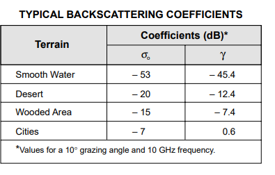
SCR=(sigma_target*4*altitude)/(10^(sigma0_surface/10)*pi*(altitude^2+distance^2)*deg2rad(beamwidth))
And that’s not equivalent of 4.14 with 4.12 substitution. Its equivalent of 4.14 multiplied by [sqrt(altitude^2+distance^2) * deg2rad(beamwidth)]. Such equation gives SCR for clutter at range Rc = sqrt(altitude^2+distance^2) and target at much closer range which equals to Rc / quadroot(Rc * deg2rad(beamwidth)). Of course, that’s much better SCR than eq.4.14 gives. All this looks weird to me. Thoughts?
Also note that missile have much wider beamwidth than fighter. 15deg vs ~3deg, five times wider. This results in SCR 25 times worser (because footprint area 25 times bigger) at the same circumstances.
Guys, in my opinion there are no major issues with notching itself. Of course, there may be some tweaks on normalized rcs of surface or we make different values for different surface types, but this will not change situation drastically.
BUT
In this particular case (see first post of topic) the problem is that INS data does not updated by seeker measurements, so without datalink updates missile performance after losing track of maneuvering target is degraded. We know about that and missile development in part of merging seeker data, datalink and INS data is not finished. Such systems may be built in several ways and I have some thoughts on that, but it is not as simple as it may looks like and good solution requires additional research.
There is no any contradiction if we suppose that range at wich missile stops to incorparate data links is less then Pitbull range.
The paper is a very useful, thanks.
Thank you! These patents are really interesting, but I’m afraid that’s not a solution. Not a full at least. See explanations below.
Admit right now we have 100% probability of detection (and lock) for 2dB SCR, and 1.5dB for detecting at all (extremely low values!). Of course, if I’ll try to implement this thing missile tracking capabilities will grow up to 15 or maybe 30% at 1dB SNR. But practically you wont notice any difference because in most of cases SNR is much lower that 1dB. It could easily be -10dB or worse! So, even this new method will provide very low detecting probability in such circumstances.
Additionally, there will be troubles for radar if beaming target will use chaff
That’s not quite true. First of all, angle difference limited by beamwidth. If you track a target seeker LOS is pointed at the target and difference limited by half of beamwidth. Practically it will be even less than half because you need to put some ground surface inside of beam to have significant return. In case of ambiguous clutter return when patches of clutter superimposed in range bins angle difference may be small(signal from several patches located at different angels for radar will look like signal from one bigger patch located at some average angle). Also, it’s hard to say what average angle of clutter will be in most DCS situations.
As I said the missile has such extrapolations, but there is a problem with updating data for extrapolation. It will be solved.
I did not say exactly that. There is no any problem with resolving range ambiguity for ordinary target. I was talking about extended target (about ground clutter in particular). Please see explanations above.
Be assured modern PD radars still have problems with beaming targets tracking and try to contend with this generally by inertial tracking(extrapolation) or LPRF using. If it’s the ESA radar there are several additional methods to contend with this issue.
BTW. Proposed method does not look as good improvement for fighter radars because they usually have narrow beam 3 deg circa. (so only 1.5 deg halfwidth…)
Yep, but we have lots of different high-priority tasks, so can’t promise such features soon. Will add to wishlist.
The issue here is that in MPRF when you feed the returns into the associated apparent range bins then feed that into the attached doppler bins a good portion of that clutter will fall into another doppler bin whereas the target will be in one range bin. This will reduce the amount of energy that the target return has to compete against to whatever happens to fall into the same doppler bin. The MLC is not all at the same doppler as the target and the larger the look angle and the larger the velocity of the missile the more that energy is distributed. Were in STT not search as well, currently it seems that the notch is 100kts'ish hopefully you can give the exact number. But In STT your tracking gates are going to be much much smaller then this. Typical values I see referenced are 15m/s in total width. And the missile should really only loose the tracking gate if the target is not competing with clutter. But that would mean that you could get a lot closer to the central MLC return (especially at close range and for high RCS say being side on or given your belly to the target) without loosing track. If not right on it if the noise is low such as in only very low look angles or low return clutter like calm seas.
Spoiler
Also we can't ignore factors like integration time and PDI for S/N.
-
Yeah seems this is part of the notch behavior discussed before:
my thoughts on the matter are layed out in this thread.
-
2
-
-
On 6/6/2022 at 4:39 AM, Маэстро said:
Hi GGTharos, good if pilots have data from instrumented shots, but even if they be able to talk about we would need data for set of shots to understand how the avarage missile looks like.(There is always some uncertainity due to different air and motor charge temperature, some devation on total impulse, hence there may be deviation on that Mach 0.2 or so)
Regarding AIM-7 guidance - it's not related thing(and it works correct). If we talking about top speed/ballisitcs we should assume that missile fly stright ahead without any maneuvers. Manuvering is a separate case.
BTW I'have found that nozzle exit area was not defined for AIM-7 family in OB. It was fixed internally, but not released. We will include it into the next patch. That will give missile additional 0.1 Mach of top speed

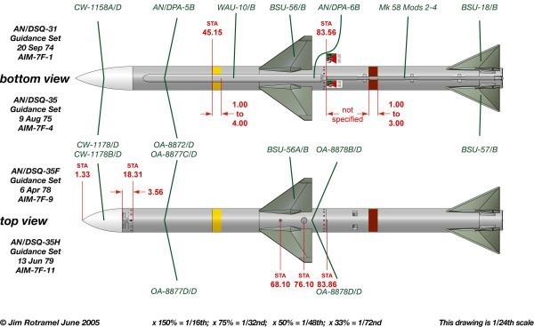
Another interesting thing is AIM-7 radome. It's different for an old and newer versions, see attached. Right now we have drag of old radome with a higher Length/Diameter ratio for all aim-7 versions. I plan to run CFD someday to find out the difference in zero-lift drag value. Think it may be 5-10% higher for M/H/P versions of missile.
I'd seen some documents reference two different nose cons for the 7F one that is better for the sensor and one better for aero performance i'd just never seen the difference. Do we know which one was in more common use?
edit:
Didn't the 7M get another redesigned nose again from the 7F? From just one quick image grab it seems that it's closer in shape to the older but more aerodynamic nose cone:
-
There will be at some point it will be able to go active on its own. Currently the only benefit is better chaff resistance.
-
22 minutes ago, Beamscanner said:
As for everything else, its pure speculation. Sure, we can assume that the missile to programmed to 'coast' the track in memory. But it cant know a split S from a normal 90 degree notch.
The AIM-120 has an INS so by default its going to know the targets location in 3D space. You could easily look for a split S based off of this information. We know from documentation that there is a method by which there are adjustments made to compensate for the split-S on the AIM-7. I highly doubt the amraam would not have something similar if not even better.
-
2 hours ago, Маэстро said:
Ok, then please, tell how you will resolve ambuguties and seprate target from clutter signal if all range bins filled with clutter?
A long time ago
According to razbam's galinette DCS was only returning a constant value for the RCS even when side on. I linked him to your post and I think he said he was going to talk to you. Are you sure this is implemented?
-
1
-
-
19 minutes ago, KlarSnow said:
No they wont because they are range bins... why would they have any of the main lobe ground return in them. IF they are sorted by range and in the situation presented at the start of this thread. There is no Main Lobe or side lobe clutter in the 2.5 Nautical mile range bin. So if you sort it by range and receive the unambiguous range benefits of MPRF with PRF Jitter, how is the Main lobe or side lobe doppler that is 20 miles away getting into the 2.5 nautical mile range bin. And if it is, how is it of such magnitude that it is overwhelming the target return.
None of this is happening on a single pulse.... This is all integrated over several pulses on several PRF's
Yeah i'm still a little fuzzy on this but don't rage bins come before the Doppler filters?
-
1 hour ago, Маэстро said:
Ok, then please, tell how you will resolve ambuguties and seprate target from clutter signal if all range bins filled with clutter?
A long time ago
Part of what's going on here too, aside from mprf stuff as i'm not quite up far enough in my reading to know the exact answer I know it can be done though. We can't ignore S/N either, i've seen missiles notched at less then two miles. Except that there's a ton of things that should make the target compete even against a large MLC. The STT nature of the track ensures that integration time is extremely high effectively infinite, monopulse itself also has S/N benefits, side on RCS will be huge as well, the employment of PDI will also help. The type of terrain would also be important:
https://patents.google.com/patent/US4559537
method of tracking targets in MLC patented by Raytheon in 1985 right when AIM-120 development was in full swing.
Also from earlier are you using 15deg for the beamwidth for the amraam? That's huge way beyond a reasonable value. MACE uses a value of ~3-4deg
Edit:
The video posted by Vatikus is exactly how you deal with mprf ambiguities i'm still working on understanding the exact mechanisms behind mprf but as shown in the vid it can be done easily. There's a reason MPRF is so widly used.
-
3
-
-
3 minutes ago, KlarSnow said:
Why not, this paper seems to think you can do exactly what you are saying it cannot.
As does just about any other you go and look at, where is your source that extended clutter prevents MPRF from resolving targets. Because every source I, and everyone here but apparently you has seen, says exactly the opposite. Every source on MPRF says MPRF has range and velocity ambiguity, but with techniques like PRF jitter and various processing techniques it is the most reliable method of tracking targets at all aspects in lookdown.
MPRF is specifically chosen to help with sidelobe and main lobe clutter because it reduces the amplitude in the range cells
https://calhoun.nps.edu/handle/10945/5544
What exactly is the reason this does not work?
PRF jitter has issues it reduces range what radars use now if PRF switching. You switch between a few distinct PRF's usually 3-4 and get the same effect without as many issues.
-
4
-
-
16 minutes ago, Маэстро said:
Oh..you really think I do not know about abmiguty resloving? The thing is.. you can perform such resolving for separate relatively small target. That would not work when you have such extended "target" as clutter.
You absolutly can in MPRF especially in a monopulse seeker with its extremely good range resolution, especially in mprf. And considering the amraam's lack of need for long range I don't doubt its pulse width isn't quite small fractions of a microsecond. Not to mention other techniques developed to break out closely spaced contacts. Which monopulse seekers are capable of determing and even partially solving for multiple contacts inside its resolution cell.
-
5
-
-
30 minutes ago, Маэстро said:
10KHz is not HPRF. Its a lower bound of MPRF. RCS increasing at perpendicular angles of sight is also implemented and gives up 40 times increasing in RCS. Before saying somthing about visibility of tagets above clutter it's better to calculate it. Otherwise it's just assumptions.
I know that. pitch-AOA means pitch minus AoA, that gives direction of velocity vector.
So RCS increasing when side on is implemented now?
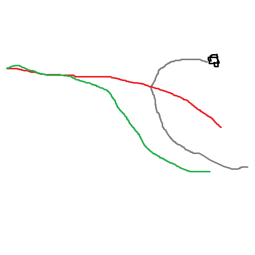
Also I know that there are references even the AIM-7 docs to "anti-Split S logic". Exactly what this entails is not discused but its not hard to make a reasonable guess. Its almost certaintly just a damper put on the acceleration command if the targets angular position and velocity meet a certain set of criteria. As such the flight path would look like the red line below instead of green which is what it does now:
1 hour ago, KlarSnow said:So you are saying you are range gating with HPRF yeah of course that isn't going to work at all if your Range ambiguity is as large as your seekers detection range. What exactly is the point of that feature then.
You can solve for range ambiguity even in HPRF just use PRF switching.
1 hour ago, KlarSnow said:Also HPRF seekers start to have good range ambiguity at very close ranges, once you get close enough that you are receiving returns before the next pulse goes out. it should be quite possible to have good range ambiguity at 2-3 miles with an HPRF X band seeker.
Sorta, HPRF seekers are highly ambigous in range so i'm not sure if the ku/ka band amraam seeker would even have an unamiguous range of even that far.
1 hour ago, KlarSnow said:Range gating with HPRF is completely pointless so if this was known why did you implement it like this.
Its hard to range gate with HPRF as due to the range ambiguities its hard to seperate clutter from the target when putting returns into the range bins.
1 hour ago, KlarSnow said:And why is this not using MPRF which does not have any of this issue.
Exactly
1 hour ago, KlarSnow said:The target return from that RCS that is at 2-3 miles that just flashed a reflective billboard at the missile isn't enough to keep it visible above main lobe clutter which while large is also 22 miles away down the direct line of sight. You are also assuming that the radar once in track isn't angle gating the target and ignoring all returns that aren't within a very narrow window around the target.... precisely to mitigate this kind of issue and increase SnR.
Finally this entire lookdown happens over water. Unless you are modelling a severe sea state, water has nowhere near the direct clutter return that land does, most of the energy in this scenario is reflected off the surface long of the target, yes some will still be coming back, but not nearly as much.
So yeah for what you've implemented working as intended I guess, but I question why range gating was implemented on a radar (or mode of the radar) that it is apparently useless on, and there are so very many other things that a computerized missile of this sort can do to combat this. The notch is a known feature of working with Pulse doppler radars and has been for over 60 years, that a very modern missile as you have implemented it has zero effective countermeasures against it seems rather wrong.
Now if you were to make this in MPRF, that's a completely different discussion, and is what everyone was assuming.
Ontop of all of this Monopulse systems are renound for massive S/N gains over even planar arrays. Which would help even more. And yes range to ground clutter and type should be factored in I don't know if it is currently.

-
2
-


Ракеты в DCS
in DCS World
Posted · Edited by nighthawk2174
This is a well-known limitation of lattice fins; it doesn't matter what you believe lattice fins are a not some big unkown. The data comes from a publicly available report. There's a reason no one is using lattice fins on their latest missiles anymore not the Europeans, Americans, Chinese, Japanese, Koreans, etc. The improvements you could possibly get, you can achieve more effectively without the downsides by using thrust vectoring.
ANALYSIS OF GRID FINS AS EFFICIENT CONTROL SURFACE IN COMPARISON TO CONVENTIONAL PLANAR FINS