

Heling
-
Posts
79 -
Joined
-
Last visited
Content Type
Profiles
Forums
Events
Everything posted by Heling
-
I do not know. I switched from a Mega 2560 to a Uno and now it works. What a hassle. I deal with the forum here and then something. Thank you guys!
-
At the moment, I have DCS-A10 started like a PC-game on my monitor. The DCS BIOS Hub is running and he shows me the changes on CMSC. And then I connect to my Arduino port. In this moment, my default text disappears and nothing fills the given positions the OLED. I think the viewport should be okay in this configuration. The UHF-Frequency works fine, but with a light different function. But I can't do that with the CMSC: void updateComDisplay(int changed,char* newValue) { comDisplay[changed] = cleanUpCom(newValue); display.clearDisplay(); display.setCursor(0,10); display.print(comDisplay[0]); //display.setCursor(0,10); //display.print(comDisplay[1]); display.display(); } char* cleanUpCom(char* newValue) { switch (newValue[0]) { case '`': newValue[0]='1'; break; case '~': newValue[0]='2'; break; } return newValue; } void onUhfFrequencyChange(char* newValue) { updateComDisplay(0, newValue); } DcsBios::StringBuffer<7> uhfFrequencyBuffer(0x1180, onUhfFrequencyChange);
-
Yes, inside the DCS-BIOS function nothing works. In my example below you see I tried with a given string "Test" but it will not going to the OLED. void onCmscTxtJmrChange(char* newValue) { //newValue = ("Test"); // not working :( lcd.clear(); // not working :( lcd.sendString(newValue,0,0); // not working :( } DcsBios::StringBuffer<8> cmscTxtJmrBuffer(0x1096, onCmscTxtJmrChange);
-
What I wrote inside the 'void setup' appears on the OLED without problems. The I2C works fine.
-
It' very similar to my codes and still no output with your code. Will try with a LCD and LiquidCristal -Library. I will report here.
-
Hi folks, I've a short code for testing. Whatever I tried - there is no output possible inside the function. I worked with different libraries, but it's still no working. Watch the comments inside the code. What's the trick with DCS-Bios? /* CMSP-Display */ #define DCSBIOS_IRQ_SERIAL #include <DcsBios.h> #include <Wire.h> #include "OLedI2C.h" OLedI2C lcd; // The output to the 20 x 2 OLED works fine her in the setup area: void setup() { DcsBios::setup(); Wire.begin(); //lcd.setContrast(0x0A); // contrast as 0x00 to 0xFF lcd.init(); lcd.sendString("SBY AIR ",0,0); // This three lines aro working good! lcd.sendString("c120f240",12,0); lcd.sendString("ACTIVE ",0,1); delay(999); } // Here the function without any output: //Jammer Display -------------------------- void onCmscTxtJmrChange(char* newValue) { //newValue = ("Test"); // not working :( lcd.clear(); // not working :( lcd.sendString(newValue,0,0); // not working :( } DcsBios::StringBuffer<8> cmscTxtJmrBuffer(0x1096, onCmscTxtJmrChange); void loop() { DcsBios::loop(); }
-
It's a known effect if the background is very softened
-
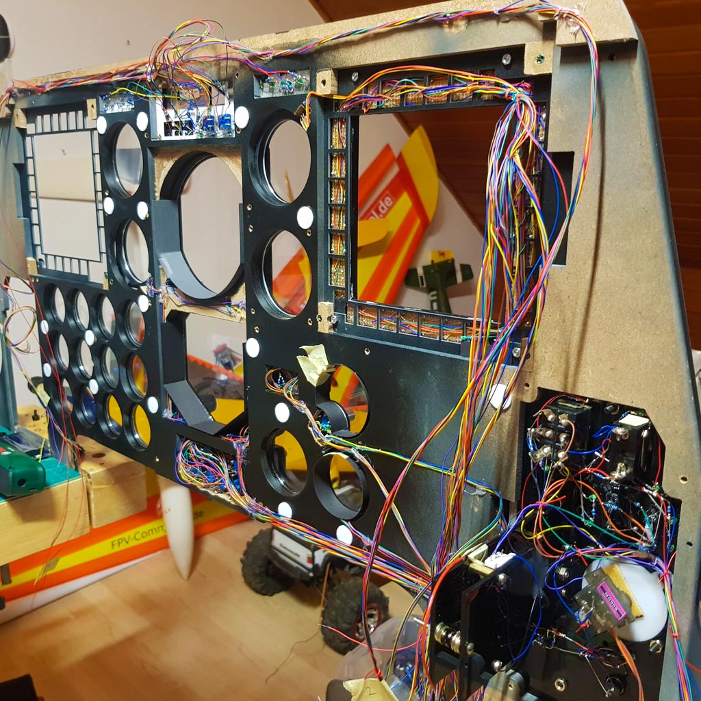
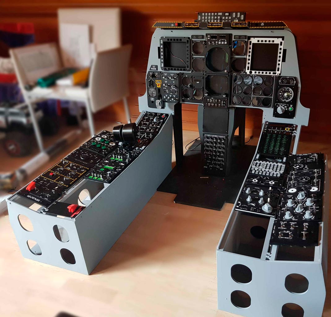
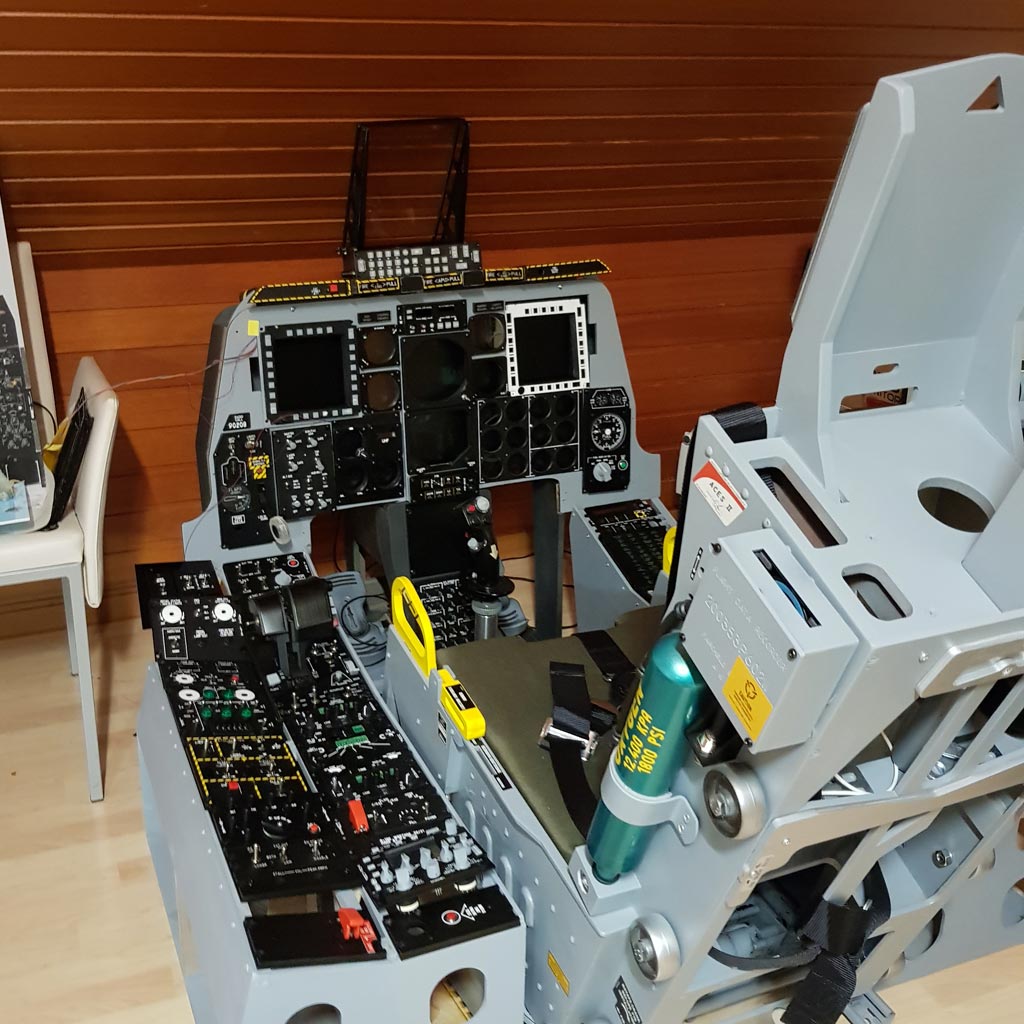
Hello romeo kilo, 18 months ago I found your thread here and was immediately hooked on your project. After a few sleepless nights, I downloaded your wonderful files. Without this I would never have started. Now there is a copy of your cockpit here with me. Not ready. I started wiring this winter and want to have the main panel fully functional in a few days. Wiring and programming is sure to be the biggest work. Previous knowledge is essential here. Luckily I'm an electrician and retired;) Romeokilo, thank you very much for your extensive preparatory work! Here are a few photos. Michael

-
I'm here with a similar problem. The Code looks clean, but inside the function is like a closed castle. Nothing will work inside. I tried four libraries with the same result. This happens in further codes Need help! /* CMSP-Display */ #define DCSBIOS_IRQ_SERIAL #include <Wire.h> #include "OLedI2C.h" #include <DcsBios.h> OLedI2C lcd; // The output to the 20 x 2 OLED works fine her in the setup area: void setup() { DcsBios::setup(); Wire.begin(); //lcd.setContrast(0x0A); // contrast as 0x00 to 0xFF lcd.init(); lcd.sendString("sby air ",0,0); lcd.sendString("c---f---",12,0); lcd.sendString("active",0,1); delay(999); } // Here the function without any output: //Jammer Display -------------------------- char onCmscTxtJmrChange(char* newValue) { lcd.clear(); lcd.sendString(newValue,0,0); } DcsBios::StringBuffer<8> cmscTxtJmrBuffer(0x1096, onCmscTxtJmrChange); void loop() { DcsBios::loop(); }
-
Warum nur habe ich diese Antworten erwartet? In einem Forum übers militärische Fliegen ist es nur logisch. Hier tummeln sich auch reale Piloten aus den unterschiedlichsten Nationen und diskutieren hier mit jedem. Da kann schon mal ein Wort zu viel gesagt werden über Technik oder Verfahren. Der KGB, oder besser FSB und SWR wären schön blöde das nicht zu tun. Ich denke an "Mover", dem ehem. amerikanischen Piloten, der in seinen Videos explizit bestimmte Verfahren nie zeigt. Bei uns fällt viel zu leichtfertig der Satz: Ach die wissen doch eh schon alles! Weißt du es?
-
Hallo Leute, bin gerade auf diesen Thread gestoßen und etwas irritiert. Bundeswehrthemen in einem russischen Forum. Manche Texte enthalten sogar Spuren von Insiderkenntnissen... Bei aller Liebe zum Sim-Hobby - bitte versucht nicht mit Kenntnissen zu glänzen die innerhalb eurer Staffeln zu bleiben haben. Wir Deutsche sind an vielen Stellen etwas zu offenherzig. Was glaubt ihr wer hier stündlich nachschaut, was es neues in der BW gibt? Euer Heling
-
Hallo Rocco, war es nocht so, dass westliche Werte ein W und östliche eine O davor hatten? Bei rein mathematischen Systemen ein Minuszeichen anstelle von "O"?
-
Just a short question: The 487 bus needs on both ends terminal resistors to keep the line. More than two are bad, no one is also bad. Do you have an oszilloscope for watching the signals on the 487 bus? If you use the MAX487 modules - they've all resistors, but only one is allowed. May be there is your problem? Another thing is, the Arduino mega carring the master must not have any other inputs or outputs than the Max487. See https://en.wikipedia.org/wiki/RS-485
-
Shure! Read the first sides...
-
Danke! Besser geht es nicht!:thumbup:
-
@Blech, Danke! Genau so etwas habe ich gesucht:thumbup:
-
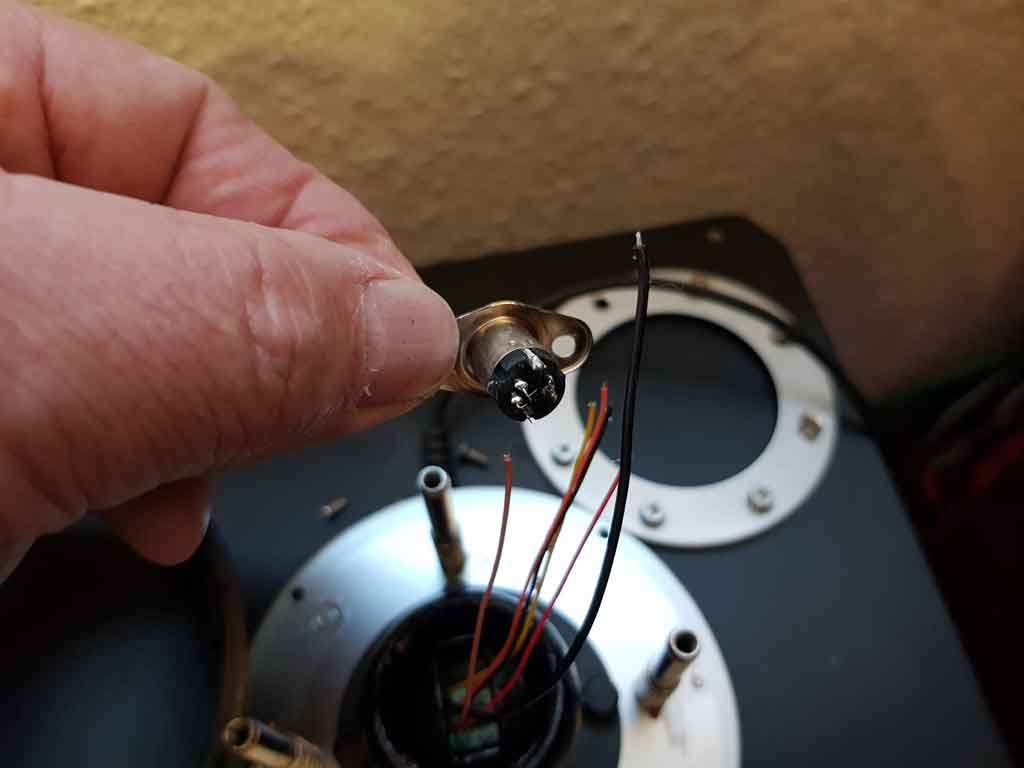
Mein Joystick brach beim Ansturz von Tisch und riss dabei die Kabel komplett vom Stecker. Wer kann mir sagen, welche Farbe an welchen Pin gelötet werden muss? Die zerbrochene Glocke, das einzig zerbrechbare Teil des Joysticks, ist nicht als Ersatzteil von Trustmaster erhältlich. Alles andere ja. Ich habe sie mit 2-K-Kleber repariert und zusätzlich vier 3mm Gewindestangen in vorbereitete Bohrungen entlang der Bruchstelle verstärkt. Das sollte auch halten, wenn eine Verlängerung noch größere Kräfte auf die (Soll-)Bruchstelle ausübt.
-
Hallo Ian, boah, da bin ich froh. Ich zweifelte schon an meinem Verstand. Ich löte seit 50 Jahren und dann das hier ;) Also lege ich das Projekt CLP erst mal auf Eis und mache die hundert anderen Sachen. Danke Dir! PS: Habe mit der vorherigen Bios-Version eine funktionierende CLP...!
-
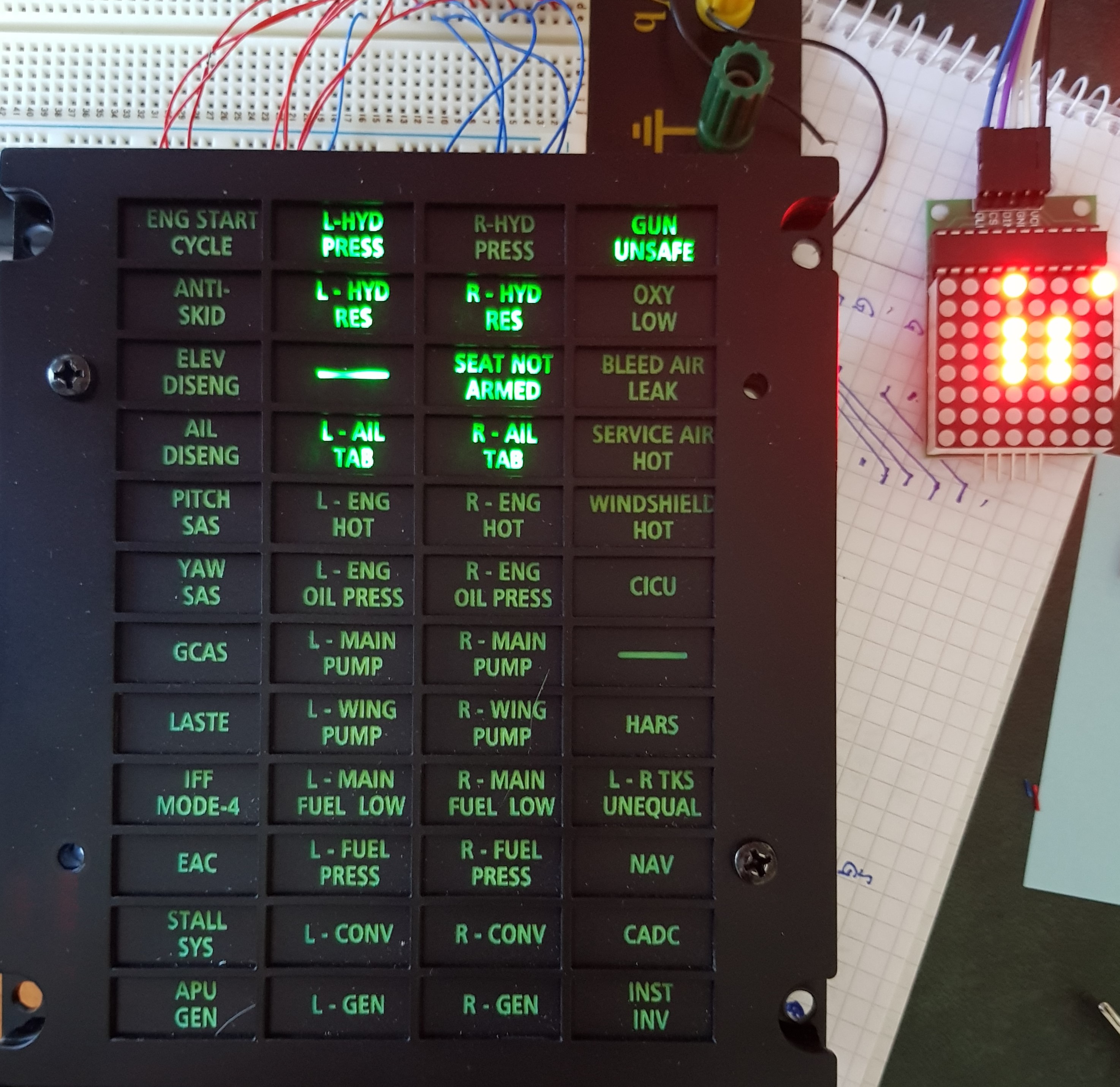
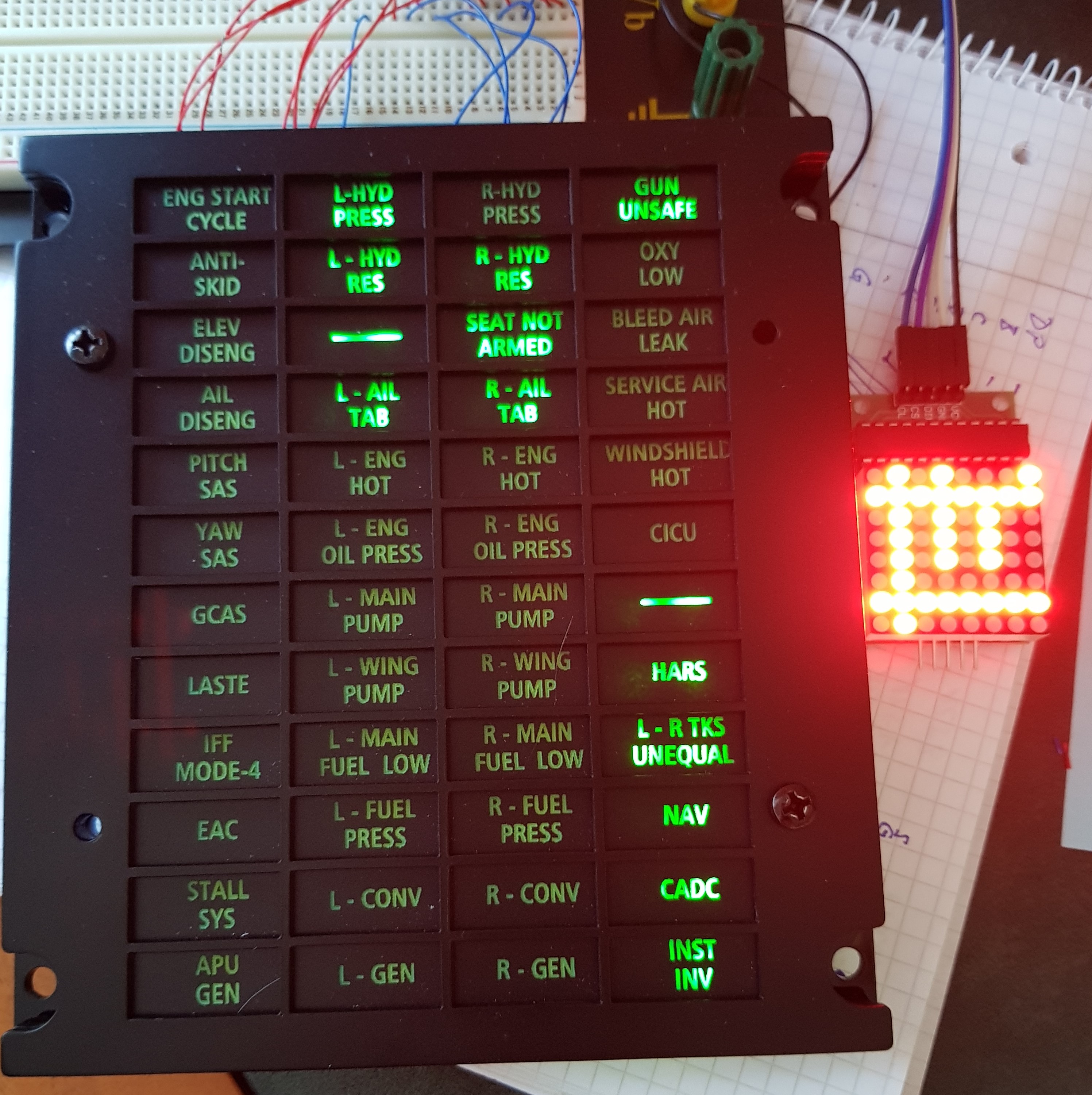
Danke für die Tipps. Habe jetzt eine 8x8 LED-Matrix parallel geschaltet. Diese zeigt, das Segment A + F nicht benutzt sind. Auf dem Board habe ich sie auch nicht verdrahtet. Aber auch auf der LED-Matrix leuchten schon einige LEDs auf, sobald die serial connection bei kalter A-10 gestartet wird :( und beim Lampentest gehen auch nicht alle an. Erstaunlicherweise kommt es darauf an ob ich zuvor mit 'memset(max7219_rows, 0xff, ...);' alle LEDs AUS oder AN hatte. Es leuchten dann mehr und weniger auf (s. Bilder: links zuvor 0x00, rechts zuvor 0xff) Ich habe den Sketch tausendmal gecheckt und kann keinen Fehler finden. Woher kommen die Daten, die die LEDs ungewollt einschalten? Ich bin echt für jeden Hinweis sehr dankbar, da mich das Problem schon tagelang aufhält.
-
Nicht alle auf einmal ;) Es liegt wohl am BIOS. Ich habe verschiedene Varianten aus den entsprechenden Threads getestet und alle liefern exakt den gleichen Durcheinander. Ich habe es auf Mega, Nano und Uno getestet. Immer das gleiche Bild, auch direkt am MAX7219 Ausgang. Kann das jemand nachvollziehen?
-
Caution board Problem Hi Habe ein Caution board und die Ansteuerung von Craig S. übernommen. ( ) Physikalisch alles okay. Aber sobald das DCS-Bios die Werte liefert stimmen die Positionen nicht. Auch schalten sich schon ein paar LEDs ein wenn die A-10 noch ohne Batterie ist. Ich raffe das mit der Matrix nicht. Der Code ist exakt wie Craig's und doch klappt es bei mir nicht. Er hat seitdem auch nichts am Code verändert. Hat jemand eines gebaut und es läuft untere DCS-BIOS? So sieht mein Code aus: /* Tell DCS-BIOS to use a serial connection and use interrupt-driven communication. The main program will be interrupted to prioritize processing incoming data. This should work on any Arduino that has an ATMega328 controller (Uno, Pro Mini, many others). */ #define DCSBIOS_IRQ_SERIAL //#define DCSBIOS_DEFAULT_SERIAL #include <LedControl.h> #include <DcsBios.h> //pin12 is connected to the DataIn //pin10 ito the CLK //pin11 to the CS LedControl lc=LedControl(12,10,11,1);//DIN, CLK, CS, # of IC's unsigned char cl_row_map[48] = { 0,2,4,6, 0,2,4,6, 0,2,4,6, 0,2,4,6, 0,2,4,6, 0,2,4,6, 1,3,5,7, 1,3,5,7, 1,3,5,7, 1,3,5,7, 1,3,5,7, 1,3,5,7, }; #define SEG_DP (1<<7) #define SEG_A (1<<6) #define SEG_B (1<<5) #define SEG_C (1<<4) #define SEG_D (1<<3) #define SEG_E (1<<2) #define SEG_F (1<<1) #define SEG_G (1<<0) unsigned char cl_mask_map[48]= { SEG_DP,SEG_DP,SEG_DP,SEG_DP, SEG_B,SEG_B,SEG_B,SEG_B, SEG_C,SEG_C,SEG_C,SEG_C, SEG_D,SEG_D,SEG_D,SEG_D, SEG_E,SEG_E,SEG_E,SEG_E, SEG_G,SEG_G,SEG_G,SEG_G, SEG_G,SEG_G,SEG_G,SEG_G, SEG_E,SEG_E,SEG_E,SEG_E, SEG_D,SEG_D,SEG_D,SEG_D, SEG_C,SEG_C,SEG_C,SEG_C, SEG_B,SEG_B,SEG_B,SEG_B, SEG_DP,SEG_DP,SEG_DP,SEG_DP, }; unsigned char max7219_rows[8]; void setup() { DcsBios::setup(); memset(max7219_rows, 0xff, sizeof(max7219_rows)); lc.shutdown(0,false); //turn on the display lc.setIntensity(0,15);//set the brightness lc.clearDisplay(0); //clear rthe display and get ready for new data } void updateCautionLights(unsigned int address, unsigned int data) { unsigned char clp_row = (address - 0x10d4) * 2; unsigned char start_index = clp_row * 4; unsigned char column = 0; unsigned char i; bool is_on; for (i=0; i<16; i++) { is_on = data & 0x01; // set caution light state (clp_row, column, is_on) if (is_on) { max7219_rows[cl_row_map[start_index+i]] |= cl_mask_map[start_index+i]; } else { max7219_rows[cl_row_map[start_index+i]] &= ~(cl_mask_map[start_index+i]); } data >>= 1; column++; if (column == 4) { clp_row++; column = 0; } } } void onClpData1Change(unsigned int newValue) { updateCautionLights(0x10d4, newValue); } DcsBios::IntegerBuffer clpData1(0x10d4, 0xffff, 0, onClpData1Change); void onClpData2Change(unsigned int newValue) { updateCautionLights(0x10d6, newValue); } DcsBios::IntegerBuffer clpData2(0x10d6, 0xffff, 0, onClpData2Change); void onClpData3Change(unsigned int newValue) { updateCautionLights(0x10d8, newValue); } DcsBios::IntegerBuffer clpData3(0x10d8, 0xffff, 0, onClpData3Change); void loop() { DcsBios::loop(); // update MAX7219 unsigned char i; for (i=0; i<8; i++) { lc.setRow(0, i, max7219_rows); } } Und so die Matrix (von hinten - ENG START CYCLE ist oben rechts):
-
Hi Arjan, do not engrave so deep in the acrylic. It's more original if you just come through the paint layers and then so much that the acrylic is roughened. Try it out. I use 250mm/sec and 5-6 Watt for the best look.
-
Moin, super! Danke für die Infos. Ich werde mal die erste Möglichkeit untersuchen. Ich möchte möglichst wenig Hardware zwischen Schalter und DSC haben. Das vereinfacht Aufbau, Fehlersuche und Wartung.
-
Hmm, Ich habe mit dem Thema Verkabelung zu DCS gerade erst begonnen. Da gibt es offensichtlich noch große Wissenslücken bei mir...:huh: Wenn es da einen einfacheren Weg gibt, nehme ich den gerne. Wo finde ich was zu deiner Lösung? Immerhin könnte ich 100 Schalter mit einem Arduino abfrühstücken!
-
Noch eine Grafik zum Verständnis. Das sieht erst mal merkwürdig aus, aber an jeder Kreuzung sitzt ein Schalter oder Taster. Wenn ich "A" drücke, wird Pin 2 und 13 high, usw.


.jpg.51e0d0f19a1d282f8bf84ca1b01a0182.jpg)