Alex_rcpilot
-
Posts
547 -
Joined
-
Last visited
Content Type
Profiles
Forums
Events
Everything posted by Alex_rcpilot
-

My engineering approach to a Hornet pit build project
Alex_rcpilot replied to Alex_rcpilot's topic in Home Cockpits
Alright guys, time for show n' tell. My original plan is pretty much complete now. Voilà! (Image attachment fixed now) I've been working on and off this project for the past few months. Sometimes it felt like a rollercoaster ride coz they did screw up quite a few things at the factories and I had to halt the whole project and join them working out a solution. Fortunately it paid off pretty well. Pit building is an addiction for which there's no way out. As this project moved forward, the original plan has evolved too. I've enjoyed myself and I'll keep logging back to share my enthusiasm and new progress from time to time. Hi Lobinjaevel, generally thicker material helps distributing light more evenly. And it's more important to strategically plant those LEDs. If you 3D print your prototype panels, make sure you properly sand and polish the surface before applying the paint. It's very difficult to get it right the first round. I've got a hug box full of failed panels, that's how I learned it in a few years. Thanks man. Kind of. They are regular shift registers with digital outputs. I didn't need brightness adjustment capabilities, so no ASICs were required. Hi Razi. I'm not a full-time software developer, but I do write my own C# or C++ applications. C# comes in handy for proof of concepts. For coding the release version I'd always turn to professional programmers. The following doesn't necessarily work for you, but since you've asked, I always start with a notebook and a pen to lay down my initial ideas, then a group of blank documents and spreadsheets are created and updated alongside the actual software project to keep track of latest architecture, key flow charts, algorithms, data structures and custom protocol stacks. A complete set of documentation makes it a lot easier for both the professional programmer and myself optimize the software in the future. The custom protocol in particular helps me keep track of the firmware project in parallel with the software side. TBH I haven't read much about software, so I can't make any suggestions even if I knew your goal. But I'd be glad if my experiences could help you in some other way. Hi John, it took so much longer than I thought, lol. But it's moving forward anyway. I'll be back soon with more updates.
-
My engineering approach to a Hornet pit build project
Alex_rcpilot replied to Alex_rcpilot's topic in Home Cockpits
Sorry guys, I've been travelling a lot lately, work has kept me busy. There has neverthelsss been significant progress with this project. I'll be able to log back with more replies and updates in a week or so. -
My engineering approach to a Hornet pit build project
Alex_rcpilot replied to Alex_rcpilot's topic in Home Cockpits
Coding got interrupted by the arrival of the indexer core block. It's just the core structure for now, sheet metal cover and lever comes later. I took some time to solder the PCB. Light looks acceptable, gotta edit the drawings a little bit for those symbols in the front next time.
-
My engineering approach to a Hornet pit build project
Alex_rcpilot replied to Alex_rcpilot's topic in Home Cockpits
Thank you, hope you liked it. Hi, it's a regular 8" TFT with an HDMI interface. 800x480 resolution. I've taken measurements of the viewport output on this display before throwing those window openings on my face plate design. -
My engineering approach to a Hornet pit build project
Alex_rcpilot replied to Alex_rcpilot's topic in Home Cockpits
Will post more updates soon :thumbup: Thanks man, it came in pretty handy. I thought about replacing the system legacy property sheet, but it came so low on my priority list that it eventually dropped out, lol Hold my beer, when I'm done building my man cave, IMA join the same caveman club. Yup, it's ordinary clear acrylic painted over. However, it was a painstaking job to strategically position the LEDs. You'll get used to it :smilewink: Might feel kinda intimidating at first, but it ain't rocket science and options are abundant. I've merely picked one possible solution. Looking forward to seeing more from you guys. -
My engineering approach to a Hornet pit build project
Alex_rcpilot replied to Alex_rcpilot's topic in Home Cockpits
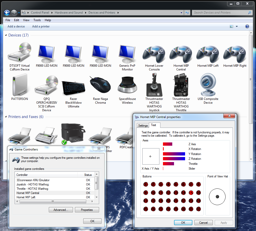
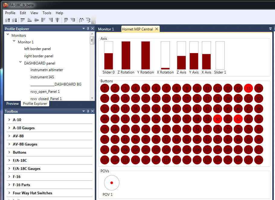
Thank you Blue, I guess it's the best option for me, based on the kind of resources I have. Hi Fused, UFC is coming along pretty well. The TFT display has an 800x480 resolution, but its HDMI driver board offers alternative settigns like 1920x1080 / 1600x900. I'm using 1280x720 since it's exactly a quarter the size of my main monitors, and I could squeeze in another one without triggering any compulsive disorder. Besides, 1280x720 is the lowest resolution there is without making up a custom profile in the advanced graphic settings, I guess it means less impact on FPS. It's a nice weekend for coding, I'll get to the MFD bezels some other time. I've split the main instrument panel into 4 sections each running on a separate USB card. The cards are all physically identical so it minimizes my coding efforts. They are programmed so I can configure them individually to show up as different devices as in the following screenshot: I didn't use Arduino because of its physical limitations. Space budget is tight and all the electronics have to be customized, the AVR chips are probably too weak for the kind of workload I'm throwing at them. Plus, I need more than 32 buttons per device, and I need all the pots and switches as DirectInput axes and buttons which are much more responsive on Windows. Windows property sheet only shows a maximum of 32 buttons, for access to the rest of them I just use Helios, simply find the controller from the list of interfaces. I like to organise them in rows of 16 buttons when I debug, it's much quicker to navigate. The ones that are lit up in the screenshot are some ON-OFF-ON type toggle switches or buttons. I've programmed them to also send out a button press when they reture to OFF position. Those are the OFF positions being triggered. Catch you guys later :)
-
My engineering approach to a Hornet pit build project
Alex_rcpilot replied to Alex_rcpilot's topic in Home Cockpits
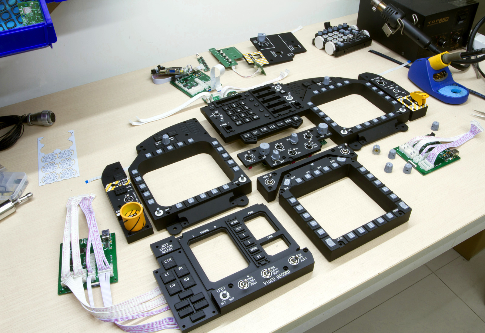
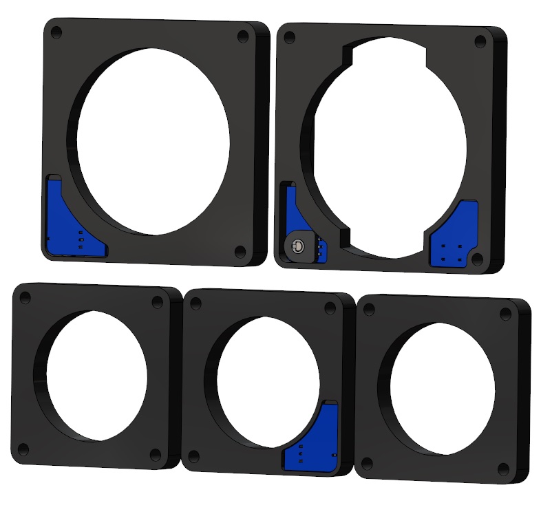
Yeah man. BTW, images with Hornet pit dimensions are a bit hard to come by, and that one you shared is one of the rare drawings I also found. I did cross-reference my design with it, and it helped pin down some of the most critical dimensions. Here's what I should end up with if nothing goes wrong: Looking forward to getting the electric actuator fitted in the back too. Hi and thanks Gotwake, I hope more stuff will come back soon. Hi Fusedspine, TBH I'm not sure about that. Kinda want to see everything fit together so I have a pit to experiment with, must be a guinea pig thing:D Then if it does become popular at least I'd know everything is reliable. lol, yeah that cheeky little sucker was about to get some wires replaced before the F-18 parts came back. I ran out of black wire when I was assembling it. Now I've just completed this task. Hated these makeshift blue wires, screwed up my color coding system :) Hey thanks Blue, you've also done lots of amazing work there. To answer your question, and also respond to sk000tch and mrwell's comments here: Yes and no, I did use 3D printing before resin casting those buttons. But most of the parts are CNC milled out of solid blocks of acrylic. They were then painted before laser engraving. The main reason is that there's no way I was able to produce the kind of flat surface and the smooth finish I wanted with 3D printing. The following images should illustrate what results I was expect of these parts. DDI Buttons with the circular recess: Video recording panel: I'll shift my focus to firmware debug in the next few days. Hopefully will have more to share soon.
-
My engineering approach to a Hornet pit build project
Alex_rcpilot replied to Alex_rcpilot's topic in Home Cockpits
Alright guys, I've been gone for a while, yet by no means have I let this project slide. Consider the following pic an appetizer for what's coming next.
-
My engineering approach to a Hornet pit build project
Alex_rcpilot replied to Alex_rcpilot's topic in Home Cockpits
Hi Guppy, thanks for the advice. I've checked the line of sight in the model and there's indeed some obstruction by the HUD base between the head and the monitor. The mannequin used in the model measures only 5'8″ tall. good thing is both the monitor and the seat are adjustable. I didn't bother modeling the actual monitor I'm using, so I've made a duplicate of the same 28" monitor as the one sandwiched inside the front console. The front console is designed to fit universally with commonplace computer desks and it's the first piece to be deployed in the setup. The monitor or potentially other forms of visual system should then be adjusted accordingly. Finally, when my friends drop by and try this setup, there's an electric cylinder integrated inside the seat for them to adjust with the flip of a toggle switch. I think it should solve the problem. -
Advice on using LED's for warning light panel
Alex_rcpilot replied to lesthegrngo's topic in Home Cockpits
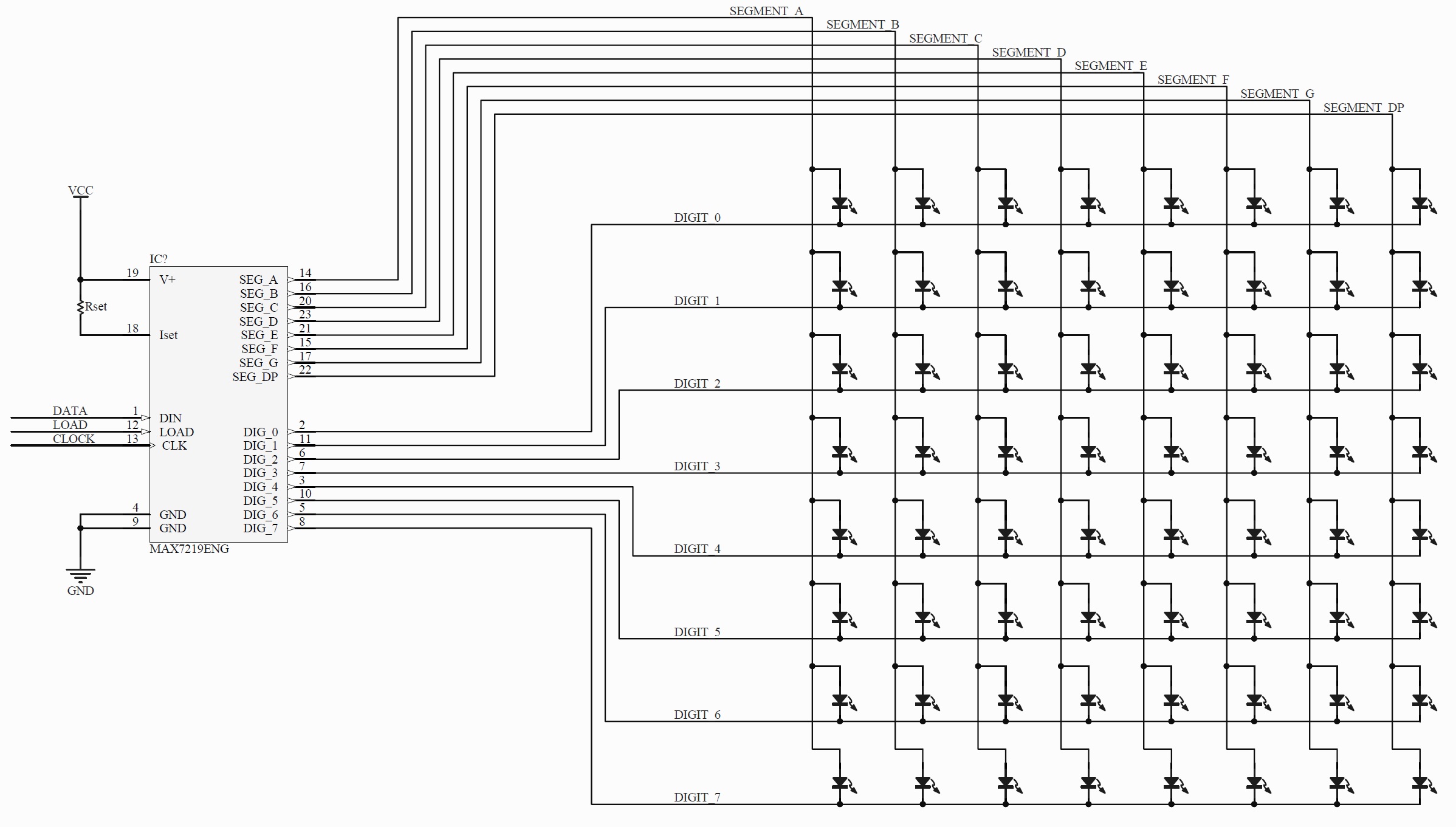
Here's a schematic of how discrete LEDs are connected in a fully populated matrix. You may leave any of those spots vacant without having any complications. Note: in a schematic, wires remain isolated from each other even if they cross, unless a dot (called junction node) is drawn where they cross. The fancy terms are mostly caused by integrated LEDs such as 7-segment or dot matrix modules. When 7 of them are combined within a single package, they'd either share a same positive pin (common anode), or a same negative pin (common cathode). But you can skip it all if you're using discrete LEDs. Here's a simplified version of what happens inside the MAX7219 if you're curious: It hooks only one of the eight DIGIT pins to the ground at each given time. It feeds current from the power to any combination of the SEGMENT pins at the same time. After enough time has passed, it does the same to the next DIGIT pin with a different combination of SEGMENTs. It scans 8 or less DIGIT pins in a loop at a rate of 500~1300 times per second so it's not observable to the naked eye. Normally you won't need to mind all that, just wire up your LEDs as in the schematic and Arduino scripts take care of the rest.
-
My engineering approach to a Hornet pit build project
Alex_rcpilot replied to Alex_rcpilot's topic in Home Cockpits
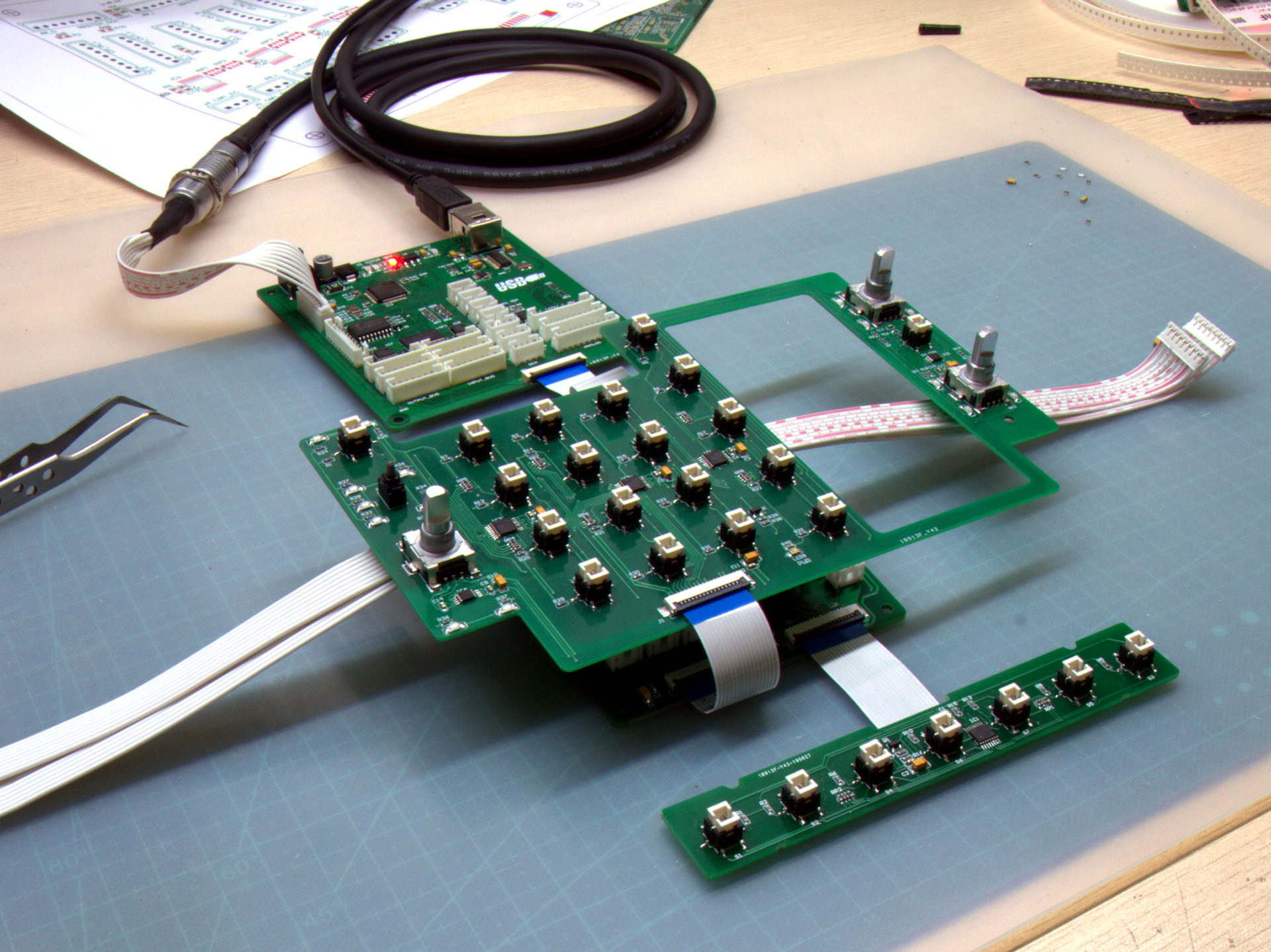
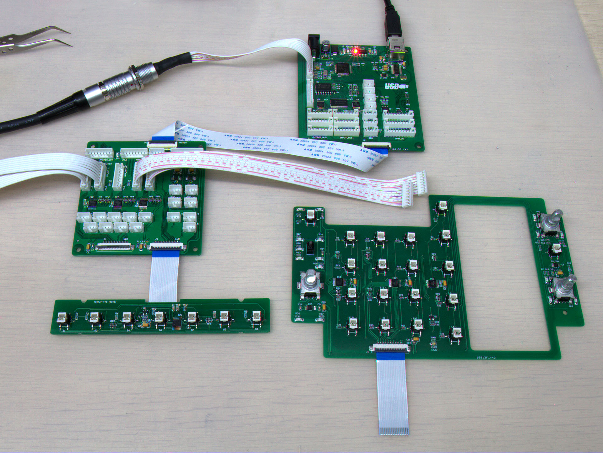
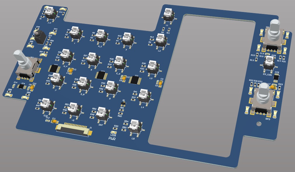
I've found some time to power up a few core modules for an initial test. The breakout card is hidden behind the UFC board. Most of the core modules are connected through FFC cables, while the peripheral cards will be hooked up with PH2.0 cable harnesses. Most of the mechanical structures have gone through several more iterations during the past weeks, I must finalize the design on those PCB housing before having the rest of the PCBs fabricated. Since the main controller card is already complete, at least I can start writing the firmware and use the UFC for some debugging.
-
My engineering approach to a Hornet pit build project
Alex_rcpilot replied to Alex_rcpilot's topic in Home Cockpits
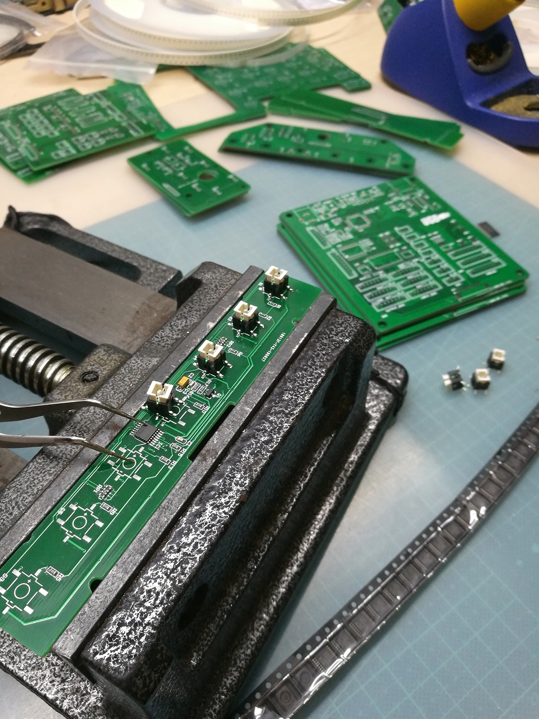
Got some of the PCBs fabricated. Soldering is also a time consuming task, but it's also the fun part.
-
My engineering approach to a Hornet pit build project
Alex_rcpilot replied to Alex_rcpilot's topic in Home Cockpits
Hi Wick. Thank you and it's really nice of you offering the footprint. I've looked up FSMIJ63BPG04 and found out it comes in a through-hole configuration. The one I'm using is a surface mount type, I could pick from a bunch of different colors for the LED when placing the order. I've drawn its 3D model as well as PCB footprint when I received it. And, yes, please feel free to build on top of my ideas. Hi Andy, I'm not planning on using 3D printing with most parts in this cockpit. 3D printed plastic parts actually cost more, and are generally less dense. Surface smoothness and lots of small details need to be sacrificed to get the desired strength. I've printed plenty of parts with different models of industrial 3D printers and sometimes experimental SLA printers. Frankly they are not my first choice for a densely populated instrument panel with sub-millimeter features everywhere. There are a number of conventionaly processes and materials at my disposal. However, I'm still in the designing process and haven't decided what specific process to use for each part, but I will soon reveal the results of my actual build. -
My engineering approach to a Hornet pit build project
Alex_rcpilot replied to Alex_rcpilot's topic in Home Cockpits
Hi, Andy. I'm using a 6x6mm tactile switch with an LED in the middle. I tried looking for an official model number or mfg info but couldn't find any. All the sellers just keep calling it the way it looks. For the DDI and AMPCD button caps I couldn't find anything off the shelf that resembles them, so I've decided to custom build them all. -
Advice on using LED's for warning light panel
Alex_rcpilot replied to lesthegrngo's topic in Home Cockpits
The LED lights up when current enters the anode and exits from cathode. Built within the MAX7219 are 8 high-side drivers and 8 low-side drivers. The high-side drivers can only "source" current from power supply, and the low-side ones only "sink" it into the ground. They are hard-wired in the ASIC and cannot swap functions. So it can't be applied to a 4x12 matrix. If you need 48 LEDs you may use 6x8 matrix. If for some reason there has to be 12 columns then you may cascade two MAX7219 in series so they support a maximum of 8x16 matrix. -
Advice on using LED's for warning light panel
Alex_rcpilot replied to lesthegrngo's topic in Home Cockpits
LEDs are sensitive to current which is non-linear in relation to the voltage across their leads known as forward voltage commenly written as Vf. A slight change in Vf sometimes results in significant changes in the forward current which causes either visible drops in brightness or the LED being fried. A resistor on the other hand is linear and helps "soften" the impact on voltage fluctuations. To calculate the ideal resistor value, use the following equation: R = (Vcc - Vf)/Id where: R: resistance Vcc: Supply voltage Vf: LED forward current Id: Expected LED current. Typical Vf at 20mA for different colors: Red: 1.8V Green, Blue or Whilte: 3.2~3.4V Actual voltage is negligibly lower at lower currents. Most Arduino boards are 5V systems, so Vcc = 5V. A typical Arduino I/O pin allows a maximum of 40mA. Maximum total current through power leads on a single chip is 200mA. (using ATmega32 as example) For me in most cases where brightness is required, Id = 5~10mA. (uncomfortably bright when looked directly into) The larger the package, the brighter the LED, even running at the same current and same voltage. Absolute maximum ratings for forward current is typically 20mA. An indicator LED looks bright enough at 5mA, it doesn't get significantly brighter when current is further increased. But based on our observation statistically, long term failure rates start increasing when current exceeds 15mA. Example: Green LED at 10mA. R = (5-3.3)/0.01 = 170ohm. Use 200ohm instead, actual current ends up somewhere around 8mA. -
My engineering approach to a Hornet pit build project
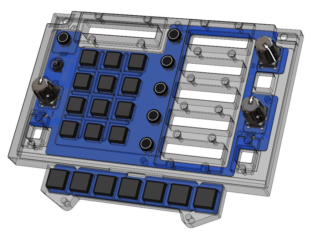
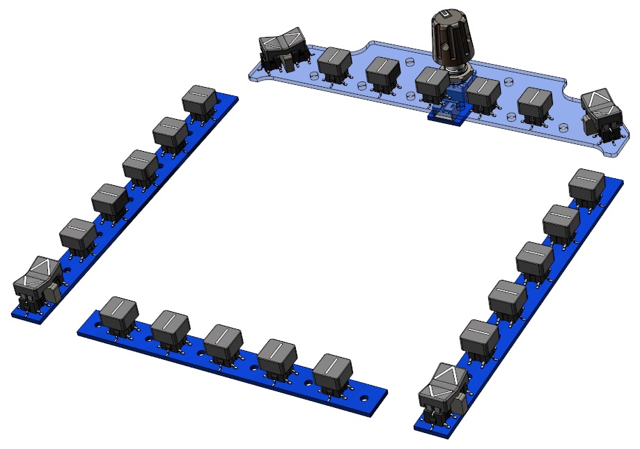
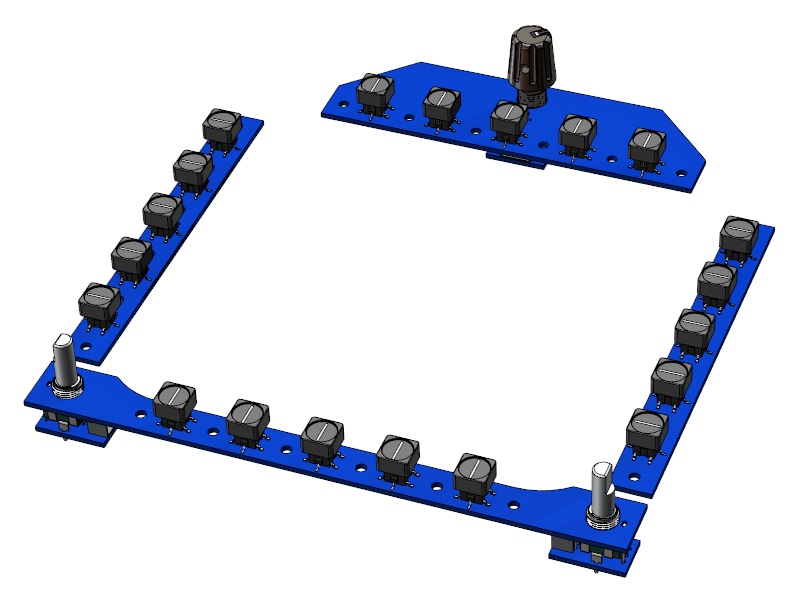
Alex_rcpilot replied to Alex_rcpilot's topic in Home Cockpits
Hi RK, I've followed your A-10C pit project and it's a fantastic build. I wish I didn't give up on mine. The Hornet is not a mono screen-friendly pit to start with. Customizing home cockpits is virtually all about trading off authenticity with cost. You've been there and done that, and I think you know it better than I do. Anyway, I hope I can complete this project soon so we may find out more about its potentials. And also thank you guys for your interest. I am determined to get this pit made fast, and please rest assured this project will move ahead steadily. Enough has been written about how the 3D model became the way it is. And at this point I feel like sharing some news. For the past week I've sourced a whole bunch of components like switches, encoders and potentiometers for screening. New packages are still coming in as I'm writing this reply. The best candidates have been thoroughly measured and modeled for virtual assembly. This time I will be using off-the-shelf switches for almost all the instruments and panels, which will significantly reduce the overall cost. But in order to keep the overlay material on top of the screen as thin as possible, certian degree of customization still has to be made. Using the new models, I was able to add more details into my 3D modules. All the pushbuttons are based on the same model, the only difference would be customized caps. I've tried soldering a whole bunch of wires in a cockpit and it was a major pain in the butt. So I've decided every toggle and pot needs a small converter PCB. I'd rather source extra wire harnesses than having to confirm what each wire does before soldering it to a lead. Ordinary sized selector dials and pots are too thick at the base to be soldered onto the same PCB as those tactile switches. Converter PCBs help get the job done. The standby instruments are more slim than most other modules while still requiring fully functional knobs, and some low-profile solutions have been devised for that porpuse. The next step is to re-model the base of the MIP screen mask so drawings can be exported for factories to start milling parts or bending sheet metal. I'll log back in another couple of days with more news.
-
My engineering approach to a Hornet pit build project
Alex_rcpilot replied to Alex_rcpilot's topic in Home Cockpits
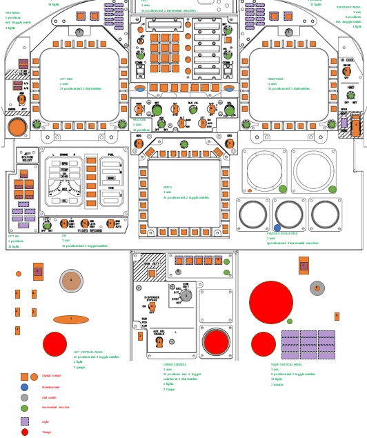
Thanks and feel free to adopt the ideas. I'm building my pit slim because I also work with this rig a lot and often fill the desktop with all kinds of crap. Racing is also fun but my G25 has been on the shelf for some months, haven't found time to play with it lately. I ran some numbers on the MIP and found that I need at least 17 axes and 230 button inputs for the front deck, it means I need to divide it into up to 3 different USB controllers. The way I count inputs is somewhat different from how the physical pit is perceived. For switches which each only requires one electrical contact but shows up in DCS as two positions, I will treat them each as two inputs. Some unconventional components are treated as even more inputs. There's a module in my firmware specifically written for this purpose. A quick count can be done on a single Word page: 3 physical USB controllers are hooked up to a self-powered USB hub from behind the MIP enclosure. Power from the hub's supply should be sufficient for all those back lights. The monitor has its own PSU, which means there should only be three cables sticking out from the back if I'm not missing anything. Although the MIP appears to be leaning against the desk, it's actually capable of supporting the entirety of its own weight. The rack is detachable, and when it's folded it can be stored in a cabinet, on the attic, or simply leaned against the wall. I will reserve, if I may, the following section of this post for some latest pictures as progress updates so new readers would immediately know which point I'm at without having to jump around in future pages. Progress quick peak section (images updated randomly reflecting latest progress) ━━━━━━━━━━━━━━━━━━━━━━━━━━━━━━━━━━━━━━━━━━━━━━━━━━━━━━━━━━━━━━━━━━━━━━━━━━━━━━━━━━━━━━━━━━━━━━━━━━━━━━━━━━━━━━━━━━━━━━━━━━━━━━━━━━━━━━━━━━━━━━━━━━━━━━━━━━━━━━━━━━━━━━━━━━━━━━━━━━━━━━━━━━━━━━━━ One of the 30+ PCBs which I've been designing for the past week. Center portion electronics Acrylic panels Backlight preliminary test UFC coming alive Prototype MIP and Lower console sections Supercarrier approach under the setting sun, June 26th, 2020 :pilotfly:
-
My engineering approach to a Hornet pit build project
Alex_rcpilot replied to Alex_rcpilot's topic in Home Cockpits
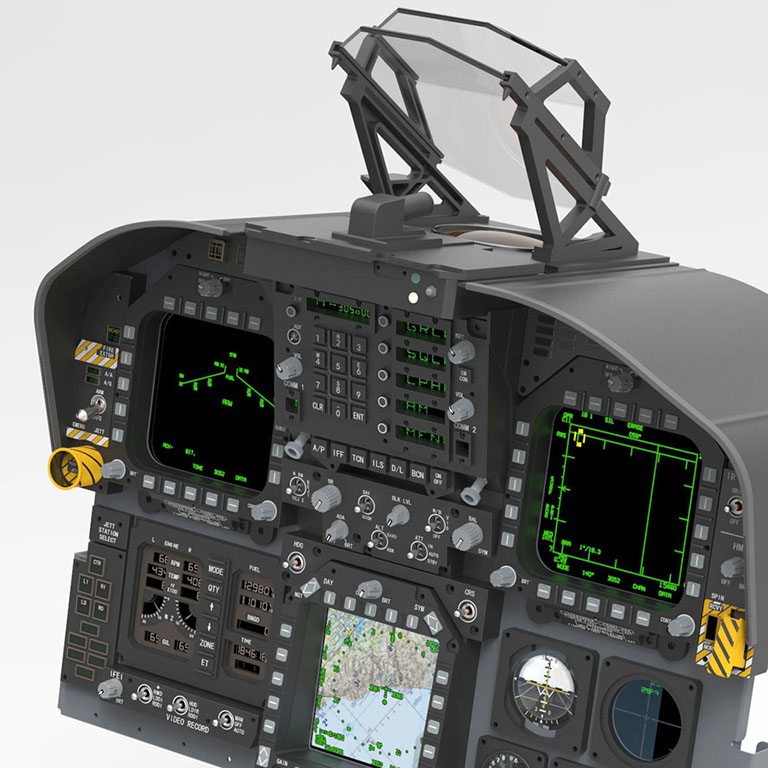
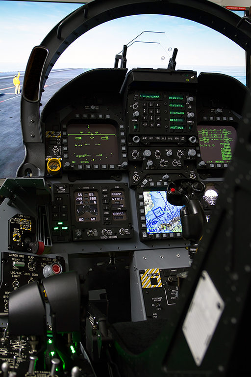
Great to have you guys here. I only do what an engineer does, and business is my friends' part. For now I'm focusing on getting stuff built. If this project turns out to be desirable then I'd love to see more fellow gamers flying with my design. More info on the plans: Unlike some of the high fidelity projects I've worked on, this home pit is born to be a low-cost design. The real MIP is not only divided into six sectors, but also done on multiple depths. If you take a look at the photograph by Thebeev, those DDIs stand out from the IFEI layer by at least 8", obviously to make room for the knees. The AMPCD also protrudes from the base plate for easier finger access, but you don't want it as high as those DDIs coz then it would get in the way of the stick. It'd be damn awesome to adopt this ergonomic structure at home, but just the displays alone would add significant workload on both the peripheral and the computer side. I'm already running 4 monitors on my desktop and don't want to stress it by that much. It also costs way more cash and time to source separate LCDs and come up with solutions to conceal them behind adjacent panels. That's why I'm going with just two displays, one for the UFC and another for the rest. First step of course is to determine screen size. I had to cross reference lots of sources available on Google and come up with a rough estimate of how big the front deck is. TBH the geometry of the glare shield has made it a tough task for a glass pit solution. In order to keep those top corners of the monitor concealed I had to give up the idea of using Helios for the caution lights beside the UFC. Turns out a 28" monitor is just right to span across the left DDI and the SVVI, which also covers all the core instruments except for the UFC. The gear & flaps indicator lights have to depend on standalone electronics instead of borrowing pictures from Helios. If compromises had to be made for the UFC they'd better be worth it. So far it seems fine. I mean look at how the HUD base sticks out from the top edge, having the UFC elevated from the monitor's face level both solves the display problem and makes the geometry more "layered", all at the cost of one small additional display. Once I've picked the essential parts I could start designing the sheet metal enclosure and face plates.
-
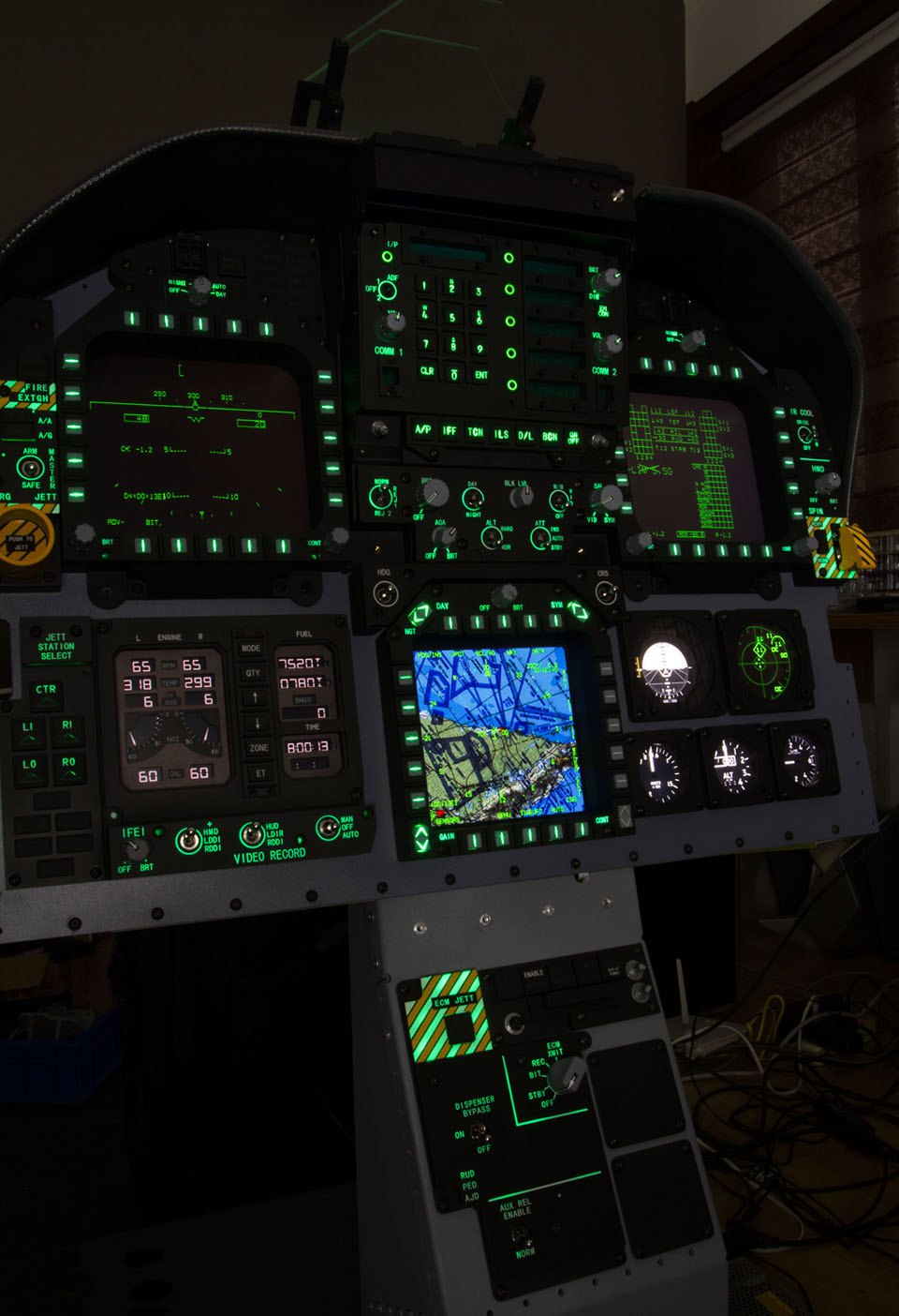
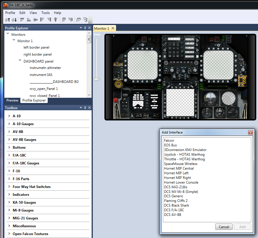
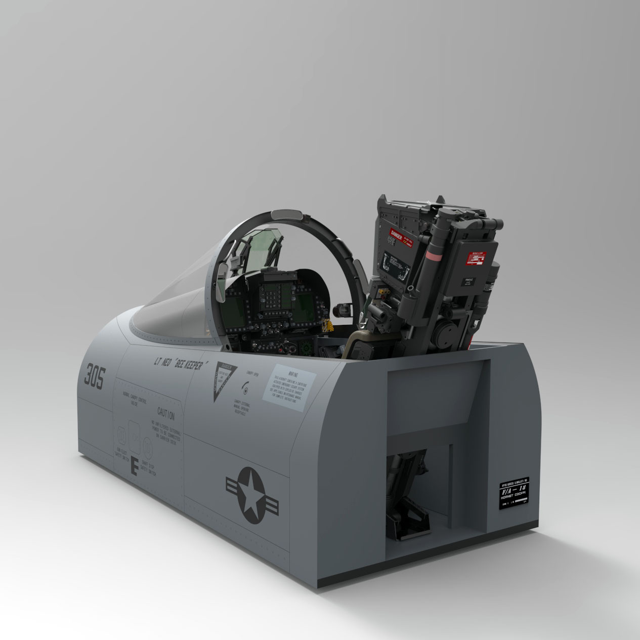
*Latest Edit: Now there's a site for this project and future projects: https://www.neoengress.com/ I've been wanting to do this for so long that I'm actually feeling a bit over-equipped. When the hog came out back in 2010 I almost went for a full pit. But plans grew too lengthy and life got in the way, I had to quit it. Now after creating a diversity of peripherals for other people, I finally got to take a break and start building something for myself, something practical and less complex than a full pit. The stuff I'm about to reveal in this thread is some work in progress for the past few months. I'll first present some background info on how I approached it in the first place, how it gradually came to this point, then keep you guys updated with some latest development if this looks compelling to you. I'll skip the obvious pros and cons of having a physical pit, and just lay down some of my priorities real quick. My goal is to build a physical pit (sort of) which: has both input and output capabilities; doesn't cost me my quality lifestyle to build; still looks sufficiently badass and attractive, at least makes my girlfriend jealous for having my company during day time; fits in a tight space against an ordinary computer desk; comes off and stows easily when not used; can be built one module at a time, each self-sufficient as a human interface device; works with both conventional monitors and VR; helps refine my engineering skills, inducing massive pleasure during the process of creation. Like every 15 year+ flight simmer I'm already in possession of....you know the ordinary cliché, the first item on my list would be the main instrument panel, followed by the Martin Baker ejection seat and more. Here's a preview of my current front deck 3D model: I took my time and modeled every component to the details: Since I need those instrument outputs like the UFC and MDIs, this project is generally built around an LCD monitor taking advantage of the DCS legacy viewports. And for the standby instruments I'll just use Helios, Craig and Capt. Zeen have done a great job with it. Turns out a great percentage of the MIP is covered with inputs, all of which I intend to make as functional, that's over 200 inputs scattered across 2 square feet, lots of which are encoders. Some of the indicator lights spread beyond the monitor's active area and also require dedicated hardware support. Now I do have a bunch of Arduino boards lying around in my drawers, but for something this compact and requires certain performance, I'd prefer making my own USB electronics from scratch. I use professional EDA tools and high performance microchips on a daily basis, so it won't be an issue for me. With all the parts and efforts involved, there's a subtlety to the balance between cost and quality. I've been in the engineering domain for a long time and a great number of suppliers are also my friends, who offered to help me build fun stuff. Since this is gonna be my own toy, choices will be made based on all the resources I can get here. I will try my best to make some of the designs also compatible with 3D printing so I can share the stl models which enable others to join. Nevertheless, my attention must still be focused on making RAPID progress. I should be able to post more stuff here every now and then. For now, I hope you guys liked the idea of it. ----------- Update by late June 2020 ------------ Phase 2 - Expanding into a full pit It took me eight months to complete the MIP section which was "something practical and less complex than a full pit". All the displays and inputs were working. Before this project, it always felt like so inefficient having to freeze my head tracker before clicking on those MDI buttons. The physical MIP came in as such a big saver for in-flight ops. However, with the release of the super carrier module on the horizon, a pair of vertical panels felt more and more desirable for me. These panels are likely the most densely mechanized areas in the pit and certainly deserve some serious design hours. Besides, with the help of my friend William, more and more SJU-17 parts kept coming back from the factory, the ejection seat was also starting to take shape. I sourced a couple of electric cylinders so the seat can be easily adjusted by the touch of a switch. I see only one toggle switch by the left side of the seat in game, probably for height adjustment. I'll add a second one for an extra feature. The second phase started back in Feburary with the design of the gear handle and wing fold handle. It gradually grew across both vertical panels and then expanded further back to cover both side consoles. By the time of this edit most of the parts for the second phase have arrived, the vertical panels have been fully assembled and I'm ready to assemble the rest. New pictures should be available in the next few days as things are gradually put together. ----------- Photo of latest progress ------------ A more realistic design is also ready, for skin and livery lovers:
-
Hi Capt Zeen, nice to have your reply. Now it's working great thanks to your reminder. Yes I made the download directly from your site when I Googled for a SU-27 solution. I also experimented with Gadroc's scripts. I'll explain later. Turns out I missed out the IMPORTANT NOTE on the top when I was all focused at scrolling down to find the SU-27 profile in the first place. And yes I used the Export.lua that came with the package. No wonder the notes are IMPORTANT:doh: It also turned out that I set up the wrong UDP client with my socket tool. I thought DCS created a server at 9089, while in fact the client itself has to be set on port 9089, not try to listen to 9089 from some random port. That's why I wrongly concluded that the function never got called because the socket tool didn't hear anything. I was quite good with this export thing when I created my own Export.lua and VC++ program. But it's been 7 years since I did that, and I didn't leave any documentaion for know-how. Lessons learned, I'm off to archiving. Thanks for the help Captain.
-
BTW, the log file was only used to check if the .lua has been called and executed. I've also checked UDP connection at first. Helios was not getting the data. I used a socket tool and opened up a UDP client at 127.0.0.1, listening to port 9089. Found no activity whatsoever.
-
Hi, I haven't flown for some time. Export.lua used to work in previous versions of FC and DCS. Now I can't seem to get it to work. No idea whether it's got to do with DCSW2.5 upgrades. Thing is, I have to determine whether the file has been executed when the game is running. As long as I could remember, there didn't seem to be a switch anywhere else where you need to tweak a line to enable Export.lua. So I think I just need to place the file in the right place. I'm aware that the Export.lua found in DCS World 2 OpenAlpha\Scripts\ is just a sample template. I've downloaded the Helios version and Capt Zeen's version of Export.lua, and put them in both these folders: USER NAME\Saved Games\DCS.openalpha\Scripts USER NAME\Saved Games\DCS\Scripts Note: 1. I don't think the latter one works since DCS.openalpha is the active path for 2.5. But I put it there anyway because the template still says you need to put it there, wouldn't hurt anything. ED may forgot to upgrade the template though. 2. I've created both Scripts\ folders manually. In order for the scripts to leave a trace, I've modified the log file open command within function LuaExportStart() , now it looks like this: debug_output_file = io.open("E:\\ExportDebug.log", "wa") debug_output_file:write("Error log begins.\r\n") The absolute address is just for convenience. I suppose if export.lua ever gets called, it would leave a log file behind, even just an empty one. But no matter where I place this file, there's no sign of a log file being created. So I'm a bit confused, is there a hiden switch anywhere else that I need to turn on so that export.lua gets called? I have to know it because then I can decide whether I sould focus on the stuff within this particular file or outside of it. Thanks.
-
Not exactly. Only potential problem would be nonlinearity on the stick position v.s pot angular position curve, if any.
-
Ferrite beads are used to block off high frequency interference. It's rated primarily by impedance at 100MHz. So when you talk about a 50ohm ferrite bead, it means it has 50ohm impedance at 100MHz. Ferrite beads have current ratings, but they are not designed to fail at certain current values. A bead may hold up quite a while even with currents higher than rated flow through it. How fast it's consumed in a blaze depends on how strong the current is. It can't be used to guard against excessive current, because when it burns open, whatever else is on the short circuit path is probably equally fried. On the other hand, a fuse is rated by current, and it has to blow immediately after power flowing through has exceeded its rated value. Visible fire may may appear when the fuse blows, leaving smoking residue on the PCB surface. I don't know what they did put on the board, but it looks like a fuse to me. Finding a proper replacement requires removing the broken part and measuring actual current consumed. Adding something around 30mA to the measured max value, then you have an a rating number to begin with.