Alex_rcpilot
-
Posts
547 -
Joined
-
Last visited
Content Type
Profiles
Forums
Events
Everything posted by Alex_rcpilot
-
Seems like nobody is willing to test it. I think I gotta purchase a beta version and confirm this issue. And then report it as a bug to ED. Damn I like the DVD version instead.....
-
Has this problem been confirmed positive with A-10C? Anyone?
-
In order to report this issue I have yet to confirm it because I don't have access to the beta release for now. If someone with the software may spare some time and do a few tests, please either post your results here, or directly report this issue to ED. You might wanna also put up the link to this thread to save a lot of elaboration.:)
-
lol, yup, but no problem. Have you tested any of those rotaries with the default config on your keyboard? :)
-
Guys, now that Warthog Beta versions are available, has it inherited this issue? I have yet to wait for a couple of weeks before I get the money for pre-purchase. I'd like to bring this problem to ED's attention because it's going to dramatically affect the way peripherals are built and their performance. Hope someone will look into this matter if it's not too much trouble. Thanks!
-
Yeah, it's an innate defect for VFD's, the clearance is built to house wiring. I'm desparately searching for an OLED that will fit. No luck at the moment.
-
I've ran out of ideas for the EWMU display. I guess I shall lower my standards just a little bit to save my pocket.
-
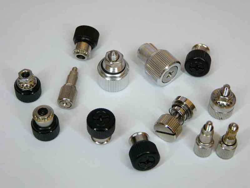
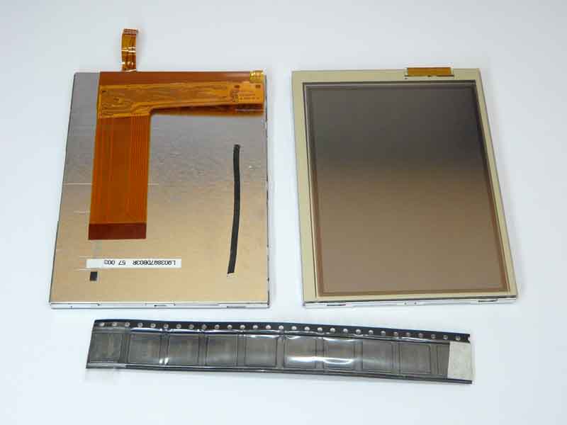
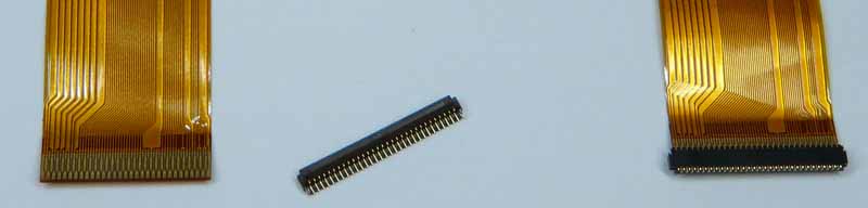
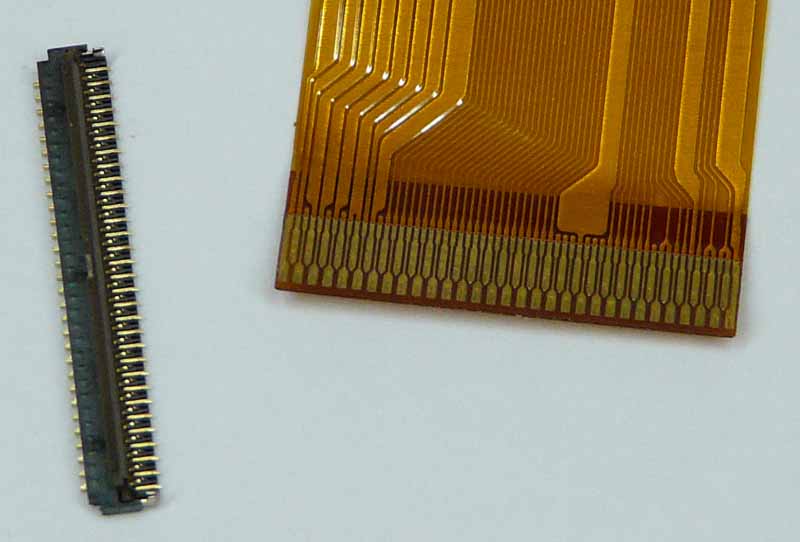
I figured even if I got ahold of some DZUS fasteners, I would still have too much trouble with receptacle strips to continue with. So I set off seeking for a tradeoff. These are the closest I could find, but I guess they're temporarily useless for me as the screw heads are simply too short: And these are the rare 3.8" TFT screens from Sharp that will be used in my CDU(couldn't disclude touch screen when I bought them): Chips at the bottom are from Samsung, and they're dedicated to drive gate-driver-less 240*320 TFT screens. Finding a connector for such type of FPC is a pure agony. Yet I managed to get it. There're still some chips on the way. I'll be able to design the hardware for both 3.8" and 3.5" TFT's. I will post more progress when it's available.

-
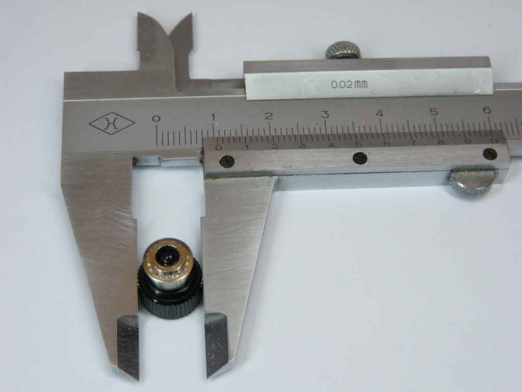
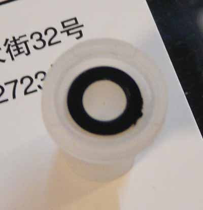
I guess now I can be certain with transmissive buttons. 'cause I found this yesterday: That's a conductive rubber ring, and I can put an LED inside the cylinder space within.:)
-
Oh man you're gonna have so much fun.....at least I can promise you that. lol! I check the Teensy board before searching for Arduino. It must have taken the author quite some time to develop Teensy because the AVR used on his board doesn't have a built-in USB module. He did it by simulating the exact USB waveform and implementing the USB protocol with two GPIO's. You may use SPI interface to establish highspeed synchronous communication between two boards, and it's quite interesting. And if you have problems regarding these boards, I may be able to help coz I had been using AVR with my projects for years before they ran short on supply in China not long ago.:)
-

Nvidia SLI performance for DCS and LO comparision
Alex_rcpilot replied to G3's topic in PC Hardware and Related Software
I'm using SoftTH and it works great for single player even with older driver versions. Problem with multi-player mode is the server selection menue will span across all three monitors, and only the center monitor area is clickable. I even had to bring up task manager to exit that screen. -
Cool! Can't wait to try it on my rig.
-
Hi guys, a major advantage which USB HID has over "backdoor" access is responsiveness due to DirectInput (a component of DirectX) support. LUA export updates once per frame, and I don't know how long a frame takes, perhaps it's a variable period which is not considered real-time. So if you wanna hook up pots / hall sensors as stick inputs, or if you'd like sim functions to respond to your button press with no lag when split second counts, you definitely wanna use USB HID. to Dantx101: The Arduino Mega board looks neat. But it's not capable of being configured as an HID because USB connection is handled off the microcontroller by the FT232R, which is an application-specific IC designed as a USB CDC class device. However, you might be interested in PanelBuilder's solution which involves LUA export also through a virtual COM port. A software running on the PC channels the LUA socket with the virtual COM port, making it possible for your ATmega1280 to directly receive the exported data. all you have to do is parsing it. Did you also order an ICSP programmer? If you did, you may use IAR or CodeVisionAVR to write firmware in C language, or use AVR Studio to develop it with assembly. Good luck.:thumbup:
-
BTW, a 3.5" TFT has a display area of 2.76*2.07", which will look a little guly when fitted into the CDU window.
-
I wish I could be certain, but it really depends on want we want them to be like. If we're talking about silicone, then I might be in for it. I will try to have some made, but first I need to verify some dimensions. lol, having lots of factories around certainly has some advantages when it comes to pit building or stuff like that. But there's also a downside to this. I think we all know what that is. wow this goes far beyond my initial thought. I was thinking about using smaller conductor pads and solid rubber pads, and putting LEDs beside them, which for sure won't be sitting at the center of the buttons. I guess they could do better because they made conductive rubber rings instead of pads? I do remember the guy from the silicone company mentioning something like backlighted buttons, don't knwo exactly what it looked like. But I'll have this figured out next time I pay him a visit. VFD was simply too expensive for me. As I later added, one piece at the right size would cost up to 75$, I simply grabbed a cheap LCD module for 7.4$ and ran home. :doh: Besides, neither module provided enough space for the DSUZ fastner and the button right next to the display window. Still have to figure out a solution. CDU screen solution pretty much depends on how ED exports the text data. If they handle it like they did with ABRIS, then I'm toasted. At this size, it's very difficult to find a TFT larger than 480*320, most modules are 320*240. For a display to work as an external monitor, it requires a minimum resolution of 640*480. So I'm going with probably the only solution, which is using a microcontroller to generate a visual text UI. The controller also accepts a text data feed, which could be one or multiple of the following options: ethernet, USB, RS-485, IIC... Personally I will put USB and high-speed RS-485 on my board. Size of the screen has been a major headache for me, no s**ting, it really is.:cry: If you look at data from various sources or take measurement from the screen shots, you will see that the window size is so wrong for off-the-shelf TFT's. Data from the internet shows the screen size is 3.25*2.60". And screenshot from ED shows a very close size of 3.25*2.50". I went with the latter result, And found it extremely close to the active area of a 3.9" TFT. The text area however, doesn't take up so much space, and a 3.8" TFT will also do the perfect job when its steel bezels are properly concealed. Then I started searching for distributors for two weeks and hardly found any company selling 3.9" TFT's, I was lucky enough to have bought two used 3.8" 240*320(portriat) PDA screens whose display areas were 3.15*2.36". But the ordeal was far from over. The FPC connector was a kind of high-density 0.3mm interlaced 61pin component. Each tiny connector alone would cost nearly 6$. Yet there are many strange signals found in the datasheet which are very much unlike regular TFT's. As a contingency plan, I ordered a 3.5" TFT yesterday. If stuff don't work out with the 3.8", I'm gonna have to scale down the text a little bit to keep the project running. By then the CDU will look disproportioned, but that's the best I can do. I think we're both hoping someone with definitive data could magically show up and generously offer some critical dimensions to help us make this unit more accurate. In my drawings I've made the button caps and the frame stick out 2mm(approx. 1/12.7") above the panel surface. As I can't get ahold of polystrene plastic stripes, I will probably have them sliced off from the side of an acrylic sheet, and somehow glued and painted.
-
Hi, I'm also going to build the CDU panel. My plan is to have a factory make all the buttons on a single silicone sheet, like what you'd normally find inside a calculator or TV remote. They can make the characters on top of each button transmissive. And I will use gold plated traces (button pads) beneath the conductive rubber pads at the bottom of each button cap. Take a look at the back of my panel: I have two options: A. Arrange one ultra-bright LED beside each button pad to light it up from inside. B. Engrave shallow slots along the dividing grids of all the buttons and embed EL wires in row and columns to form some shining grids, illuminating the lower transmissive halves of the buttons and making them glow. Anyway, what does a CDU with back lighting on looks like? Are we missing some parts which should have been lit? What type of display are you planning to use for the screen? I'm working on a 3.8" as well as a 3.5" TFT with a bunch of electronics. I've also noticed the frames around the alphanumeric areas, I thought those were just white stripes painted on the surface. How high are they? Thanks.
-
Ok, now I get it. 1/4" is pretty thick for an acrylic sheet, but considering the height of the screw head which are better off hidden beneath the surface of the panel, I'd say it's just about the right thickness. I didn't look for screws like those on purpose when I went to look for VFD the other day. But as I took a glance, it seemed difficult to find one of those screws here. So far, the best way I can come up with is screen printing. It requires a stencil and I don't think you have to DIY. Many companies from many countries provide such services. I talked to a local company, and they told me that they could do just about anything on the acrylic surface for a pretty low price and minor quantities. As I stated a couple of replies back, the only thing that bothers me is that they don't print around the edges of the panels. If you print them yourself, you'd get some of those ink, at least a similar type, and try to get it done for yourself, I guess it will be difficult to smoothly blend your ink with the perimeter of the previously printed area. I'll keep looking. Alright, there's another issue I'd like to seek some help about. Has anyone heard about or felt the CDU buttons for himself? How do they feel like when pressed? Talking about the feeling on the fingertip, is it something a little bit tender like the silicone buttons on a TV remote control, or something brittle like the left/right mouse buttons. And I'd consider a regular keyboard as something in between - silicone inside but gives you a clear feeling of up or down position. I'd like to mimic this characteristic when I build my own CDU.
-
Well, it doesn't necessarily take an electric drill to make that point, but it could be fun to demonstrate how reliable your system is in this way. Basically if you're pooling the pulses from the encoder outputs with a regular routine, it all depends on how frequently you poll it in your s/w. If you turn the encoder fast enough so that more than one states make their way into the time slot of one polling interval, your program will miss some pulses and generate false results. And if your program interrupts on edges, you're likely to get better response out of those encoders. But there are still chances that the encoder spins fast enough and overlapps the same interrupt causing problems. I guess you already knew most of what I said, but it's difficult to calculate how long the maximum time is which takes the program to run between two polling routines. Personally, as long as it doesn't go haywire when I spin it as hard as I can, I can live with it. :) Regards, Alex
-
Hi y2kiah, despite that you said "The actual material will be a single piece of acrylic", I'm still a little confused about the apparant sandwich configuration seen in your first picture at the top. Because it looks like it has back lighting, and that there could be an EL sheet between the top and bottom layers. I've only asked this question because those six srews along both edges won't have any effect with the top and middle layer unless they are glued to the bottom layer. Or did I figure it wrong and they were one solid piece of acrylic. Were you actually going to attach an EL sheet underneath the entire piece?
-
DCS A-10C producer notes number one!
Alex_rcpilot replied to kingneptune117's topic in DCS: A-10C Warthog
I wonder whether the incremental rotary has been enhanced for keyboard input (repeated) in this sim. -
Hi y2kiah, I found some dealers who are offering silkskin services for panels. The yellow stripes won't be a problem for them. What bothers me is they can't paint the edges of the panels. I guess I'll paint the edges for myself at some point, either before or after handing over the rest to them. I'll keep looking for more options.
-
Well, I'd vote for the latter - use some sort of hollow cut and spray paint. But it's also likely that I'll turn to some kind of factory for help. They manufacture panels and they have the right silk skin equipement. Allegedly it doesn't cost much, I'm gonna have more information when I come back. Gotta go.
-
:thumbup: No probs. I use Solidworks. Default materials are limited, and I have to create texture to render my parts, which is also an overwhelming job. Anyway, how do you plan to paint the stripes onto the actual acrylic panels?:)
-
Hi, y2kiah. How do you manage to paint the yellow stripes with precision? BTW, your software renders pretty well, it looks nice.
-
I guess those are relatively dedicated LED's, they don't sell much of those and the price stays high. Try to look for Vacuum fluorescent display(LED), or organic LED(OLED). Like LCD, when refered to as "dot-matrix", it usually comes in no more than two solid display areas filled with uniform matrices of pixels. On the other hand, alphanumeric display are quite like segmented display. Pixels are divided into individual groups, each with a number of pixels arranged in a pattern depending on the character they are capable of showing. Pixels may differ from each other in shape, and they are designed that way to make the characters look smooth and confortable. In between, is characther display. It looks like alphanumeric display in character arrangment, as pixels also come in groups. But within each group, it looks just like a dot-matrix display which has uniform pixels. I'm headed out to visit electronic stores, hopefully I may return with a character VFD in the right size. :music_whistling: