Alex_rcpilot
-
Posts
547 -
Joined
-
Last visited
Content Type
Profiles
Forums
Events
Everything posted by Alex_rcpilot
-
Hey thanks for the link, they've got some really nice stuff there. I guess I'll stick to my plan and utilize a character VFD module. It just takes the release of the sim for me to interface the hardware with the virtual aircraft. :pilotfly:
-
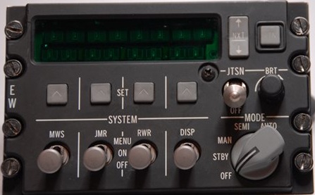
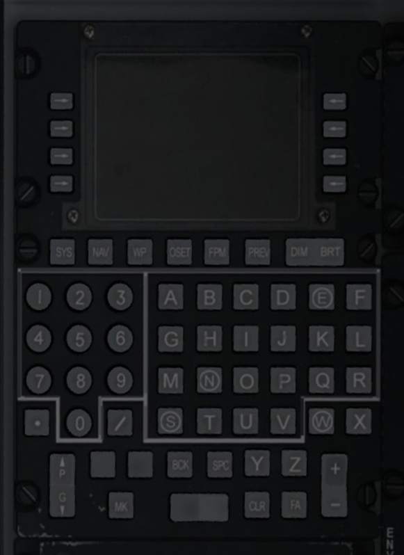
Good work, y2kiah. I've started with the CDU panel on the right. The width of each unit is 146mm, just 0.5mm narrower than yours. Then I spoted the EWMS which is pretty interesting. It's probably the only VFD screen throughout the entire cockpit. If I have no luck finding a similar display, I might turn to 20X2 ASCII VFD components. Is it possible to find a picture with the display active? I'd like to see how it glows.

-
oops, never had the pleasure to use OpenCockpits boards, but I'm having problem with my own solution as well. Hopefully someone with the right experience will show up later.
-
That sounds like a good reason for me to feel lucky about my dual-gigabit motherboard. lol
-
Hi Total, thanks for the tips, that's something I hadn't noticed before, I will keep an eye on them later. However, I don't think the type of physical component has any contribution to the problem under discussion here. Because: A. It's a timing sensitivity issue in the software which is made worse by the fact that Windows is not an RTOS (Real-Time OS); B. My hardware & firmware is custom-made which accepts inputs from literally any type of component, or no component at all (software signal generator). It generates a standard DirectX button input which is directly recognizable by DCS software despite the component being used. And no matter how precisely this input is generated, DCS fails to percieve it 100% properly, presumably due to the none-real-time nature of the OS. Accurate timing can't be achieved easily on systems like Windows, a virtual object like rotaries works better with an event-based response logic, rather than a time-span based one.
-
Oh thank you y2kiah for the reference material. Now I get the point. That's a pretty handy device, though I don't really need one for obvious reasons. lol.:)
-
Hi Napalm, thanks for the tips. I'm not quite sure what this switch looks like in the setup page, but maybe many people can work it out with their own routers. That question was kind of generic because I thought it might be the case for the majority of pit users. Personally, I'm lucky enough not to have go through so much trouble because my motherboard actually carries two gigabit ethernet ports. But I'll try n' mess with the router later anyway, just for fun...lol
-

GIDEI (General Input Device Emulating Interface)
Alex_rcpilot replied to PanelBuilder's topic in Home Cockpits
Nice, that should save some work of defining all those commands from scratch. -
Thanks for the info:thumbup:. Now before ED (doubtfully) optimizes this rotary function, the only way to handle it properly with a physical component is through LUA socket. I'm not sure if your interface board has its own ethernet driver, if it does, things are certainly straight forward; otherwise, you've presumably built a socket server/client software on the PC to bridge other types of communication to the LUA socket? Here's an interesting question: is it preferable to build the cockpit with ethernet port only or USB port only, or both? If someone with a computer whose motherboard carries only one RJ-45 connector runs into an ethernet-based cockpit, how does he manage to connect to the internet as well as the cockpit with the same port? Is a router gonna help? And if this pit was built with a high speed USB port instead, which relies on some sort of bridging software on the PC, will this software reduce PC performance by too much?
-
Sure, Cat. I can try that. But what it does is no different from changing parameters in my firmware. I've already tested my 'denser' rotaries notch by notch with an oscilloscope, not being able to spot any lack of positional response. The point is the design concept of these rotaries aren't compatible with keystroke inputs. I searched for articles talking about mice, and it turned out that the mouse wheels generate a "scroll n lines" message which doesn't contain any timing information. This's is unlike the button down - button up process reflected with buttons or keys. And that's why those rotaries work so well with mice.
-
Thanks for the reply, PanelBuilder. May I ask what type of message did you send to DCS? :music_whistling: I'm still immitating two standard joystick buttons with each incremental encoder. So my "message" is simply a standard joystick report handled by DirectX. As you said "it's nice that we don't have to", I presume you've found a workaround for this problem? As you've pointed out, knobs like ABRIS brightness adjustment are finite, I thought about it for a while, but still couldn't figure how finite knobs could take advantage of this timing-sensitive input style. Although there might be various workarounds, I still think it'd be better to optimize this slight detail in future releases if there's no obvious advantage with keeping it this way.
-
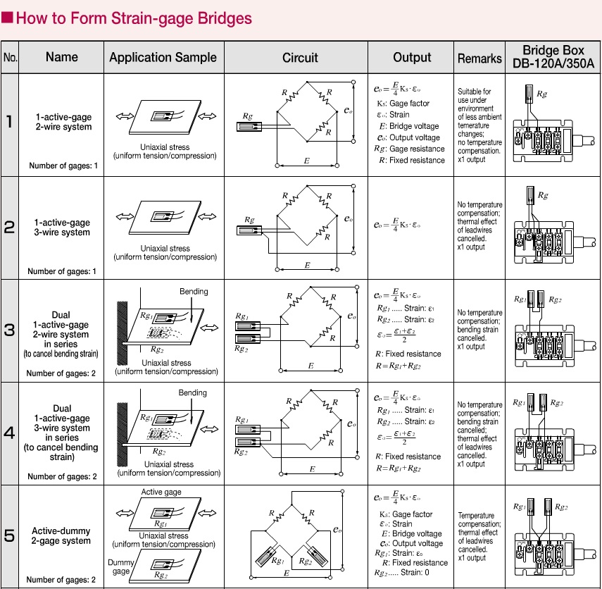
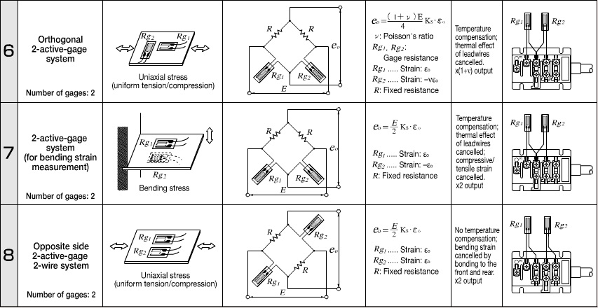
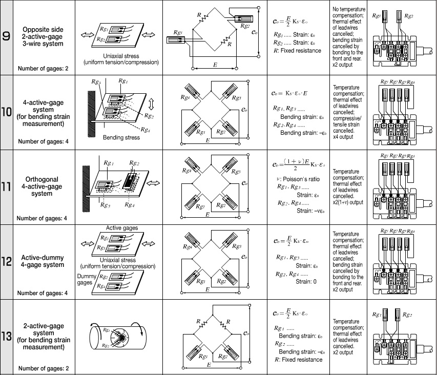
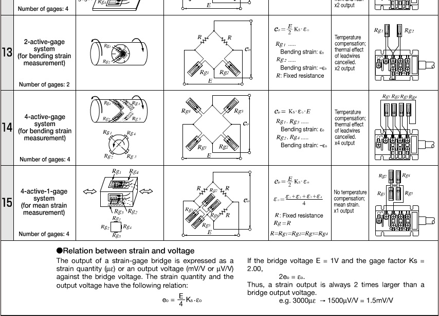
I'd be happy to convert sch into PCB layout for you. I wish I could design the sch for you as well, but I can't make that promise coz I've been multitasking for myself since the beginning of this year. :cry: You might wanna start with these strain gauge diagrams: I still haven't checked them thoroughly, but I think one of these examples will fit your needs. Once you've chosen the right configuration, I may find you some un-tested application circuits for you to test with breadboards. Can't test them for myself because I have neither the shaft nor the gauges with me.
-
At least Leo's board handles USB pretty well. If LegTaste has decided to use load cells or strain gauges, I think he'd also be interested in learning some skills with building analog circuitry. It only takes some differential amplifiers, resistor network and capacitors to convert physical inputs into 0~5V linear signal. Enjoy the process:)
-
BlackShark + SoftTH v1.09rc1 antialiasing issue
Alex_rcpilot replied to Alex_rcpilot's topic in Bugs and Problems
antialiasing=1 antialiasing=2 -
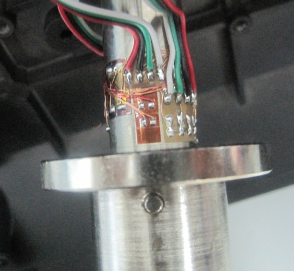
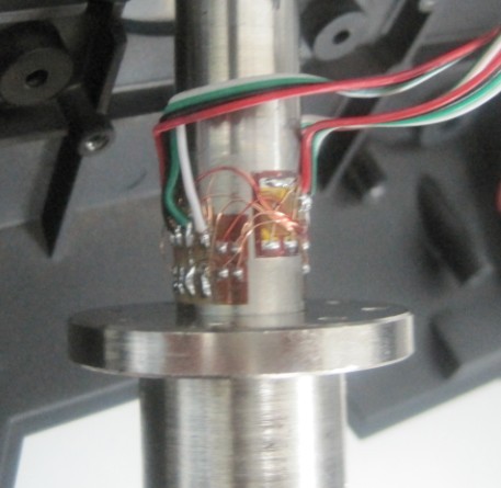
It'd be difficult to separate X Y and twist inputs with load cells. I hope the following pictures of the X65F will give you some more ideas. I got these pictures from 3GO*CHN-388. If it's possible for you to obtain load cells, you might as well have access to strain gauges. Try to search for different configurations with strain gauges, there are various circuits designed for X/Y bending and twisting measurements. Good luck.
-
Hi guys, have you noticed that rotaries only work well with the mouse wheel? Well let's say probably most people haven't tested them with keyboard or joystick buttons, but here's a chance to try it. And you'll find out that they not only respond to keystrokes, but are also overwhelmingly sensitive to the duration of the input. That means as long as you hold the key/button down, the rotary keeps turning. It's quite difficult to control how many detents it turns with each keystroke you make. At first I thought it might have something to do with axis, that ED might have had considerations on rotary usage with joystick potentiometers. But as I tried assigning an axis to a rotary, I failed. It makes sense that you can't turn a rotary with an axis because rotaries are normally meant for infinite rotation, while axises aren't. This is exactly what's puzzling me: A. Why are they built to be sensitive to the duration of corresponding inputs? I tried using precise electronics to generate stable repeating keystrokes with adjustable duration, but the rotaries either misses a couple of inputs, or turns too much. It's quite difficult for me to find a perfect duration for the button to be held down. I'd like to consider this a bug in my test rig. B. On the contrary, why is the mouse wheel so reliable? Is it because DirectInput sees mouse wheel input as an undividable directional "notch" event, rather than a "button down" event followed by a "button up" event which happens to buttons? I think it'd be much better if a rotary responds to a "button down" event by turning exactly one notch in the pre-defined direction. Then it ignores the following "button up" event, and stays there till next "button down" event. I hate to bring additional workload for the ED crew who are already working around the clock, but I'd appreciate any response from you guys. Perhaps you may consider my suggestions with the next DCS update. Thanks! :thumbup: Alex Young
-
Hey guys, I've been tweaking with my triple monitor settings after upgrading to Windows 7 x64. It works perfectly except that I can't use nVidia control panel to set anti-aliasing for Black Shark due to SoftTH restrictions. SoftTH v1.09rc1 has actually removed antialiasing scripts from its stock cfg file, but as I tried to migrate the following lines from v1.07: antialiasing=2 anisotropic=1 they appeared to have worked in game. It would have been fine if I could put in strings like 16xQ or "16xQ" or even '16xQ' as parameters. But unfortunately the only values that seem to have worked are 0(off), 1 and 2. With a value of 2, I'm getting noticable better smoothness than what I got with a value of 1. SoftTH suggests that the AA settings from graphics cards' control panels shall be set to use settings from the game, and set the desired values with options from the game instead. I've tried to forcibly turn on the AA from nVidia control panel but it was simply ignored by the game. Has anyone got further experiences to share? Anything help be appreciated.
-
Another great thread. Good job with the 3D model.
-
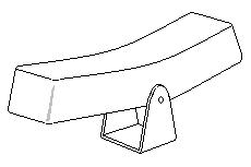
You may also take a piece of metal, slightly bend it to fit the curve angle of the rocker actuator surface. Wrap a piece of rough sandpaper around it to make a V-shaped file like this: Then you may cut a rectangular acrylic stick, and carefully file the top surface into a V curve. :)
-
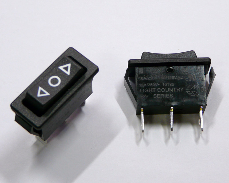
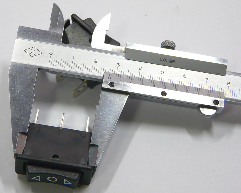
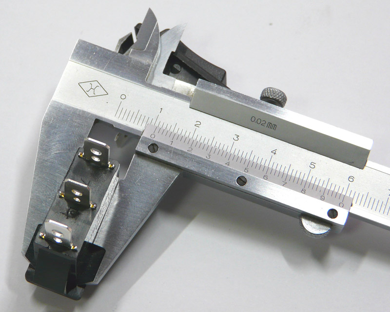
If you intend to stick the button out by 2mm, the button should measure 22.5 x 8.7mm. Yes you may remove the protruding edges around the casing opening. But with the hinge not far away from the edge, you might need to add some strengthening structure elsewhere to keep the side wall from bending or tearing. I suppose Light Country is the brand name. This rocker is made in Taiwan according to the dealer. A 20 x 8 actuator will certainly do the job. I think you may just cast it for yourself, or make it out of acrylic. Cut the curved surface with a mill, and then shape the rounded corners. Drill a hole in the middle and stick in a metal shaft as the hinge. Then you may build a support out of a piece of thick brass, bend the plate like a sitting bracket with one hole on each arm, and you may come up with this assembly: Solder or screw the bracket onto your PCB, with each end of the seesaw resting immediately on top of an ordinary push button (microswitch). You won't even need to apply springs.
-
Oh....I think I understand how I might have caused another confusion to y2kiah. I used the phrase 'screen dimensions'. Of course these dimensions were taken from my monitor screen. But more importantly, by saying 'screen', I was referring to the screen of the CDU. :)
-
Well, actually I wouldn't worry about how it looks on a specific monitor. I did it this way only because it's really convenient for me to take direct measurement on the screen. Please refer to reply #62 and #74 of this very same thread. The dimensions are posted there. Dispite the pixel pitch on my monitor, if the image is shown on it, and if the image is in a good shape, I should be able to get the correct dimensions all over it. It's not monitor dependent, but simply a geometric issue. I checked the back plate outline with Deadman's data, and confirmed that my image is out of proportion - it's stretched a bit vertically. Curious, somehow I think this image isn't linear. And I really wish I had a better reference.
-
Shawn, check this out. I found them when I was wondering around the stores this afternoon. Momentary? Yes, 3-way momentary. Just looking a bit too long. :music_whistling: Installation cutoff: 27 x 10.9mm Rocker button size: 24 x 8.7mm I need some help here. I took the CDU area out of Wags' screenshot, stretched each corner till it's back to a nice rectangle, resized it till I saw a 3.25 x 2.60 inch screen size. This should look 1:1 on a 22 inch 1680 x 1050 monitor. But I'm not quite sure if it's still deformed to some extent, could someone please confirm it? If it's still out of proportion, why are the screen dimensions correct? :cry:
-
I wish all things involved in home pits were made in China. Unfortunately some stuff can only be found elsewhere. :music_whistling:
-
Honestly I'm not planning to buy too many things from abroad. I got very limited money and some spare labor, lol But still love those things out there. Really admirable and inspiring.