GSS Rain
-
Posts
105 -
Joined
-
Last visited
Content Type
Profiles
Forums
Events
Everything posted by GSS Rain
-
I named a text file connect-serial-port.cmd and saved it in my documents. It counted down when executed and nothing. Then I noticed the name was exactly like the one in DCS BIOS folder, so I renamed the original something else and dropped this one in. Got a heart beat. At first it wasn't working the LED13 would not come on at all (Master Caution sketch) then I started to execute the normal socat where in that one, LED13 would just stay on steady. So I went back to execute the new file to compare what I'm seeing and it just started working. LED13 blinks with the master caution now. Well, late for work so got to go. Thanks Ian. You did it again.
-
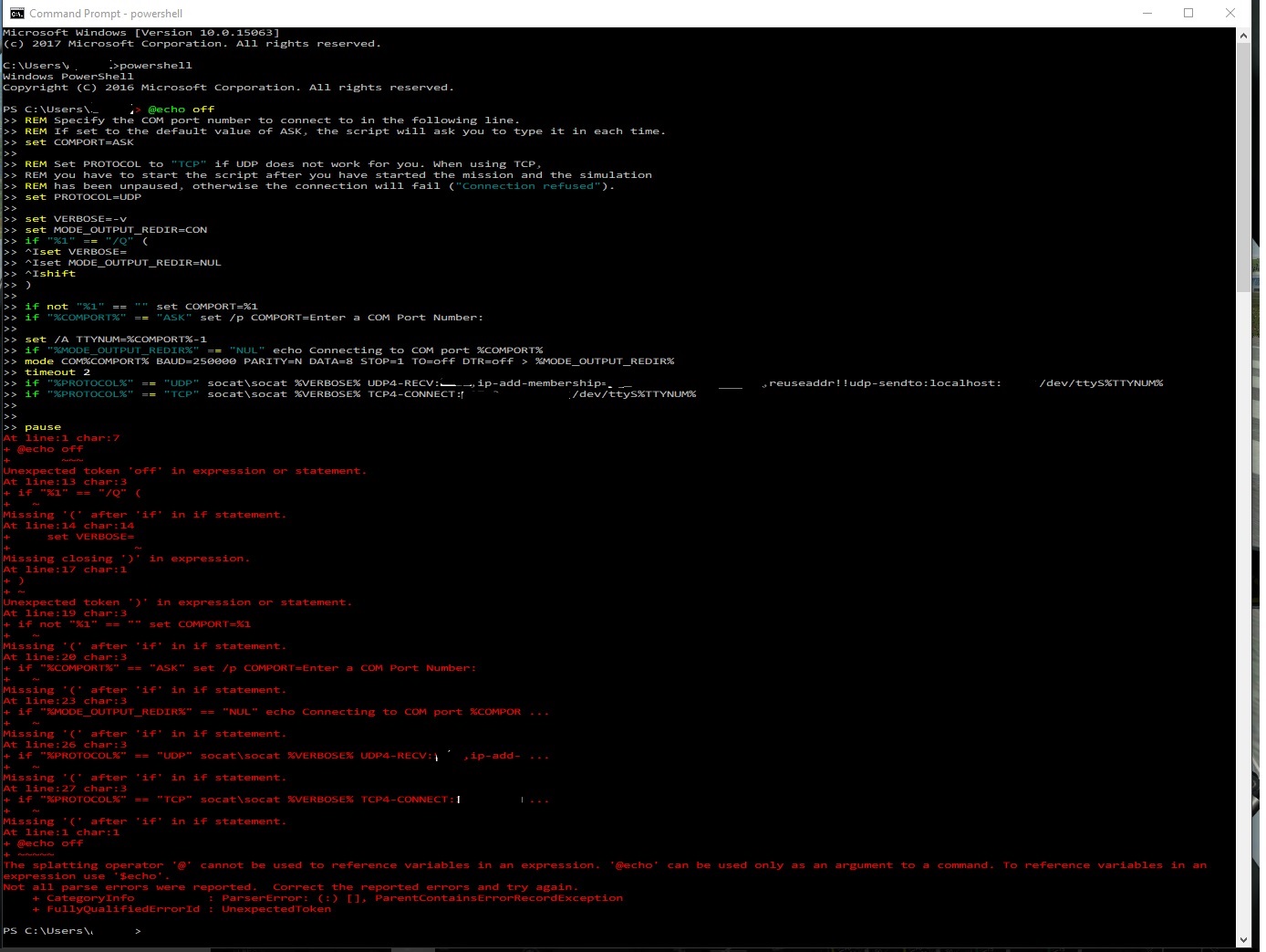
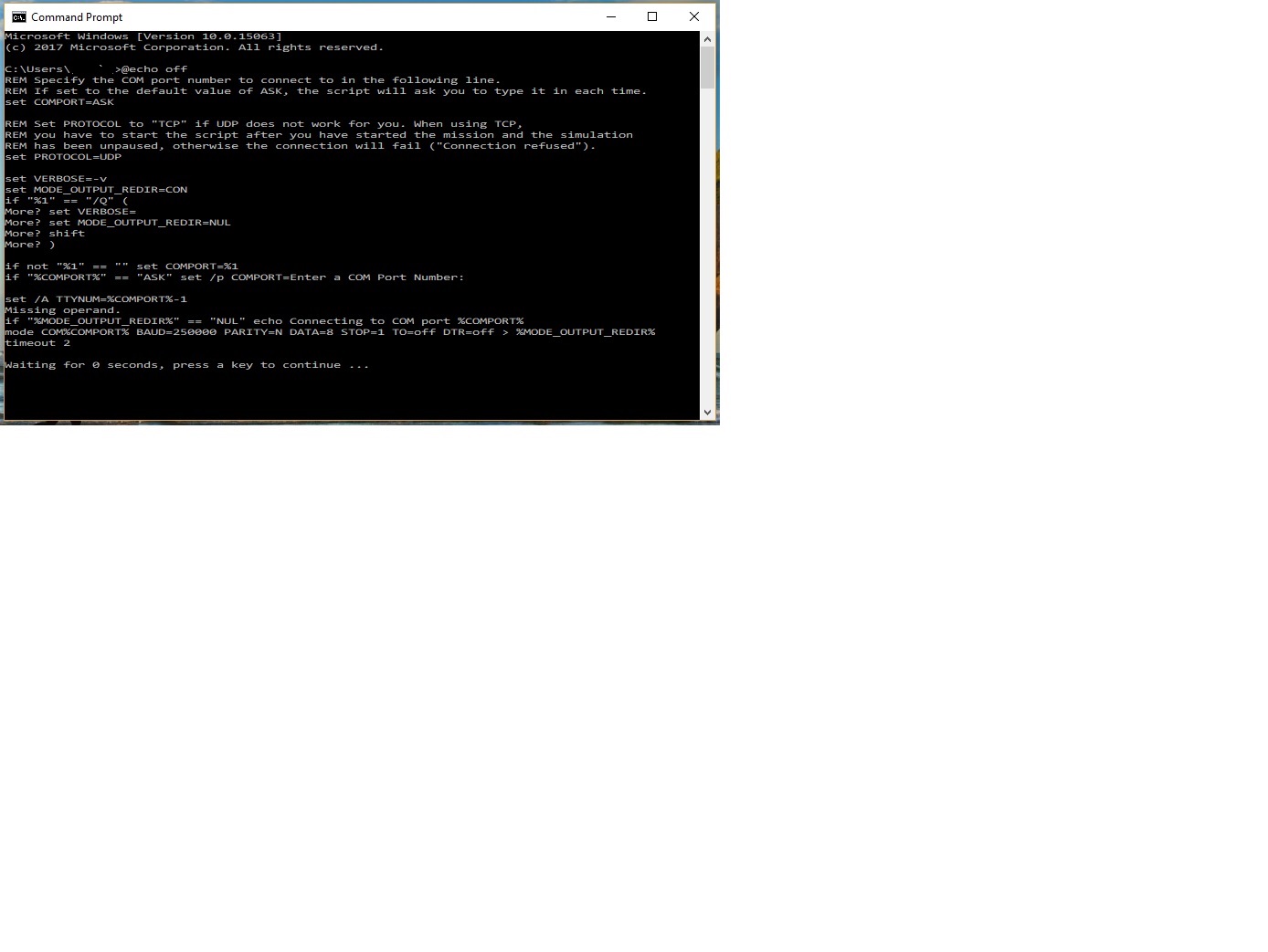
Thanks Ian. I have windows 10 as my operating system. I noticed in the forums some difference in syntax between windows 10 and other versions when trying to install that Normandy Map and WWII Asset pack using cmd prompt. So I tried both regular cmd prompt and then entered powershell and pasted the code. I attached the error message I got when in powershell. When executed from cmd prompt, it counted down to 0 and then infinite pause. I included the snap shot as pic 2.

-
I like the detailed engineering you did in regards to laying out the RS-485 (EIA-485) bus. Most people at work don't even bother to calculate anything. I'm on a project now where the engineer bought a RS485 driver (from company A) for the host to drive about a dozen devices (from company B) related to the visual projectors. They have no idea how many devices the driver can support. It could be 40 or it could be 5. They don't use 120 impedance matched wire, clueless in regards to termination resistors, clueless in regards to bias resistors, clueless weather to use 100 ohm resistor to stop ground loop currents, etc, etc. Anyways, yes I was managing by not moving the USB connections around to avoid windows reassigning the com ports. The main issue I had was that the Arduino Mega never worked with DCS BIOS for some reason. I tried the authentic one and the Chinese version and both drivers. Driver CH341 for the clone and arduino for the real one. It works if I use generic sketches like blink, or other stuff, but not with DCS BIOS sketches. I looked at the properties of the driver and maybe there is a settings there I need to tweak. Also have the Atmel-ICE Basic brand new in the box, but I'll open another thread to troubleshoot that one. At worse case for now, I may try and use the arduino Nano with the MAX487 chips, or maybe there is a quick fix for my Mega issue. It would have been awesome if there were a quick fix for socat being that I think I only needed about 3 more Nano(s) to complete the Left and Right Consoles. Maybe another 4 would finish the main instrument panel.
-
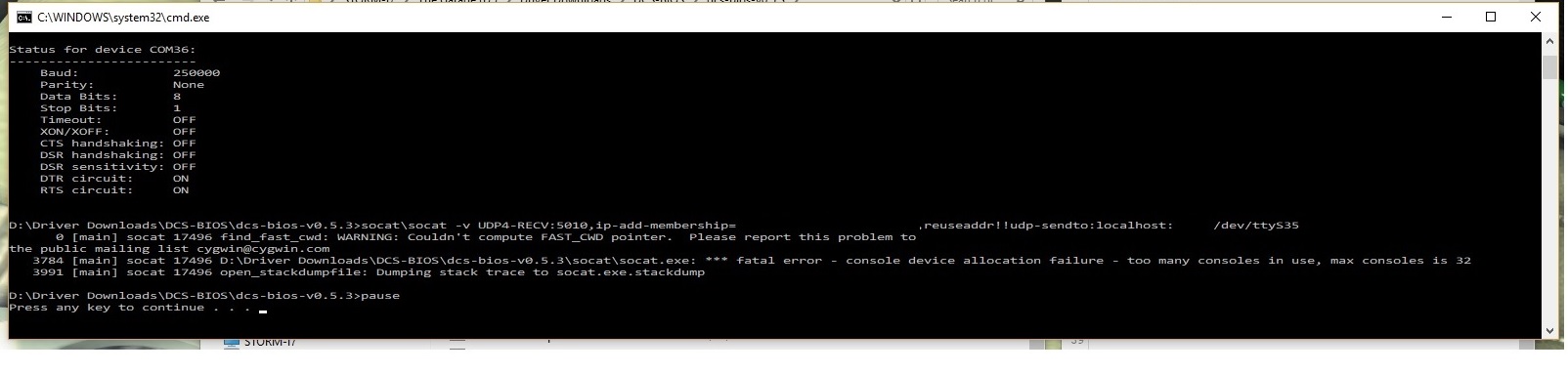
Ian, I was adding one more panel to my A-10C Cockpit and when I executed my 33rd socat file it gave me the following error message: *** fatal error - console device allocation failure - too many consoles in use, max console is 32 Is there a way around this limitation or a way to increase this to say 48? Thanks.
-
[DCS-BIOS v0.5.3] A-10C Lighting Control Panel Sample Code
GSS Rain replied to GSS Rain's topic in Home Cockpits
Thanks Ian. -
[DCS-BIOS v0.5.3] A-10C Lighting Control Panel Sample Code
GSS Rain replied to GSS Rain's topic in Home Cockpits
I'll take a look at that. I did have an anomaly where If the coil was commanded off do to say the pinky switch on the HOTAS, I could toggle the switch anti-collision switch up and down on the panel. The switch would not engage, which is normal, but the graphic in the game always showed the switch off (not moving). The graphic in the game should have showed the switch moving up and down as I was physically moving the switch. Even though it would not grab to the "ON" position, you still should see it moving. I think the way you have it illustrated will fix that. I saw the LED line but wasn't sure if that was tied to the switch location or coil state. Thanks Hans. -
Good Day, I used this sample code to drive the A-10C Lighting Control Panel. The version of DCS-BIOS at the time was v0.5.3. The only thing of note is the Ant-collision switch coil which is connected to pin 8 of the arduino which is setup as a Digital Output to drive the coil circuit. /* * DCS BIOS version 0.5.3 */ #define DCSBIOS_IRQ_SERIAL #include "DcsBios.h" int Anticollision_Coil = 8; // Position Lights FLASH/OFF/STEADY DcsBios::Switch3Pos lcpPosition("LCP_POSITION", 2, 3); // Formation Lights DcsBios::Potentiometer lcpFormation("LCP_FORMATION", A7); // Anticollision Lights (Magnetically Held Toggle Switch) DcsBios::Switch2Pos lcpAnticollision("LCP_ANTICOLLISION", 4); // Anticollision Lights Coil void onLcpAnticollisionChange(unsigned int newCoilValue) { switch (newCoilValue){ case 0: digitalWrite(Anticollision_Coil, LOW); break; case 1: digitalWrite(Anticollision_Coil, HIGH); break; } } DcsBios::IntegerBuffer lcpAnticollisionBuffer(0x1144, 0x0080, 7, onLcpAnticollisionChange); // Engine Instrument Lights DcsBios::Potentiometer lcpEngInst("LCP_ENG_INST", A6); // Nose Illumination DcsBios::Switch2Pos lcpNoseIllum("LCP_NOSE_ILLUM", 5); // Aux Instrument Lights DcsBios::Potentiometer lcpAuxInst("LCP_AUX_INST", A5); // Signal Lights DcsBios::Switch2Pos lcpSignalLights("LCP_SIGNAL_LIGHTS", 6); // Flight Instrument Lights DcsBios::Potentiometer lcpFlightInst("LCP_FLIGHT_INST", A4); // Accelerometer and Compass Lights DcsBios::Switch2Pos lcpAccelComp("LCP_ACCEL_COMP", 7); // Flood Lights DcsBios::Potentiometer lcpFlood("LCP_FLOOD", A3); // Console Lights DcsBios::Potentiometer lcpConsole("LCP_CONSOLE", A2); void setup() { DcsBios::setup(); pinMode (Anticollision_Coil, OUTPUT); } void loop() { DcsBios::loop(); }
-
Cant play. need module armor and technic
GSS Rain replied to FZG_Immel's topic in DCS: WWII Assets Pack
I read somewhere in the forums that .\dcs_updater.exe was for windows 10 users. -
Some have been asking for the code for Fuel Quantity Gauge for the A-10C. This one drives the 7 segment display using the MAX7219 chip. Also a few other items are driven with the same arduino other than the fuel gauge. /* Fuel Panel and Front Dash */ #define DCSBIOS_DEFAULT_SERIAL #include "DcsBios.h" #include <LedControl.h> #include <Servo.h> #include <Wire.h> Servo FuelQtyLeft_gauge; // create servo object to control a servo motor Servo FuelQtyRight_gauge; // create servo object to control a servo motor Servo L_HYD_Press_gauge; // create servo object to control a servo motor Servo R_HYD_Press_gauge; // create servo object to control a servo motor // MAX 7219 only works with Common Cathode Displays // inputs: DIN pin, CLK pin, LOAD (/CS) pin. number of MAX7219chips LedControl FuelDisplay = LedControl(12, 11, 10, 1); int val_1 = 0; int val_2 = 0; int val_3 = 0; void setup() { DcsBios::setup(); FuelDisplay.shutdown(0, false); // turns on display FuelDisplay.setIntensity(0, 10); // 15 = brightest FuelQtyLeft_gauge.attach(3); // attaches the servo on pin 3 to the servo object FuelQtyRight_gauge.attach(5); // attaches the servo on pin 5 to the servo object L_HYD_Press_gauge.attach(6); // attaches the servo on pin 6 to the servo object R_HYD_Press_gauge.attach(9); // attaches the servo on pin 9 to the servo object } void loop() { DcsBios::loop(); } // GUN READY Indicator DcsBios::LED gunReady(0x1026, 0x8000, 13); // Nosewheel Steering Indicator DcsBios::LED nosewheelSteering(0x10da, 0x0001, 2); // MARKER BEACON Indicator DcsBios::LED markerBeacon(0x10da, 0x0002, 4); // CANOPY UNLOCKED Indicator DcsBios::LED canopyUnlocked(0x10da, 0x0004, 7); // Fuel Display Selector const byte fqisSelectPins[5] = {A0, A1, A2, A3, A4}; DcsBios::SwitchMultiPos fqisSelect("FQIS_SELECT", fqisSelectPins, 5); // Fuel Gauge Test DcsBios::Switch2Pos fqisTest("FQIS_TEST", A5); // Fuel Quantity Counter 10000 void onFuelQty10000Change(unsigned int newValue1) { unsigned int value1 = (newValue1 & 0xffff) >> 0; unsigned int Disp_Digit_1 = map(value1, 0, 65535, 0, 10000); val_1 = Disp_Digit_1; if (Disp_Digit_1 > 501) {val_1 = 1;} else {val_1 = 0;} FuelDisplay.setDigit(0, 0, val_1, false); // Print "10,000"'s slot FuelDisplay.setDigit(0, 3, 0, false); // Blank out "10"s slot FuelDisplay.setDigit(0, 4, 0, false); // Blank out "1"s slot } DcsBios::IntegerBuffer fuelQty10000Buffer(0x10ce, 0xffff, 0, onFuelQty10000Change); // Fuel Quantity Counter 1000 void onFuelQty1000Change(unsigned int newValue2) { unsigned int value2 = (newValue2 & 0xffff) >> 0; unsigned int Disp_Digit_2 = map(value2, 0, 65535, 0, 1000); val_2 = Disp_Digit_2; if (val_2 > 900) {val_2 = 0;} else if (val_2 > 800) {val_2 = 9;} else if (val_2 > 700) {val_2 = 8;} else if (val_2 > 600) {val_2 = 7;} else if (val_2 > 500) {val_2 = 6;} else if (val_2 > 400) {val_2 = 5;} else if (val_2 > 300) {val_2 = 4;} else if (val_2 > 200) {val_2 = 3;} else if (val_2 > 100) {val_2 = 2;} else {val_2 = 1;} FuelDisplay.setDigit(0, 1, val_2, false); // Print "1,000"'s slot FuelDisplay.setDigit(0, 3, 0, false); // Blank out "10"s slot FuelDisplay.setDigit(0, 4, 0, false); // Blank out "1"s slot } DcsBios::IntegerBuffer fuelQty1000Buffer(0x10d0, 0xffff, 0, onFuelQty1000Change); // Fuel Quantity Counter 100 void onFuelQty100Change(unsigned int newValue3) { unsigned int value3 = (newValue3 & 0xffff) >> 0; unsigned int Disp_Digit_3 = map(value3, 0, 65535, 0, 100); val_3 = Disp_Digit_3; if (val_3 > 90) {val_3 = 0;} else if (val_3 > 80) {val_3 = 9;} else if (val_3 > 70) {val_3 = 8;} else if (val_3 > 60) {val_3 = 7;} else if (val_3 > 50) {val_3 = 6;} else if (val_3 > 40) {val_3 = 5;} else if (val_3 > 30) {val_3 = 4;} else if (val_3 > 20) {val_3 = 3;} else if (val_3 > 10) {val_3 = 2;} else {val_3 = 1;} FuelDisplay.setDigit(0, 2, val_3, false); // Print "100"'s slot FuelDisplay.setDigit(0, 3, 0, false); // Blank out "10"s slot FuelDisplay.setDigit(0, 4, 0, false); // Blank out "1"s slot } DcsBios::IntegerBuffer fuelQty100Buffer(0x10d2, 0xffff, 0, onFuelQty100Change); // Fuel Qty Left void onFuelQtyLChange(unsigned int newFuel_L_Value) { unsigned int FuelQtyLeft_Value = (newFuel_L_Value & 0xffff) >> 0; unsigned int FuelQtyLeft = map(FuelQtyLeft_Value, 0, 65535, 0, 110); FuelQtyLeft_gauge.write(FuelQtyLeft); } DcsBios::IntegerBuffer fuelQtyLBuffer(0x10ca, 0xffff, 0, onFuelQtyLChange); // Fuel Qty Right void onFuelQtyRChange(unsigned int newFuel_R_Value) { unsigned int FuelQtyRight_Value = (newFuel_R_Value & 0xffff) >> 0; unsigned int FuelQtyRight = map(FuelQtyRight_Value, 0, 65535, 110, 0); FuelQtyRight_gauge.write(FuelQtyRight); } DcsBios::IntegerBuffer fuelQtyRBuffer(0x10cc, 0xffff, 0, onFuelQtyRChange); // Left Hydraulic Pressure void onLHydPressChange(unsigned int newL_HYD_Press_Value) { unsigned int L_HYD_Press_Value = (newL_HYD_Press_Value & 0xffff) >> 0; unsigned int L_HYD_Press = map(L_HYD_Press_Value, 0, 65535, 0, 180); L_HYD_Press_gauge.write(L_HYD_Press); } DcsBios::IntegerBuffer lHydPressBuffer(0x10c2, 0xffff, 0, onLHydPressChange); // Right Hydraulic Pressure void onRHydPressChange(unsigned int newR_HYD_Press_Value) { unsigned int R_HYD_Press_Value = (newR_HYD_Press_Value & 0xffff) >> 0; unsigned int R_HYD_Press = map(R_HYD_Press_Value, 0, 65535, 0, 180); R_HYD_Press_gauge.write(R_HYD_Press); } DcsBios::IntegerBuffer rHydPressBuffer(0x10c4, 0xffff, 0, onRHydPressChange);
-
Some have been asking about the script for the CMSC panel for the A-10C. Counter Measure Set Control Panel Arduino Nano or Uno is driving 74HC595N which in turn is driving the HDSP-2531. This script drives 2 of the 3 displays that are on the CMSC. The third display is driven by a separate Arduino/HDSP-2531 combo. /* CMSC Chaff/Flare Display and MWS Display * Trouble-shooting notes, if power wire comes loose from TB then it not work right. * * Two HDSP-2531 being wired to two 74HC595N * HDSP-2531 pin 2 "/Flash Ram" - 5VDC * HDSP-2531 pin 10 "A4" - No Connect * HDSP-2531 pin 11 "Clock Source" - 5VDC * HDSP-2531 pin 12 "Clock In/Out" - No Connect * HDSP-2531 pin 17 "Thermal Test" - No Connect * HDSP-2531 pin 15 "Vcc" - 5VDC * HDSP-2531 pin 16 "GND" - Ground * HDSP-2531 pin 18 "GND" - Ground * HDSP-2531 pin 19 "Read" - No Connect */ #define DCSBIOS_IRQ_SERIAL #include "DcsBios.h" // HDSP-2531 Chip #1 int RST = A0; // HDSP-2531 pin 1 (share amoungst the two chips) int WR = A1; // HDSP-2531 pin 13 int CE = 10; // HDSP-2531 pin 14 int AD0 = A2; // HDSP-2531 pin 3 int AD1 = A3; // HDSP-2531 pin 4 int AD2 = A4; // HDSP-2531 pin 5 int AD3 = A5; // HDSP-2531 pin 6 (share amoungst the two chips) int DS = 2; // 74HC595N pin 14 shift register data pin int ST_CP = 3; // 74HC595N pin 12 shift register storage clock(latch) int SH_CP = 4; // 74HC595N pin 11 shift register shift clock(data polling) // HDSP-2531 Chip #2 int WR_2 = 5; // HDSP-2531 pin 13 int CE_2 = 6; // HDSP-2531 pin 14 int AD0_2 = 7; // HDSP-2531 pin 3 int AD1_2 = 8; // HDSP-2531 pin 4 int AD2_2 = 9; // HDSP-2531 pin 5 int DS_2 = 11; // 74HC595N pin 14 shift register data pin int ST_CP_2 = 12; // 74HC595N pin 12 shift register storage clock(latch) int SH_CP_2 = 13; // 74HC595N pin 11 shift register shift clock(data polling) /* * HDSP-2531 to 74HC595N wiring * HDSP-2531 "D0" pin 20 to 74HC595N pin 15 * HDSP-2531 "D1" pin 21 to 74HC595N pin 1 * HDSP-2531 "D2" pin 25 to 74HC595N pin 2 * HDSP-2531 "D3" pin 26 to 74HC595N pin 3 * HDSP-2531 "D4" pin 27 to 74HC595N pin 4 * HDSP-2531 "D5" pin 28 to 74HC595N pin 5 * HDSP-2531 "D6" pin 29 to 74HC595N pin 6 * HDSP-2531 "D7" pin 30 to 74HC595N pin 7 * 74HC595N "/MasterReset" pin 10 to 5V * 74HC595N "/OutputEnable" pin 13 to GND * 74HC595N "Data Out" pin 9 to No Connect * 74HC595N "Ground" pin 8 to GND * 74HC595N "Vcc" pin 16 to 5V */ void setup() { DcsBios::setup(); pinMode(RST, OUTPUT); pinMode(WR, OUTPUT); pinMode(WR_2, OUTPUT); pinMode(CE, OUTPUT); pinMode(CE_2, OUTPUT); pinMode(AD0, OUTPUT); // data register selection // these 4 pins allow one to select a data register. pinMode(AD0_2, OUTPUT); pinMode(AD1, OUTPUT); // data register selection pinMode(AD1_2, OUTPUT); pinMode(AD2, OUTPUT); // data register selection pinMode(AD2_2, OUTPUT); pinMode(AD3, OUTPUT); // data register selection pinMode(DS, OUTPUT); // shift register serial in pinMode(DS_2, OUTPUT); pinMode(ST_CP, OUTPUT); // shift register storage pin(latch) pinMode(ST_CP_2, OUTPUT); pinMode(SH_CP, OUTPUT); // shift register clock pin(clock) pinMode(SH_CP_2, OUTPUT); digitalWrite(CE, HIGH); // chip enable, go low before write. go high after write digitalWrite(CE_2, HIGH); digitalWrite(WR, HIGH); // write enable, go low to start write, go high when done. digitalWrite(WR_2, HIGH); resetDisplay(); } void resetDisplay() { digitalWrite(RST, LOW); delayMicroseconds(1); digitalWrite(RST,HIGH); delayMicroseconds(150); digitalWrite(AD3, HIGH); } void writeChaffDisplay(char *input) { for (int i=0; i<8; i++) { digitalWrite(AD0, (1&i)!=0?HIGH:LOW); // character address because there are 8 alphanumeric digits digitalWrite(AD1, (2&i)!=0?HIGH:LOW); // 000 is digit on far left. 111 is digit on far right digitalWrite(AD2, (4&i)!=0?HIGH:LOW); delay(1); digitalWrite(CE, LOW); delay(1); digitalWrite(WR, LOW); delay(1); digitalWrite(ST_CP, LOW); delay(1); //allow the display to retrieve the values set to the Data pins shiftOut(DS, SH_CP, MSBFIRST, input); delay(1); digitalWrite(ST_CP, HIGH); delay(1); digitalWrite(WR, HIGH); delay(1); digitalWrite(CE, HIGH); delay(1); } } void writeMWSDisplay(char *input) { for (int i=0; i<8; i++) { digitalWrite(AD0_2, (1&i)!=0?HIGH:LOW); // character address because there are 8 alphanumeric digits digitalWrite(AD1_2, (2&i)!=0?HIGH:LOW); // 000 is digit on far left. 111 is digit on far right digitalWrite(AD2_2, (4&i)!=0?HIGH:LOW); delay(1); digitalWrite(CE_2, LOW); delay(1); digitalWrite(WR_2, LOW); delay(1); digitalWrite(ST_CP_2, LOW); delay(1); //allow the display to retrieve the values set to the Data pins shiftOut(DS_2, SH_CP_2, MSBFIRST, input); delay(1); digitalWrite(ST_CP_2, HIGH); delay(1); digitalWrite(WR_2, HIGH); delay(1); digitalWrite(CE_2, HIGH); delay(1); } } void loop() { DcsBios::loop(); } // Chaff / Flare Amount Display void onCmscTxtChaffFlareChange(char* newValue) { writeChaffDisplay(newValue); } DcsBios::StringBuffer<8> cmscTxtChaffFlareBuffer(0x108e, onCmscTxtChaffFlareChange); // MWS Status Display void onCmscTxtMwsChange(char* newValue) { writeMWSDisplay(newValue); } DcsBios::StringBuffer<8> cmscTxtMwsBuffer(0x12b0, onCmscTxtMwsChange);
-
Wwwwwaaaahhhh, his power level is over 9,000 ! ! ! Sweet build. Good job.
-
Wow. That is impressive. You really know your system.
-
I had some spare time and wanted to record some bench mark settings using DCS-Bios. One such bench mark was measuring the response time for sending data to the sim and then getting a response back. I measured less than 125 milliseconds which is good considering all the USB ports I'm using to run the simulation. I was curious as to how much faster would using RS-485 be. I posted a link to YouTube.
-
[FSF]Ian, that code worked like a charm. If anyone is using a similar display, I listed the complete code for reference. /* TACAN Panel Adafruit Alphanumeric Display with backpack. Wiring for the Display using 5 pin backpack. A5 to Clock pin A4 to Data pin 5V to + 5V to + (There are two pins labeled +) Gnd to - Rotary Encoders need four 10k resistors each and two 0.01uf capacitors Bourns PEC11R Series */ #define DCSBIOS_DEFAULT_SERIAL #include "DcsBios.h" #include <Wire.h> // this library is needed to drive i2C #include "Adafruit_LEDBackpack.h" // vendor custom library #include "Adafruit_GFX.h" // vendor custom library Adafruit_AlphaNum4 alpha4 = Adafruit_AlphaNum4(); // Left Channel Selector DcsBios::RotaryEncoder tacan10("TACAN_10", "DEC", "INC", 4, 2); // Right Channel Selector DcsBios::RotaryEncoder tacan1("TACAN_1", "DEC", "INC", 5, 3); // TACAN Channel X/Y Toggle DcsBios::ActionButton tacanXyToggle("TACAN_XY", "TOGGLE", 6); // TACAN Mode Dial const byte tacanModePins[5] = {7, 8, 9, 10, 11}; DcsBios::SwitchMultiPos tacanMode("TACAN_MODE", tacanModePins, 5); // we need to monitor both the TACAN channel: DcsBios::StringBuffer<4> tacanChannelBuffer(0x1162, NULL); // and the mode switch: DcsBios::IntegerBuffer tacanModeBuffer(0x1168, 0x000e, 1, NULL); // TACAN Test Indicator Light DcsBios::LED tacanTest(0x10da, 0x0400, 13); // TACAN Test Button DcsBios::Switch2Pos tacanTestBtn("TACAN_TEST_BTN", 12); // TACAN Signal Volume // DcsBios::Potentiometer tacanVol("TACAN_VOL", A7); void setup() { DcsBios::setup(); alpha4.begin(0x70); // pass in the address } void loop() { DcsBios::loop(); if (tacanChannelBuffer.hasUpdatedData() || tacanModeBuffer.hasUpdatedData()) { // if either of those values has been updated, update the display if (tacanModeBuffer.getData() == 0) { // mode dial in OFF position alpha4.writeDigitAscii(0, ' '); // Blank Display if Mode knob is set to Off. alpha4.writeDigitAscii(1, ' '); // 0 is left most display, 3 is right most display alpha4.writeDigitAscii(2, ' '); alpha4.writeDigitAscii(3, ' '); } else { char* channelStr = tacanChannelBuffer.getData(); alpha4.writeDigitAscii(0, channelStr[0]); alpha4.writeDigitAscii(1, channelStr[1]); alpha4.writeDigitAscii(2, channelStr[2]); alpha4.writeDigitAscii(3, channelStr[3]); } } alpha4.writeDisplay(); // Outputs one or the other of the above code to the Display }
-
Thanks BravoYankee4, that's good to know. I've also been looking for a supplier for the VID60-02 Stepper Motor. I tried twice from vendors on Aliexpress. Both companies where in China and on both occasions I never received the motors. I've been trying to get that one because I think it has a built in switch that reports when it hits the 12'oclock position.
-
Hi Kada, I don't think you will find a 360° servo. They are usually up to 180° max. I used my 3D printer to print out a 1 to 2 gear ratio to achieve the necessary swing on the needle pointer. I used a small 18 tooth gear on the pointer and a 36 tooth gear on the servo. Unfortunately, your options are limited without the gears. Tower Pro Micro Servo 9g is a popular motor. I called the manufacturer and also Servocity and no one makes a gear set that fits the output shaft. So I went to a few popular 3D CAD sites such as Thingiverse or GrabCAD, etc... and download a gear set and then scaled it to fit. This site has some servo gears so you can get an idea. However, the smallest gear that they sell fits the motor that's one size larger than the TowerPro Micro 9G. https://www.servocity.com/motion-components/rotary-motion/gears/servo-mount-gears
-
[FSF]Ian, I tried the code and it highlighted the following line and gave me an error message in the view window. I googled the error and it seams to be related to the following term : How to implement Inheritance in C++ and resolve the error “parent class is not accessible base of child class”? if (tacanChannelBuffer.hasUpdatedData() || tacanModeBuffer.hasUpdatedData()) { Arduino: 1.6.12 (Windows 10), Board: "Arduino Nano, ATmega328" In file included from C:\Users\Joseph\Documents\Arduino\libraries\dcs-bios-arduino-library-0.2.5/DcsBios.h:10:0, from C:\Users\Joseph\Documents\Arduino\Digital Combat Simulator\Version 0.5.0\TACAN_Panel\TACAN_Panel.ino:15: C:\Users\Joseph\Documents\Arduino\libraries\dcs-bios-arduino-library-0.2.5/ExportStreamListener.h: In function 'void loop()': C:\Users\Joseph\Documents\Arduino\libraries\dcs-bios-arduino-library-0.2.5/ExportStreamListener.h:79:9: error: 'bool DcsBios::Int16Buffer::hasUpdatedData()' is inaccessible bool hasUpdatedData() { return (this->flags & DIRTY); } ^ TACAN_Panel:80: error: within this context if (tacanChannelBuffer.hasUpdatedData() || tacanModeBuffer.hasUpdatedData()) { ^ TACAN_Panel:80: error: 'DcsBios::Int16Buffer' is not an accessible base of 'DcsBios::IntegerBuffer' exit status 1 within this context This report would have more information with "Show verbose output during compilation" option enabled in File -> Preferences.
-
I read that AccelStepper.h was a good one to use. I used this one time as a test run for the engine panel gauges. It includes several example sketches in its library. It can be downloaded here : http://www.airspayce.com/mikem/arduino/AccelStepper/ But I went with servo motors instead for the engine gauges because they use just one I/O point from the arduino card vs 4 from some stepper motors. I believe you just need the following references to make it work with DCS Bios. #define DCSBIOS_IRQ_SERIAL #include "DcsBios.h" #include <Wire.h> #include <AccelStepper.h>
-
Thank you Professor [FSF]Ian. I'll study this code to improve my programming skills. This gets me pointed in the right direction. I need to study : .hasUpdateData() .getData()
-
I need the help of someone who knows how to write code. For my TACAN I'm using an adafruit alphanumeric display. When the Mode dial is turned to OFF position, I'm trying to blank the display so that it appears off. So I need to call the onTacanChannelChange routine not only when the Tacan frequency changes, but also when the Mode dial changes from the off position. The problem is I store the latest string from onTacanChannelChange to the variable name TACAN, however when I try to update the display by calling the onTacanChannelChange routine from the onTacanModeChange routine, it will NOT let me pass the variable name TACAN to onTacanChannelChange. The error message is choking on the char* expression from the code void onTacanChannelChange(char* newValue) {}. So what code should I write to pass a stored string to that routine? I listed my code below. The work around I used is that I hard coded a character value to pass to the routine but it has a side effect of displaying garbage when I first move from the off position and it stays displaying garbage unitl I rotate the freq knob to get the display to update. #define DCSBIOS_DEFAULT_SERIAL #include "DcsBios.h" #include <Wire.h> // this library is needed to drive i2C #include "Adafruit_LEDBackpack.h" // vendor custom library #include "Adafruit_GFX.h" // vendor custom library Adafruit_AlphaNum4 alpha4 = Adafruit_AlphaNum4(); String TACAN = ""; // Declare global new string variable char Digit0 = ""; // Declare global new character variable char Digit1 = ""; char Digit2 = ""; char Digit3 = ""; int TACAN_power = 0; // TACAN Mode Dial const byte tacanModePins[5] = {7, 8, 9, 10, 11}; DcsBios::SwitchMultiPos tacanMode("TACAN_MODE", tacanModePins, 5); void onTacanModeChange(unsigned int newModeValue) { TACAN_power = newModeValue; // If Mode knob is set to Off, this value will be 0. if (TACAN_power == 0 || TACAN_power == 1) // Is mode knob off, or next position over { onTacanChannelChange (TACAN); // Call routine to write blanks to the display if power goes from off to on, or on to off. Otherwise, no need to refresh display } } DcsBios::IntegerBuffer tacanModeBuffer(0x1168, 0x000e, 1, onTacanModeChange); // TACAN Channel void onTacanChannelChange(char* newValue) { TACAN = newValue; // Store incoming char string to a new string variable name Digit0 = TACAN.charAt(0); // grab individual char value at that specific index in the string Digit1 = TACAN.charAt(1); Digit2 = TACAN.charAt(2); Digit3 = TACAN.charAt(3); if (TACAN_power == 0) { alpha4.writeDigitAscii(0, ' '); // Blank Display if Mode knob is set to Off. alpha4.writeDigitAscii(1, ' '); // 0 is left most display, 3 is right most display alpha4.writeDigitAscii(2, ' '); alpha4.writeDigitAscii(3, ' '); } else { alpha4.writeDigitAscii(0, Digit0); // Send only that character at that specific location to the specific digit alpha4.writeDigitAscii(1, Digit1); // 0 is left most display, 3 is right most display alpha4.writeDigitAscii(2, Digit2); alpha4.writeDigitAscii(3, Digit3); } alpha4.writeDisplay(); // Write command to display characters stored in the chip buffer } DcsBios::StringBuffer<4> tacanChannelBuffer(0x1162, onTacanChannelChange);
-
Goodnight, in your code I see the following #define DCSBIOS_IRQ_SERIAL #define BACKLIGHT_PIN 3 #include <LiquidCrystal_I2C.h> #include <Wire.h> #include <Servo.h> #include <DcsBios.h> LiquidCrystal_I2C lcd1(0x21, 3, POSITIVE); LiquidCrystal_I2C lcd2(0x27, 3, POSITIVE); I think #include <DcsBios.h> should be #include "DcsBios.h" Also not sure why #include <Servo.h> is there. If you look at the template from dcs-bios-arduino-library-0.2.5 , you can see the latest format there. I maybe wrong though. I'm not a software programmer but sometimes I can use the rules from sesame street where you compare this vs that to see what doesn't match.
-
I just saw this promising addition to the game play of DCS and would like to try this out but I'm not sure about the install process. I have two computers at home that are on my local network. I read in the post that " DO NOT run the installer or install the Script on your Standalone server if its on the same network (but a separate PC) to your DCS PC." Can someone please walk me through how the install procedure would go in my situation. I already downloaded the file DCS-SimpleRadioStandalone-NewAudio-Release but have not unzipped it. Again for now I wanted to test this between my two local computers. Thanks.
-
Good day. I'm using DCS Bios v0.5.0 with arduino-library-0.2.1(master). I'm interested in setting the debounce delay time for switches. For example on my home made CMSP panel, if I rotate the mode knob between the difference positions, it reads it as an off state moving between say position 3 and 4. This happens even though the off state is tied to the PIN_0 position. I think if I put a delay of say 25ms I could pass from position 2 to 3 without triggering the off position. I saw once piece of code by Gadroc on github dealing with action buttons, but I don't think it will work with the latest version of DCS Bios. Has anyone been using debounce code in their sketches that you can share? Thanks. const byte cmspModePins[5] = {PIN_0, PIN_1, PIN_2, PIN_3, PIN_4}; DcsBios::SwitchMultiPos cmspMode("CMSP_MODE", cmspModePins, 5);
-
Good day all. Regarding my previous post, I remembered that I had the Saitek PZ55 flight switch panel plugged into my computer which also uses DCS-Bios to operate. Even though I wasn't running the ProUsbPanel application, the fact that I had it plugged into the computer was causing problems. So I unplugged all my usb devices except for the mouse, keyboard, webcam, and arduino Mega2560. The problem I am having now is that I get an error message when I compile the MasterCaution sketch from the dcs-bios-arduino-library-0.1.4. Please see attached pic for error message. So I commented out the push button and only tried to use the built in LED on pin 13 for master caution. And that part as well is not working for me. The LED just turns on and stays on as soon as the socat file is executed. The A-10C cockpit is powered off on the ramp so the LED should have remained off. If I run default Blink sketch from Arduino, that part works so I know the board is communicating. Any suggestions?? Thanks.
-
Thanks for the help Ian. Still no luck yet. I double checked and I was using an extracted uncompressed file (I think WinZip uncompressed it). So I downloaded fresh copy of DCS-BIOS 0.4.2 from Github straight to my desktop. I then downloaded 7-zip version 15.14 and extracted DCS-BIOS straight to desktop. I then ran Arduino , and then ran DCS World and selected A-10C. Once A-10C cockpit was running I then double left clicked connect-serial-port but I still get the same error message. Not sure if there are any debugging tools I could use.