Kenpilot
-
Posts
274 -
Joined
-
Last visited
Content Type
Profiles
Forums
Events
Everything posted by Kenpilot
-
Thanks Crash Test Pilot. I read through all of that but I'm not sure what I was supposed to take from it. I don't know how to code, I only know how to copy and paste the coding from dcs bios and put the pin numbers in. These are the encoders I'm using: Taiss / 5Pcs KY-040 Rotary Encoder Module with 15×16.5 mm with Knobs Cap https://a.co/d/7Yo186v
-
My rotary encoder was working fine and all of a sudden my rotary encoder stopped reacting normally. When I turn the knob left or right, doesn't matter how much I turn it, the yaw trim in the game just bounces back and forth a small distance. I replaced the encoder and checked the wiring and nothing helped. Any ideas? I tried re-uploading the arduino sketch and that didn't help either.
-
I'm using a rotary encoder for my course knob, connected to an arduino mega and using DCS bios. When I turn the knob one "detent", it makes it turn the course about 5-10 degrees, instead of just 1 degree. I added a capacitor to the wiring but it didn't help at all. Any ideas on how to fix this? Maybe something needs to be added or adjusted in the arduino sketch or dcs bios sketch? Thanks!
-
Awesome, thanks Vinc! I'm in the middle of a painting project , so it might be a day or two before I can try it out. I'll report back. Thanks again!
-
Copy that, thanks No1sonuk, I'll do that.
-
Thanks Vinc. I googled the display to find the data sheet like you did, and I found it, but it didn't really make sense to me so I used a multimeter to determine the pinout. Now that I did that, the data sheet makes sense. I'm learning, slowly but surely. I will wire the display using the example you provided and test it and let you know how it goes. I probably won't get to it until tomorrow though. As always, thank you!!
-
Update: I've figured out the pinout for the display: 1 - G 6 - D 2 - DP 7 - E 3 - A 8 - C 4 - F 9 - B 5 - CC (2nd Digit) 10 - CC (1st Digit) Now I just need to know how to wire them to the arduino and the sketch.
-
I received the displays today. These are the ones I got: https://www.amazon.com/dp/B07GTQ8NDC?psc=1&ref=ppx_yo2ov_dt_b_product_details. I don't mind just wiring the displays directly to the arduino, it's only 10 inputs. I just don't know how to wire them. I've looked at the link you sent, and also several others. I understand the pinout and how to wire a single 7 digit display to the arduino, but I don't understand how to wire a 2 digit 7 segment display. My displays have 5 pins on the bottom and 5 pins at the top. How do I wire the pins to the arduino? And then what would the sketch be for the display for the PRESET on the A10 VHF panel? Thank you!
-
Whichever is going to make it easier. The 7 segment displays I've used so far are the ones you helped me with, with the ILS and VHF frequency displays and they were 8 digits and had the driver chips already built with them. These don't. I wasn't sure if you could by them separately or not. So I don't mind buying some if that will make it easier. But I also don't know what to get.
-
Thanks Vinc, I went ahead and ordered the common cathode type LEDs. They should be here Friday. I ended up ordering the two digit 7 segment displays for the VHF Preset instead of the single displays and using two of them.
-
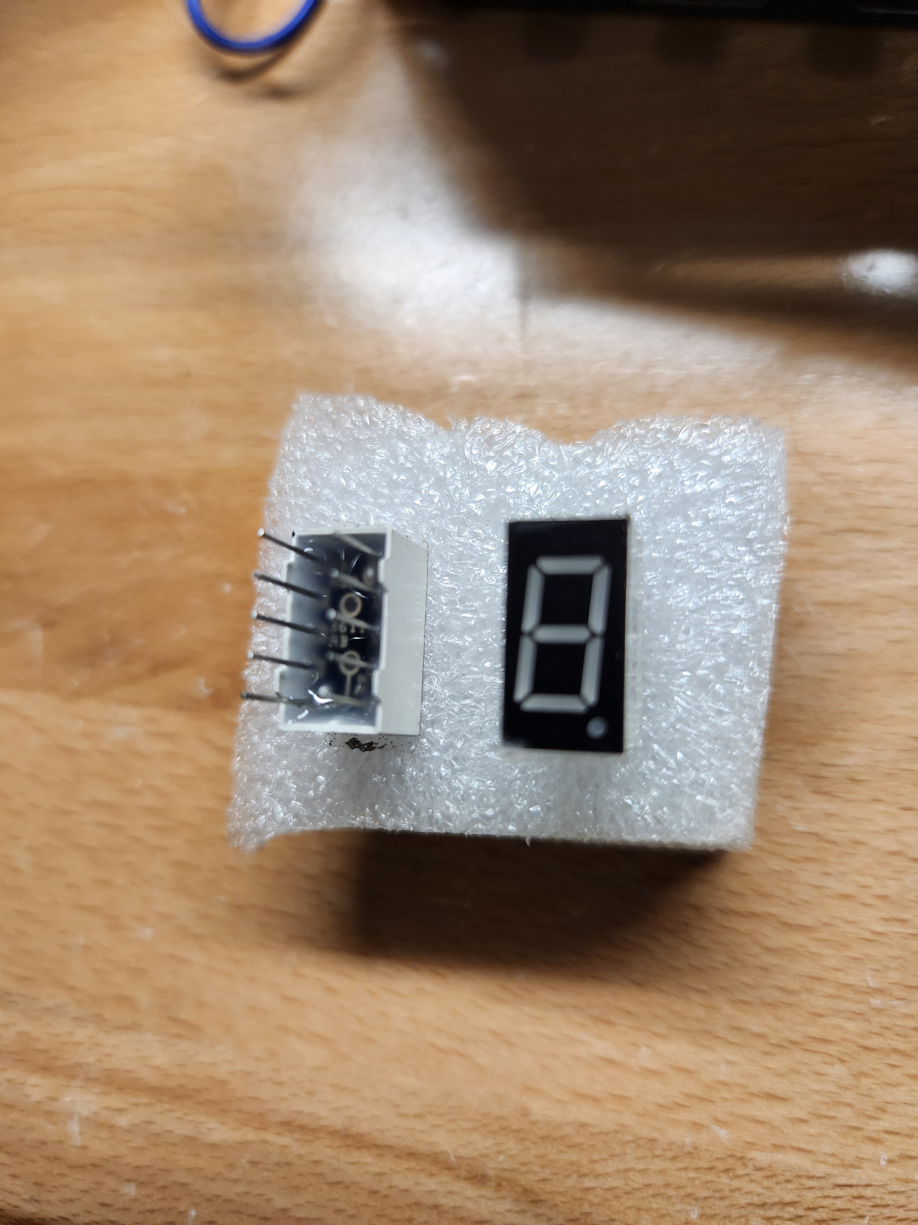
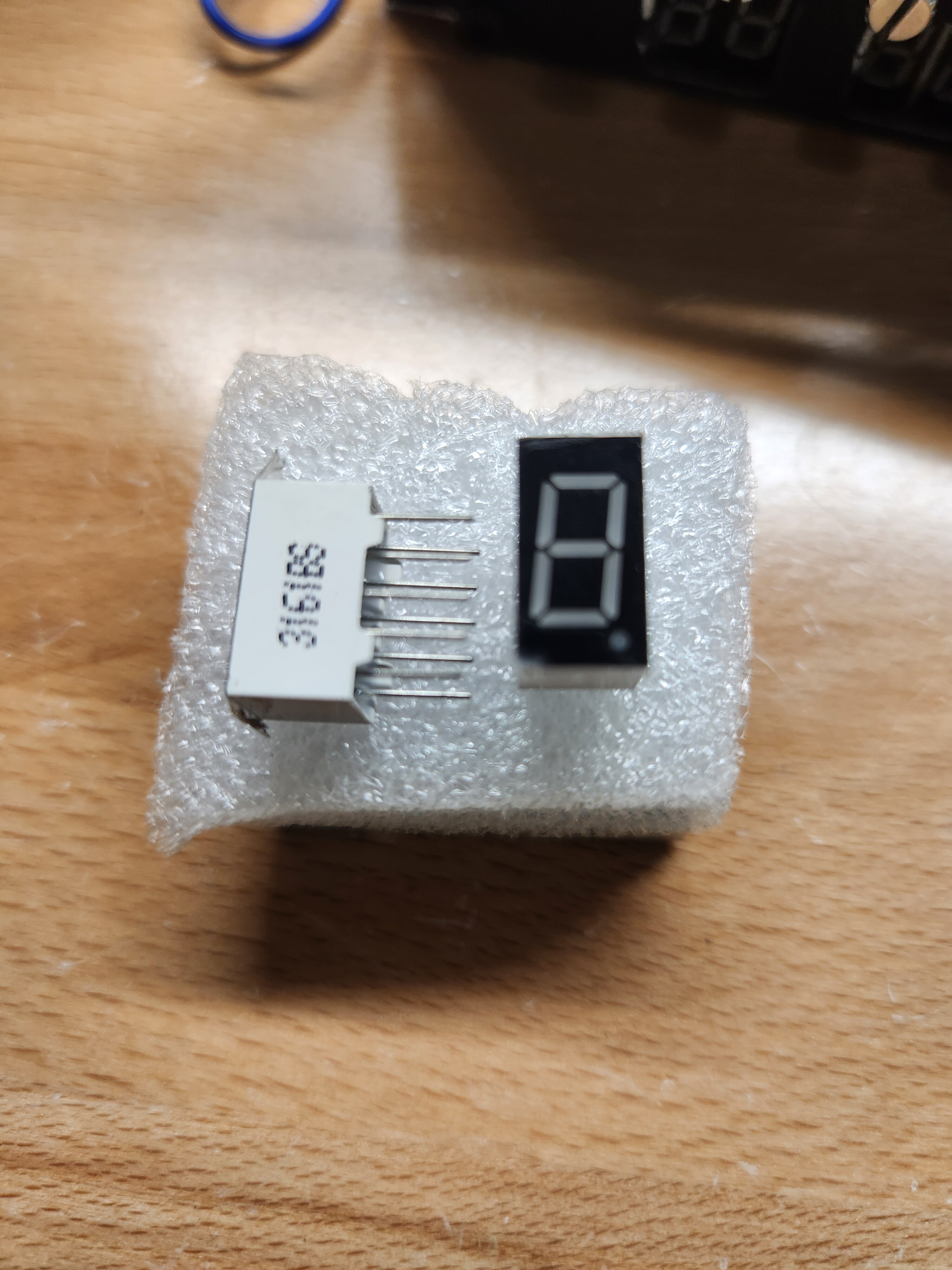
Hoping someone can help me with wiring two 7 segment displays and an arduino, and dcs bios sketch, for A10 VHF Pre-Select Channel Display. See attached pictures. uxcell Common Anode 10 Pin 1 Bit 7 Segment Display 0.55 x 0.3 x 0.33 Inch 0.35" Red LED Display Digital Tube 10pcs https://a.co/d/1yJ3wd0

-
The capacitors worked and it's working perfectly. now. Thanks No1sonuk!!
-
It's working!!!!! I think the reinstall did it! You guys rock!! Thank you SO much for your time and expertise!!!!
-
Thanks guys. I'm going to do the reinstall like Vinc suggested and see if that does it. I really can't see why else it wouldn't work. I figured it should still work even in a cold and dark cockpit, like No1sonuk said, but just trying to make sure I'm not missing anything. Hopefully the reinstall of DCS Bios will do it.
-
I tested another ON-OFF-(ON) switch with the same exact sketch as Vinc, but only using the DISP switch, and nothing else plugged in to the arduino, only this switch, and its still not working. I did test the switch on another panel and it is working. I'm stumped. I have absolutely no idea why none of these 4 switches are working. Is there another switch maybe that is on another panel that needs to be on or in a certain position for these toggle switches to be functional? Does the CMSP MODE switch need to be in a certain position? I'm out of ideas as to why in the world none of these 4 switches will work. I have seen several videos of other people's CMSP panel working with these switches, I'm just totally confused as to why mine won't work. This was the sketch: #define DCSBIOS_IRQ_SERIAL #include "DcsBios.h" /* paste code snippets from the reference documentation here */ DcsBios::Switch3Pos cmspDisp("CMSP_DISP", 2, 3); void setup() { DcsBios::setup(); } void loop() { DcsBios::loop(); }
-
Okay, will do, thanks guys. It won't be until probably tomorrow but I'll post it. Thanks!
-
I don't understand why these 4 switches will not work. I've tried the OFF-ON-(ON), OFF-ON-ON, ON-OFF-(ON), and a simple OFF-ON switch and none of them will work. Again, I have my simpit about 90% done, which as you all know, has A LOT of switches, and they all work, all kinds of different switches, so I know how to wire switches, copy the code from DCS Bios, and these are the only 4 switches that I can't get to work. Not just one, but all 4. Everything else on my CMSP panel is working fine. These are the DCS Bios commands that I'm using in my arduino sketch. I've tried different arduino boards, different inputs and nothing is working for these 4 switches, I just don't get it. Is there maybe an updated DCS Bios Command for these switches? I feel like that's the only problem that it could be at this point, is the DCS Bios command, its not working for some reason. Its not the switches or the wiring or the Arduino board, but the language in the sketch for some reason. Any thoughts? DcsBios::Switch3Pos cmspMws("CMSP_MWS", PIN_A, PIN_B); DcsBios::Switch3Pos cmspJmr("CMSP_JMR", PIN_A, PIN_B); DcsBios::Switch3Pos cmspRwr("CMSP_RWR", PIN_A, PIN_B); DcsBios::Switch3Pos cmspDisp("CMSP_DISP", PIN_A, PIN_B);
-
Awesome, thanks Deadman!
-
Okay awesome, thanks Vinc, I'll wire it up tonight and test it out!
-
Hey Vinc. The CMSP switches are OFF-ON-MENU. If I use ON-OFF-(ON) switches, how do I get them to act like OFF-ON-(ON) just like the ones in the sim? My ON-OFF-(ON) switches only have 3 terminals, middle being Ground. Or do I just wire them like normal and deal with the switch not being completely accurate with the real switches on the panel and just use them as ON-OFF -(MENU)? Thanks!
-
Those are actually the Rotary Encoders that I'm currently using, the KY-040 style. I do have the ones like the ones in No1sonuk's post. Should I use those instead with the capacitors? I guess it can't hurt to try them with the capacitors.
-
I'm trying to get the MWS, JMR, RWR, DISP switches on the CMSP wired and programmed and I'm not having any luck yet. I'm connecting the switches to an Arduino Mega and using DCS Bios. I've tried using OFF-ON-(ON) switches and then OFF-ON-ON switches and none of them have worked so far. I'm about 90% done with my sim pit and haven't had any other issues with wiring and programming switches so I'm not sure what's going on. I'm guessing since there are DCS Bios Sketches for these switches that they are able to be built and used in a home cockpit, or are they not and I've been wasting my time? Any help or suggestions would be greatly appreciated as far as what kind of switches you're using that are working or suggestions as to what I might be doing wrong with these. Thanks! .
-
I don't have capacitors attached, no, but I'll certainly try it since its still acting weird sometimes. Thanks for the suggestion!
-
What switch is used in the CMSP for the 4 OFF-ON-MENU switches? I tried the OFF-ON-(ON) switch I have but there's no way to wire it to where the ON and (ON) are independent. When the (ON) is selected, the ON is activated as well, if that makes sense. If anyone has a part # or link, I would greatly appreciate it!
-
It worked! Thanks so much guys!! It's still a little finicky, sometimes the numbers don't change when I turn the knob and I have to turn it once or twice, but its working, I'll just be patient with it. Thanks again!!