BULLITT83
-
Posts
124 -
Joined
-
Last visited
Content Type
Profiles
Forums
Events
Everything posted by BULLITT83
-
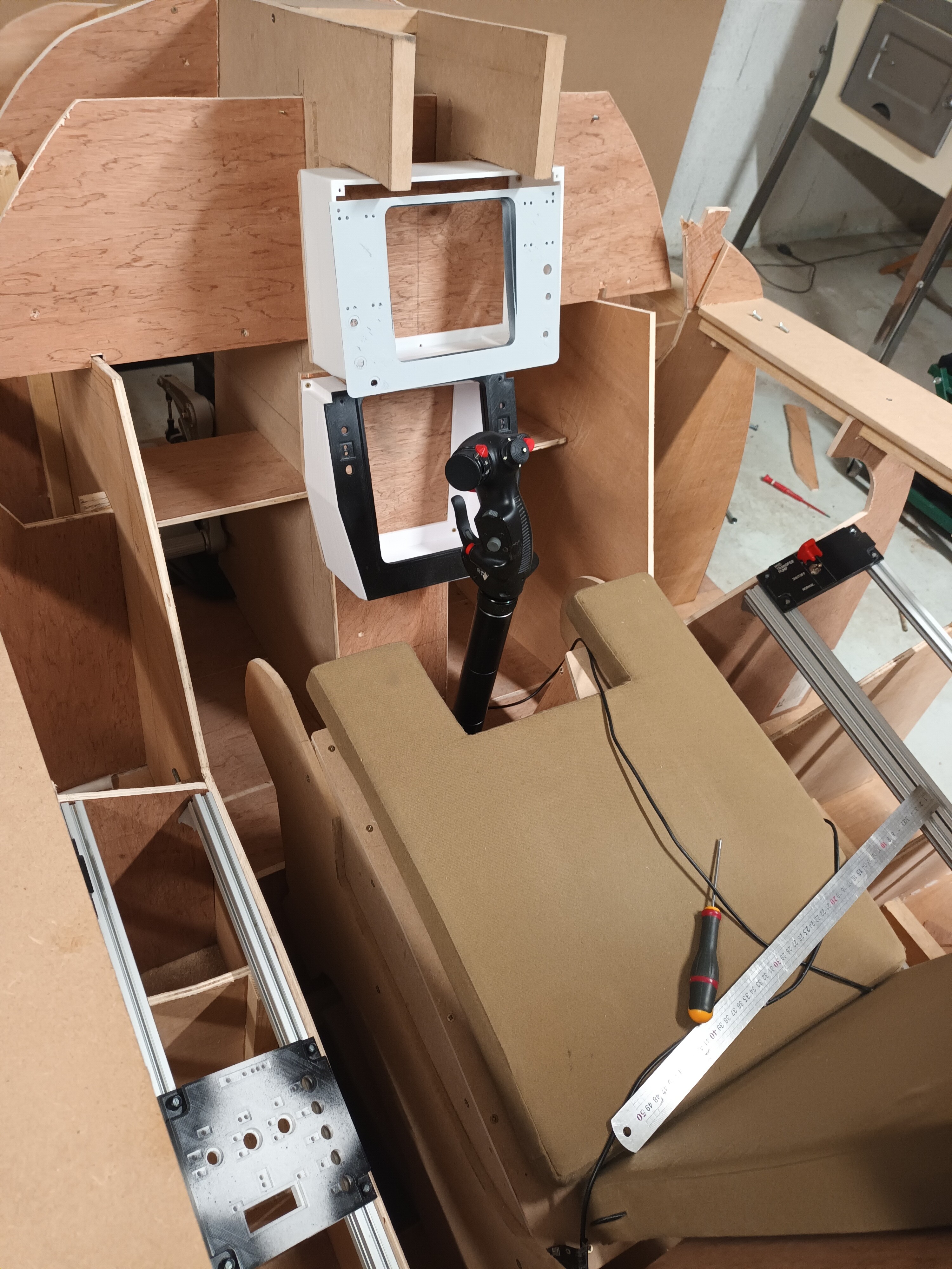
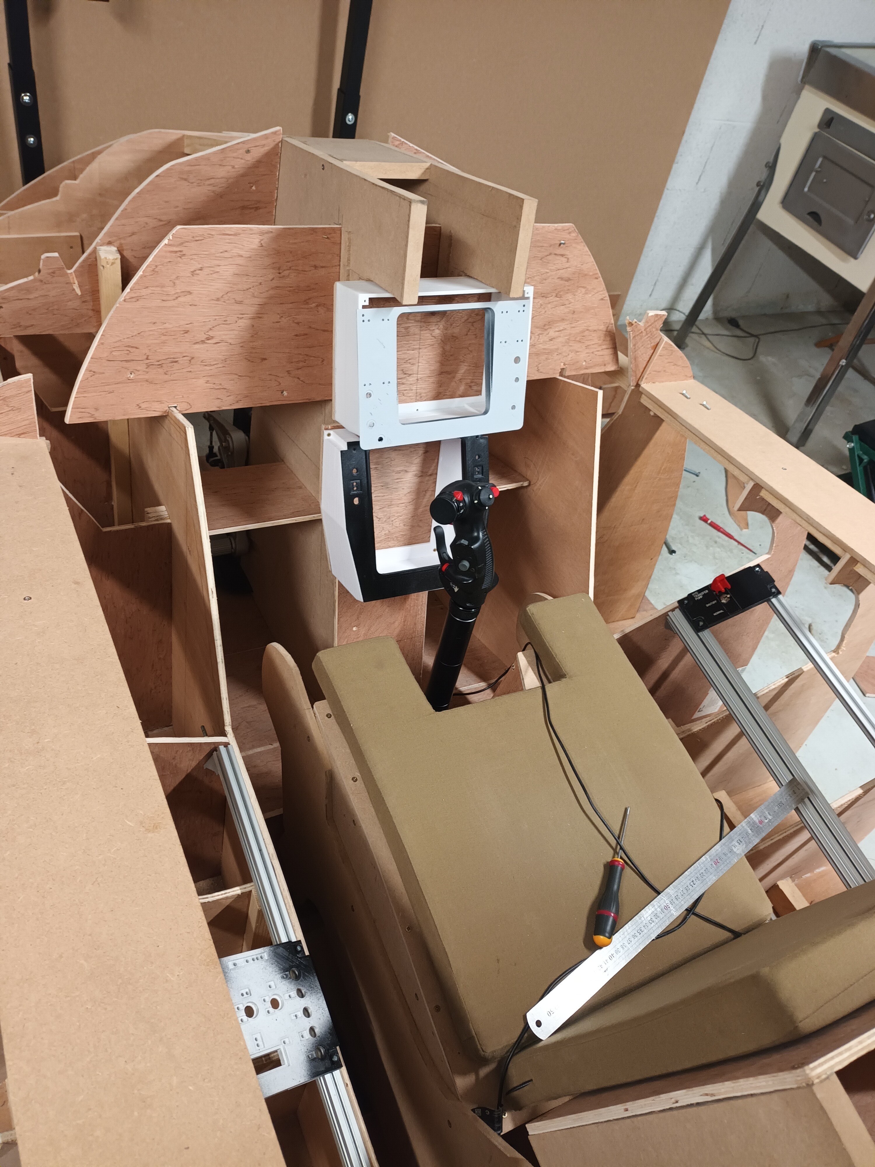
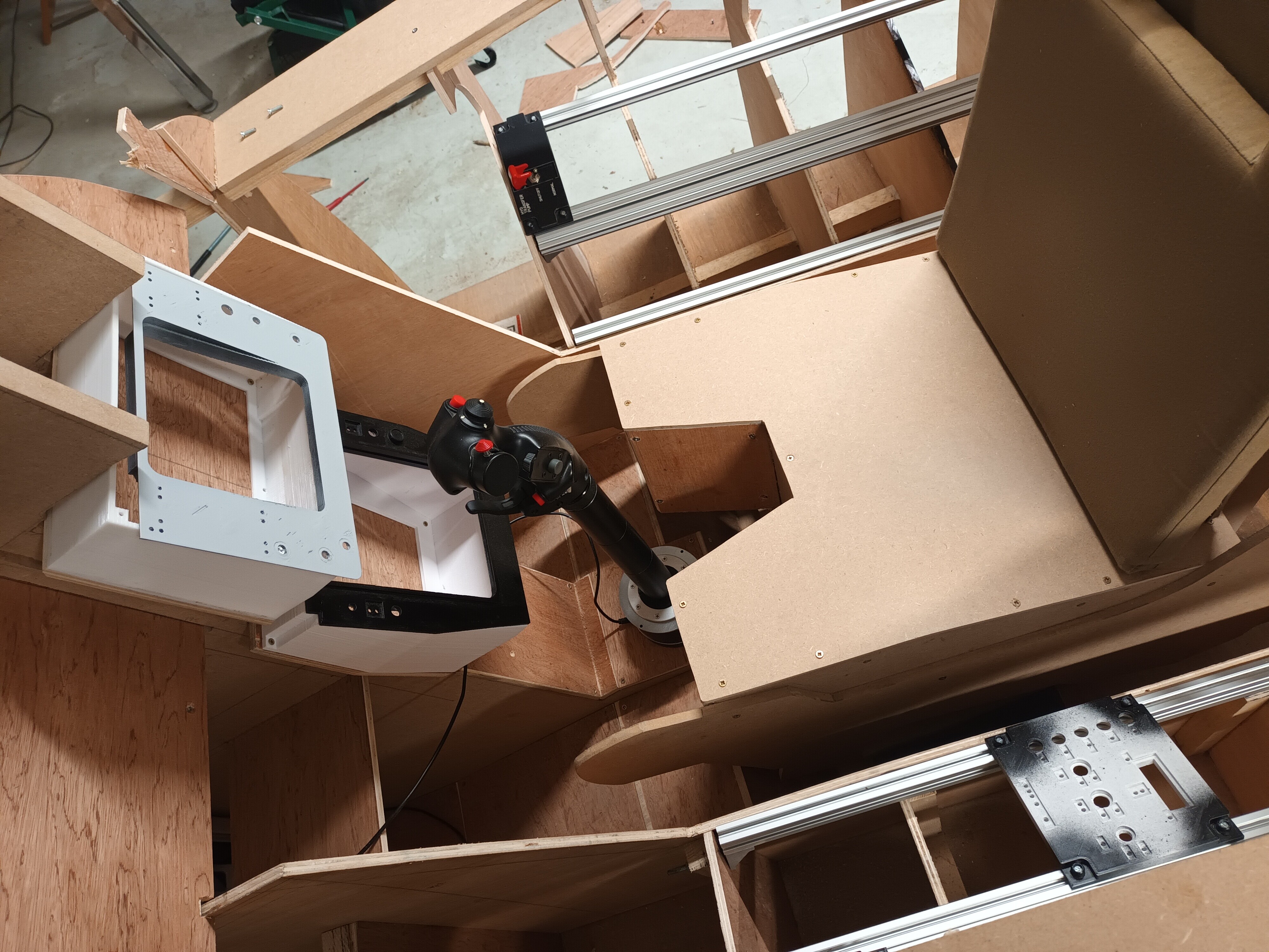
Hi TOMCATERS ! I ve a doubt, and need your advice/experience, like @Jar72 my stick is too close from the HSD , @AusMumbles, @Hagen can you look at my pictures and tell me if my seat isn't too close from the central panel ? i'm thinking about printing a curve extension for my stick , do you recommend an stl ? there are many of them on thingiverse or 3D culte but which one ? Best regards Guillaume imageproxy.jfif

-
@AusMumbles holy…. Amazing ! Guy you made the ejection seat switch !! ?? Can see it on top of your seat !! can we get closer pictures please ? @hagen your lighting system is great !
-
Guys I have modified my wheels casing adding a small system to make some « feeling » when changing the value I will put the stl on the post I made few days ago DF0F1EAB-367D-4EFF-8F3B-903186A79E6C.mov
-
@ITR1102 I look on my pit . Angle of side panel is around 24 Degrees
-
I was going to send it also … that s not a D model .. what’s that ? Where are the weapons controls since the wcp dissepear ? Someone have pictures of an F14 cockpit with this avionic ?
-
HI ITR1102 n i can told you that tomorrow , i will mesure my angle on my structure. I've a question for you : you build the throttle from the 3D cult ? don't you find some problem with some gears ? scale issue ? I print gears , but before i start to build it , it look like some gears are not at the good scale ? and some parts are missing looking at the folder i find on thingiverse . what is the best source to download all parts ?
-
hi guys ! i like to share with you also what i've done i'm almost sure that all of you have done it , even better than me , but here is my "wheel " to control cockpit temperature and lighting system. 473073487_8984741991581509_1729866004211133571_n.mp4 And here are the STL , the wheel 1 is the one you have on the video, the wheel 2 is a modified one with more deeper "edges" , so you can choose , but i prefer the second one. i use some M3 screw with Flat head screw to do not interfer with the wheel. supportpotB v4.stl roue v11.stl roue2 v1.stl supportpot v5.stl
-
@hagen do you think it is possible If I modify a little bit your « hats » to obtain a little bit more space between button ? Like 22 mm ? If yes do you agree to share your sketchup ou 3D fusion file so I can modify it . I do not ask you to do it. I will.
-
Thanks a lot Hagen . And once again good job !!
-
Work in progress ! HUGE!!!! what is the space between each button please ? from center to center ?
-
Hi @Jar72 thanks a lot for the file !! Sorry I did not remember who give me the files at beginning. But thanks lot !! And nice job . Your pit is on the way !!!
-
Hi Ausmumbles ! Yes please this will helps a lot ! really appreciate ! Best regards Guillaume
-
Hi Ausmumbles, again thanks a lot, my pit is liket taht thanks to YOUR work ! you make a very good job with the 3D model. You are right this parts is included in your model, but i used a PDF layout of your model i download from someone else ( i don't remember the name) and this parts is not included, and for the moment i don't find on sketchup how to produce a real size layout of that part . Usually i print the layout and draw it on the wood that i then cut. Do you know how to produce a layout ? Best regards Guillaume
-
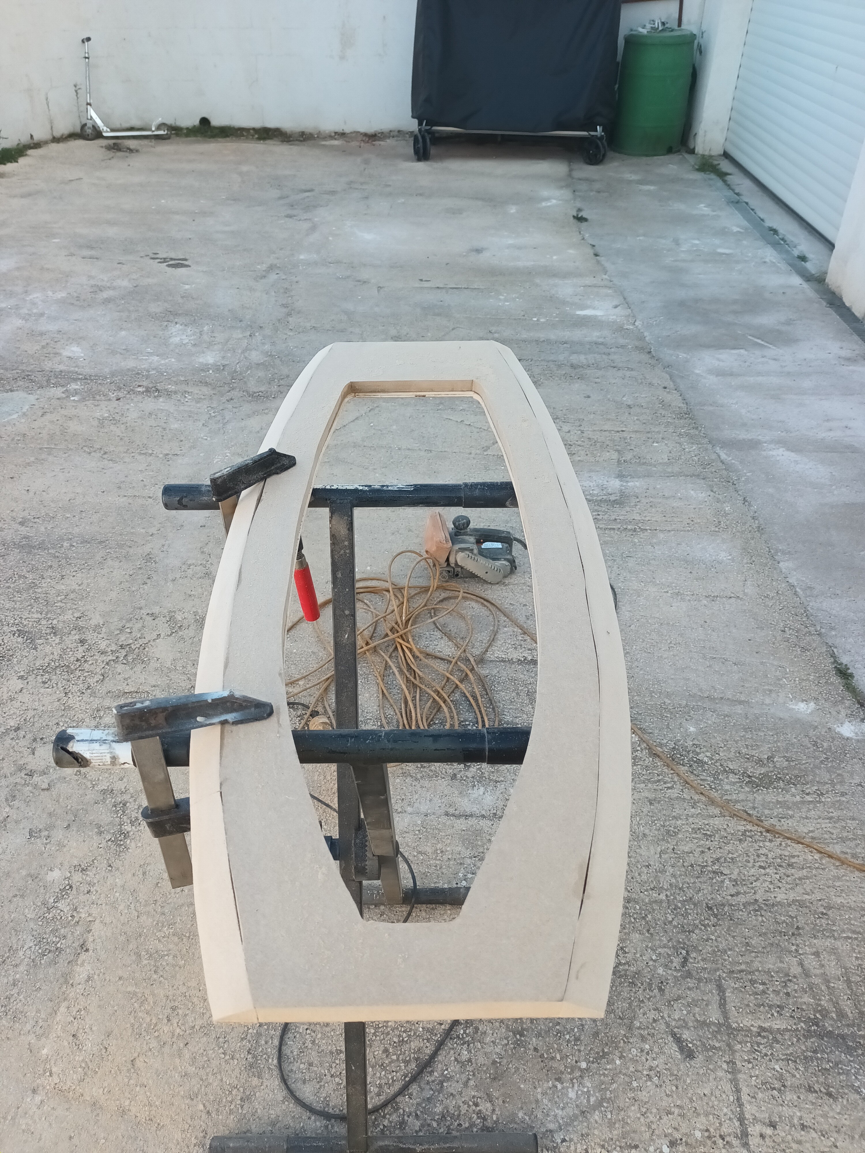
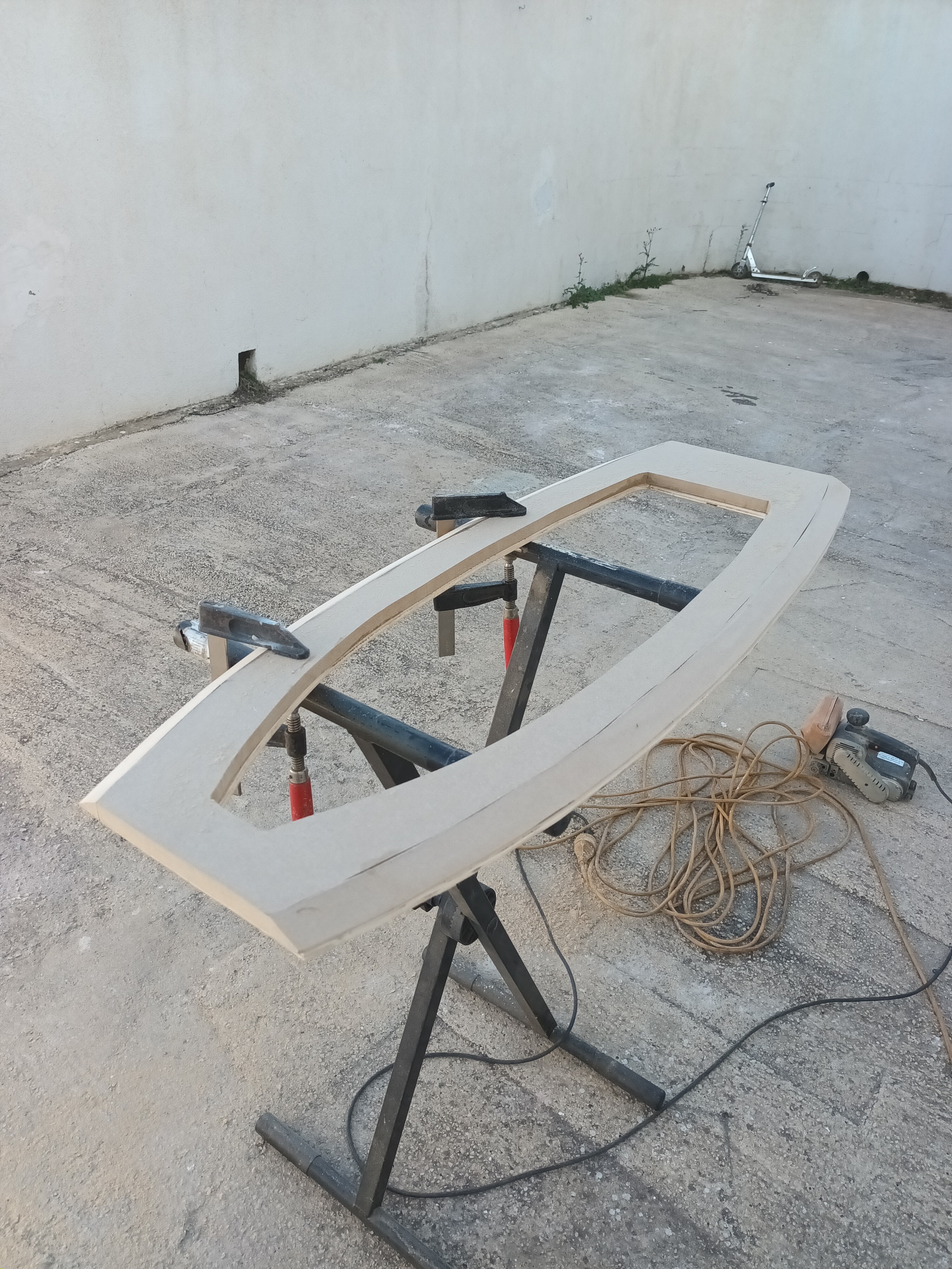
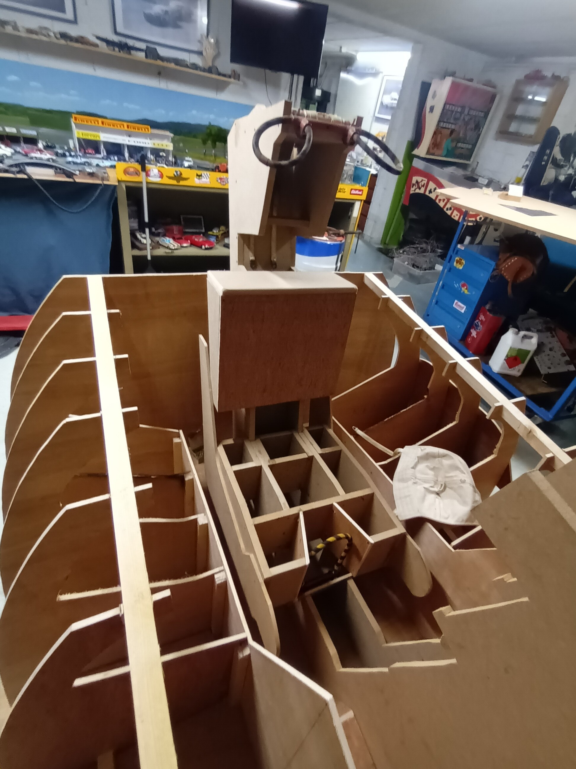
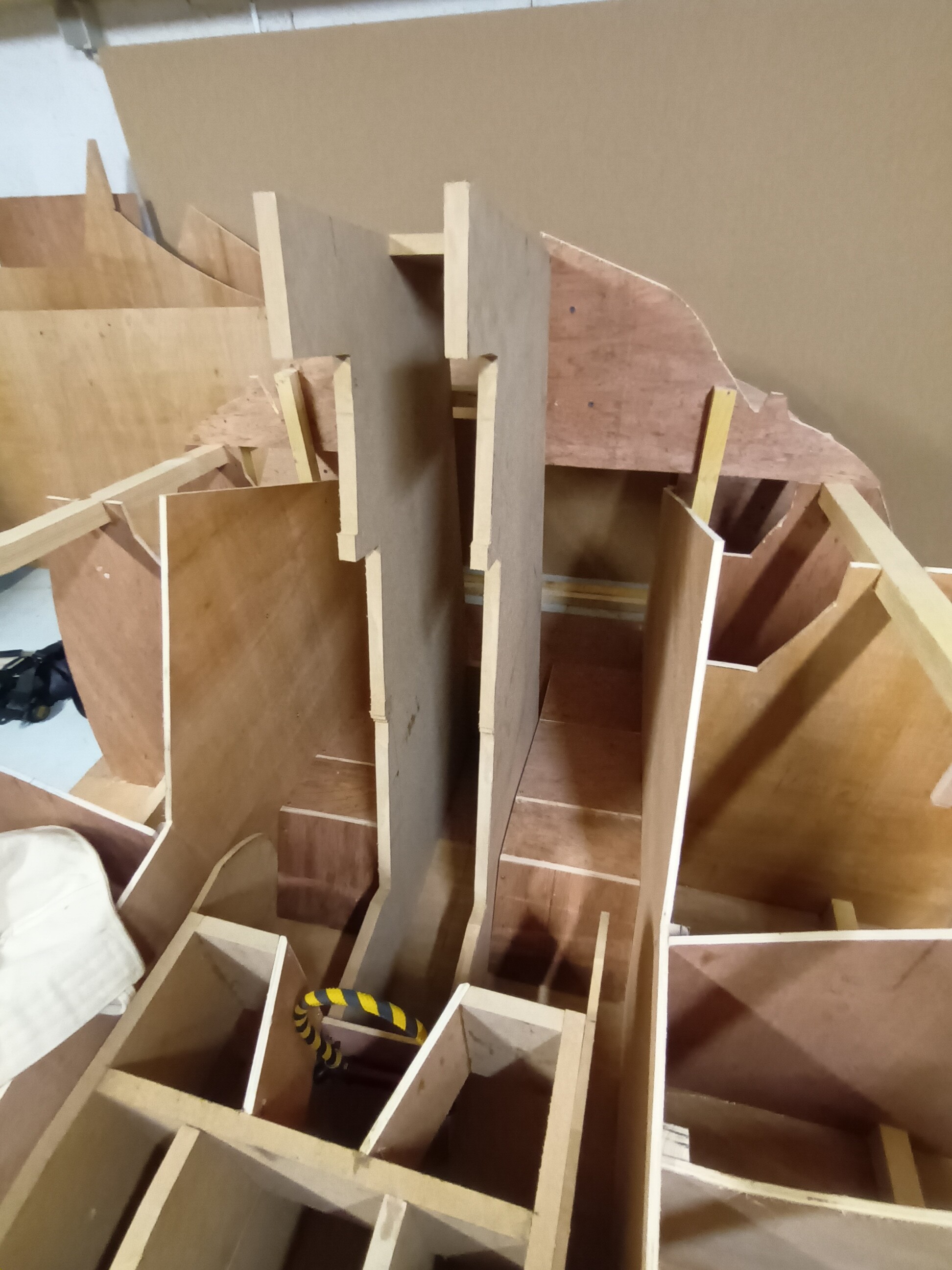
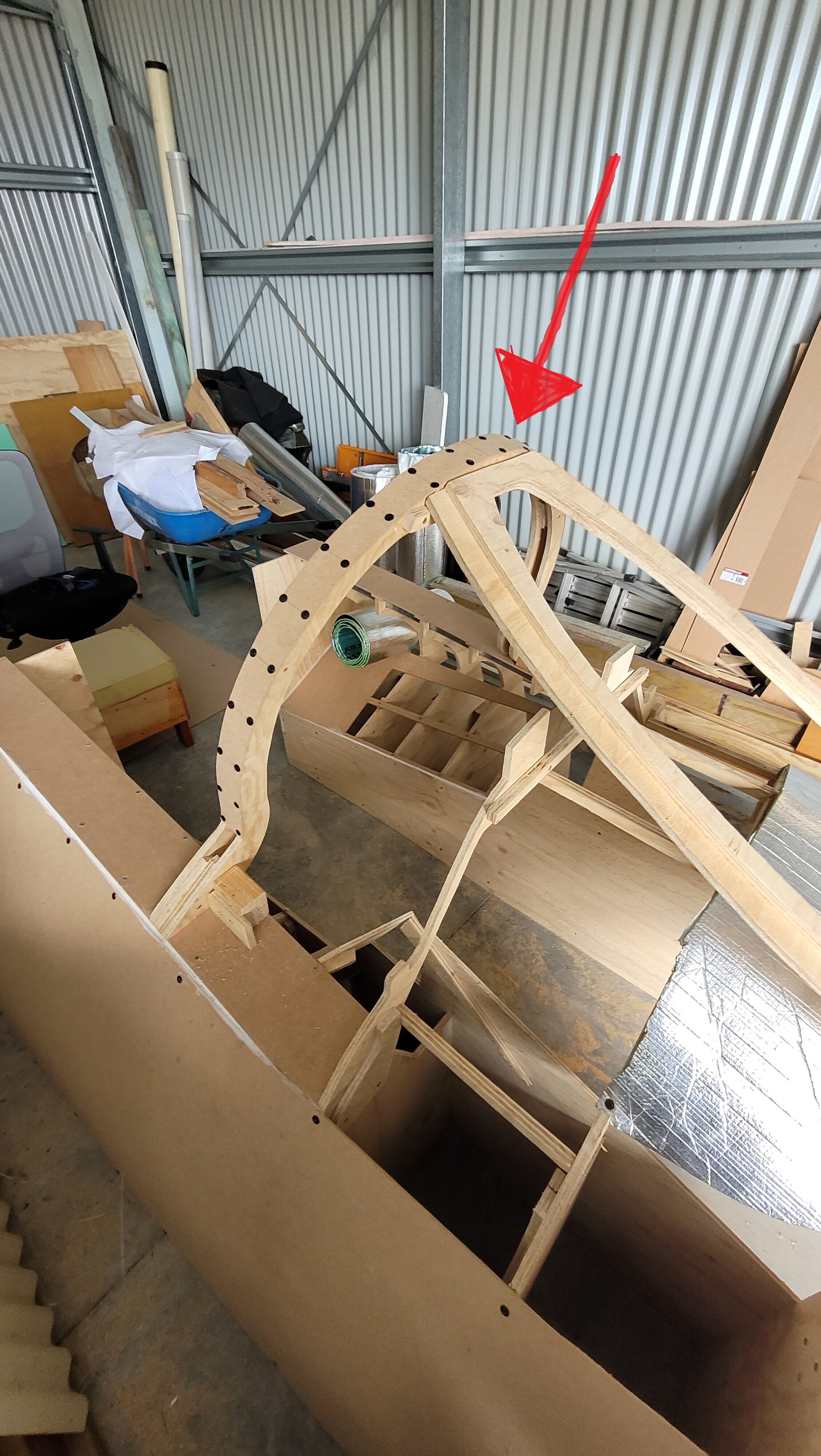
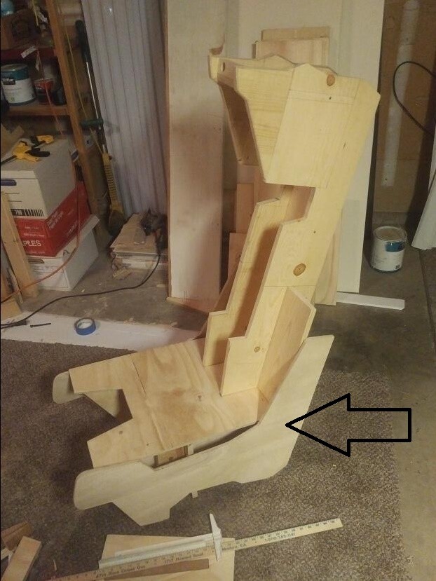
hi TOMCATERS ! here is some news from FRANCE , my pit progress, but i miss the U parts , the vertical one of the windscreen above the instrument panel, i've no plan, no drawing of it ? did someone have a plan of this part ? i've the front windshield part , but not the vertical one. i take a picture of AUSMUMBLES to illustrate with a red arrow Best regards
-
Again thanks a lot Rust for those explanation, i will look at this youtube channel !
-
@Elo and @RustBelt thanks a lot guys for your answer and explanation, i really appreciate, i've never build any analog gauge and have it drived buy and arduino; in my older version of the pit i use the arduino only for some light or display radio frequencies; you are right, i should try. in my previous version i use one big screen to simulate all gauges with helios. Just 2 new question following your thread : Did stepper motor gauge fast enough ? i mean to be accurate while piloting, no "delay " , i.e if i want to stabilize at 10000 ft, will the gauge indicate as fast as on the screen ? i'm sure not, but did you notice some delay ?noticeable ? And another one, the thing about USB C and HDMI display... i don't know this ... what is that ? you can plug a screen with and USB C interface on the PC and have some basic display ? not using the graphic card ? these kind of adapter ? https://www.amazon.fr/BENFEI-Adaptateur-convertisseur-projecteur-Aluminium/dp/B09KXZFS5Z/ref=asc_df_B09KXZFS5Z/?tag=googshopfr-21&linkCode=df0&hvadid=701567717703&hvpos=&hvnetw=g&hvrand=17423419166672598934&hvpone=&hvptwo=&hvqmt=&hvdev=c&hvdvcmdl=&hvlocint=&hvlocphy=9056352&hvtargid=pla-1599437314985&psc=1&mcid=33d9d9b3eac63115aeb1b83f53c178d6&gad_source=1 Sorry for my "basic questions" Best regards
-
Yeah you are right ITR1102 , then the GPU will suffer ..
-
Hi guys! I'm looking very accuratly all your fantastic jobs, but i can't understand something : nowadays we can find screens almost from the size we wants, TOMCAT have a complex instrument panel divided on separate plans. One of the solution is to get one screen for the HSD, one for the VSD, one for the RWR , one for the engine panel ... etc ... but most of the graphic card have a maximum of 4 HDMI slot. How do you deal with this ? what is the solution ? from what i read , do you manage to display the fuel quantity for example on a screen via an arduino ? and you display HSD and VSD with helios via 2 hdmi port of your graphic card ? one of you can makes a drawing of his "instrument panel " display plan ? Best regards Guillaume
-
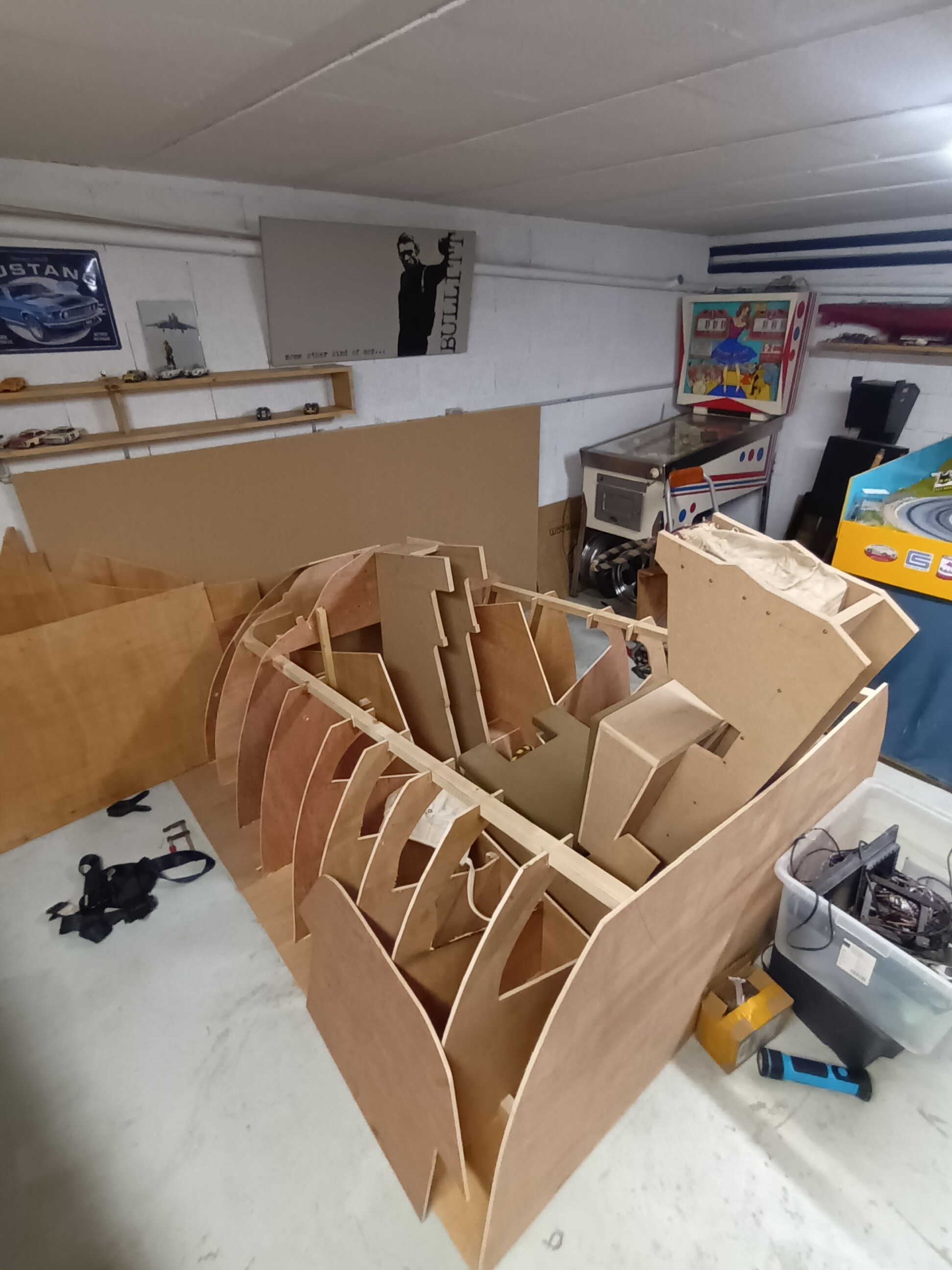
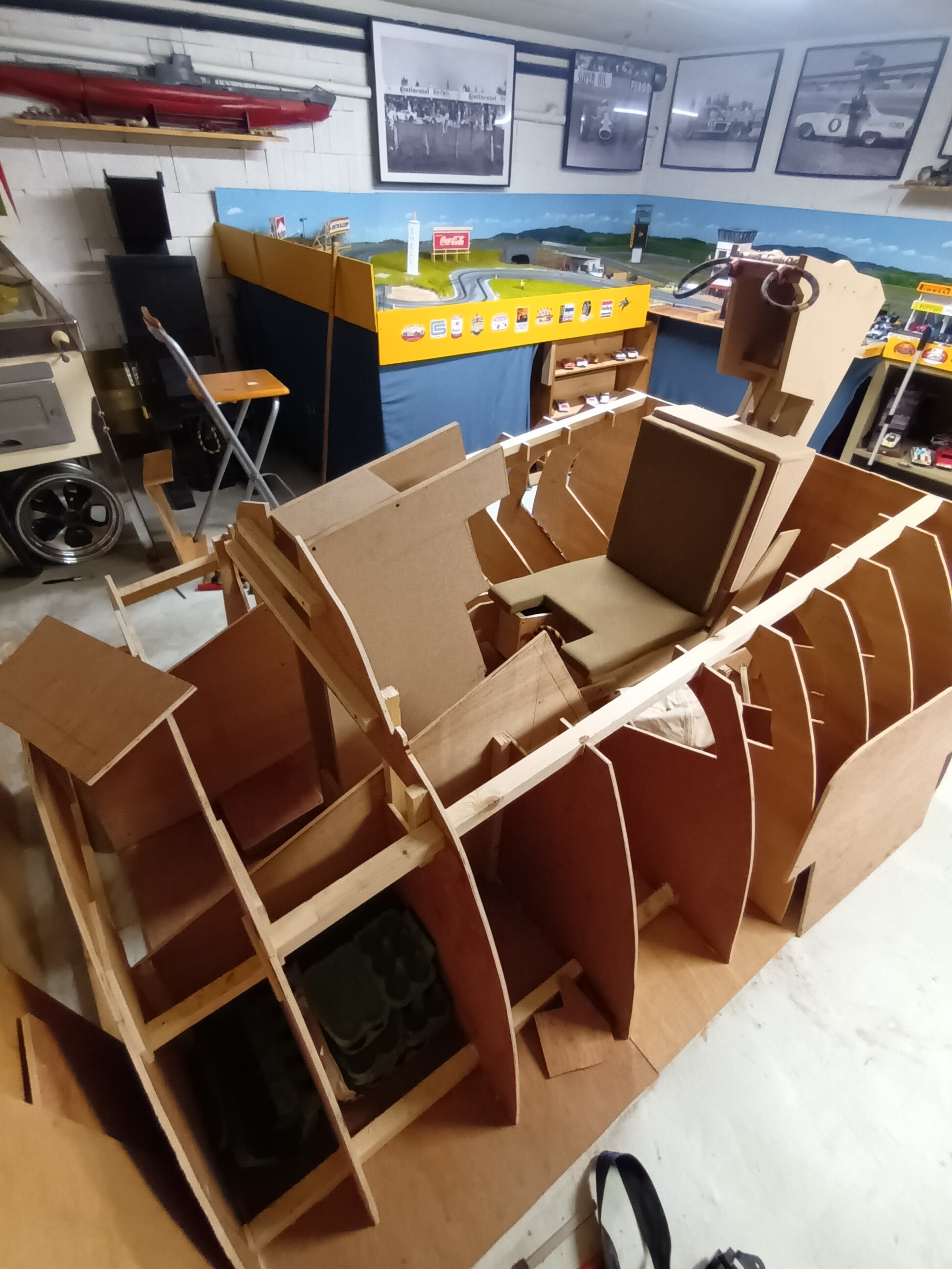
All manual , i print the plan at scale 1 and i cut
-
Work in progress !!
-
@Jar72 Thanks a lot for your answer ! and for the windshield plan !! it will helps me ! for the seat i was speaking of that one :
-
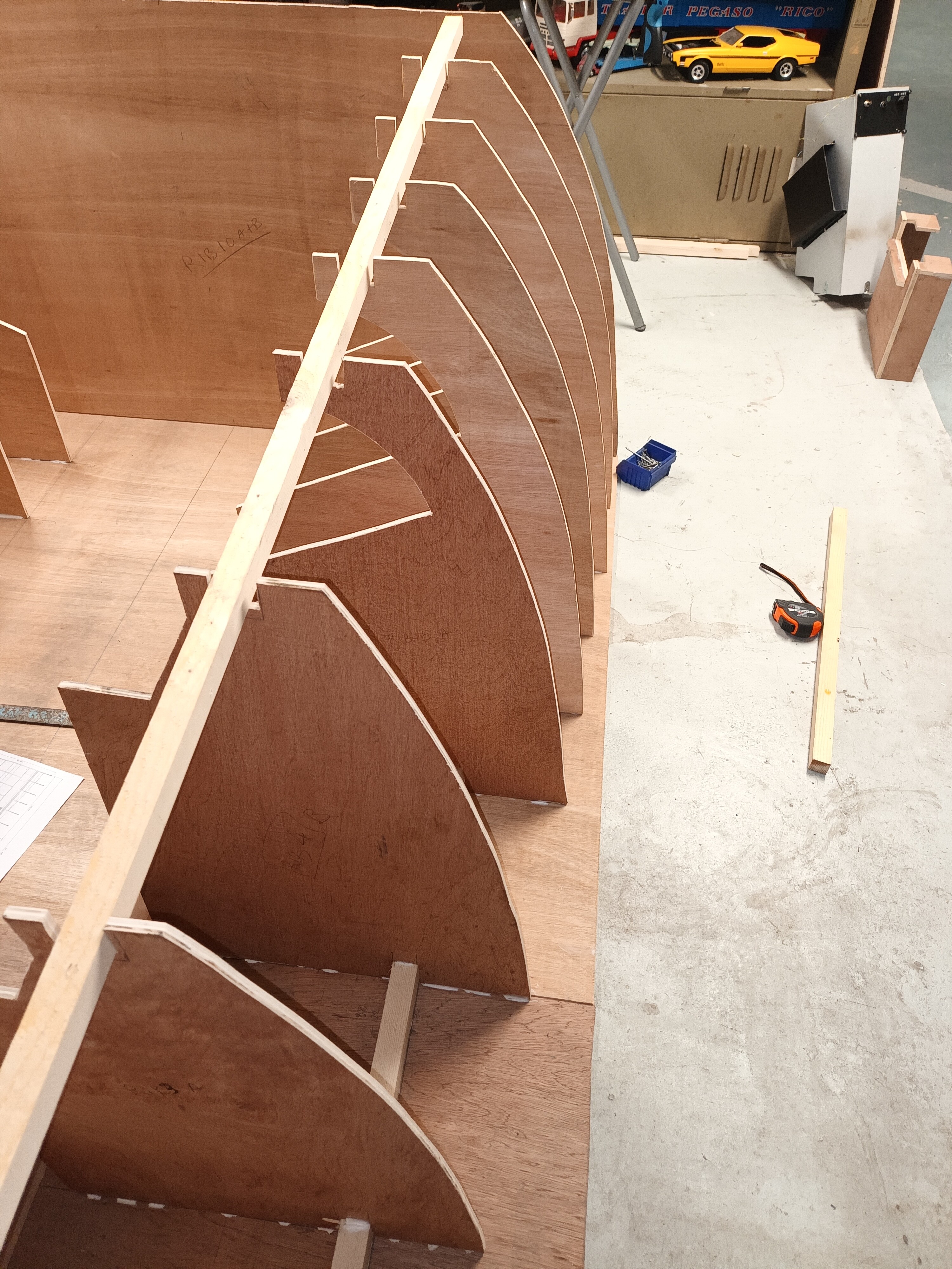
Hi @Jar72 , Thanks a lot for your ZIp of the wonderful mumble JOB But some files are missing, i'm cutting the wood to start my second simpit, but the windshield main frame is missing along with the side of the bottom part of the ejection seat , do you have those drawning please ?
-
i made some progress , all leds works, only the MAX7219 didn't works ; any idea ? also , i cannot change the range of my potentiometer adding to these : DcsBios::Potentiometer pltEmergWingSweepltLever("PLT_EMERG_WING_SWEEPLT_LEVER", A3); DcsBios::Potentiometer pltEmergWingSweepltLever("PLT_EMERG_WING_SWEEPLT_LEVER", A3, false, 0, 185); Why ? thanks forgot the last version of my sketch : /* use '#define DCSBIOS_DEFAULT_SERIAL DCSBIOS_IRQ_SERIAL' instead if your Arduino board * does not feature an ATMega328 or ATMega2650 controller. */ #define DCSBIOS_DEFAULT_SERIAL #include <DcsBios.h> #include <LedControl.h> /* pin 7 is connected to the DataIn pin 6 is connected to the CLK pin 5 is connected to LOAD We have only a single MAX72XX. */ LedControl lc=LedControl(7,6,5,1); /* paste code snippets from the reference documentation here */ //PILOT ARC-159 Frequency void onPltUhfRemoteDispChange(char* newValue) { lc.setChar(0,0,newValue[6],false); lc.setChar(0,1,newValue[5],false); lc.setChar(0,2,newValue[4],false); //true=this is the full stop after digit no 3 lc.setChar(0,3,newValue[2],true); lc.setChar(0,4,newValue[1],false); lc.setChar(0,5,newValue[0],false); } DcsBios::StringBuffer<7> pltUhfRemoteDispBuffer(0x1474, onPltUhfRemoteDispChange); DcsBios::LED pltGunRate(0x127e, 0x8000, 25); DcsBios::LED pltHookLight(0x12ee, 0x0008, 2); DcsBios::LED pltSwCoolOn(0x12d4, 0x2000, 22); DcsBios::LED pltMslPrepOn(0x12d4, 0x8000, 24); DcsBios::LED pltGunRateHigh(0x12d4, 0x0800, 25); DcsBios::LED pltMasterCaution(0x12d4, 0x0080, 23); DcsBios::LED pltMslModeBore(0x12d6, 0x0004, 26); DcsBios::LED pltSeamLock(0x12d4, 0x0400, 27); DcsBios::LED pltFlapsIndLight(0x12ee, 0x0100, 8); DcsBios::LED pltSpdbrkFullLight(0x12ee, 0x0400, 9); DcsBios::LED pltSlatsIndLight(0x12ee, 0x0080, 10); DcsBios::RotaryEncoder pltHsdKnobCrs("PLT_HSD_KNOB_CRS", "-182", "+182", 40, 41); DcsBios::Potentiometer pltEmergWingSweepltLever("PLT_EMERG_WING_SWEEPLT_LEVER", A3); DcsBios::Switch2Pos pltEmergWingSweepltCover("PLT_EMERG_WING_SWEEPLT_COVER", 51, true); DcsBios::Potentiometer pltVuhfVol("PLT_VUHF_VOL", A4); DcsBios::Potentiometer pltUhf1Vol("PLT_UHF1_VOL", A5); DcsBios::Potentiometer pltHudBright("PLT_HUD_BRIGHT", A2); DcsBios::LED pltTacanComandPlt(0x12d2, 0x0800, 48); DcsBios::Switch2Pos pltHudFilter("PLT_HUD_FILTER", 46); void setup() { DcsBios::setup(); //This initializes the MAX7219 and gets it ready of use: lc.shutdown(0,false); //turn on the display lc.setIntensity(0,5);//set the brightness lc.clearDisplay(0); //clear the display //The following series of "lc.setChar" commands are used to display the number 8 in each digit. This allows us to see each that LED segment is actually working. lc.setChar(0,0,'8',false);// The first number...0, means there are no other MAX7219's connected to the one we are using. lc.setChar(0,1,'8',false);// The second number...1, indicates the digit you are sending data too...digit numbering starts at 0. lc.setChar(0,2,'8',false);// The third number in single quotes is the character thats displayed lc.setChar(0,3,'8',false);// The statement... true/false is to turn on or off the decimal point (dp) for that particular digit. lc.setChar(0,4,'8',false); lc.setChar(0,5,'8',false); } void loop() { DcsBios::loop(); }
-
is there someone to check my sketch please ? lot of problems.... /* use '#define DCSBIOS_DEFAULT_SERIAL DCSBIOS_IRQ_SERIAL' instead if your Arduino board * does not feature an ATMega328 or ATMega2650 controller. */ #define DCSBIOS_DEFAULT_SERIAL #include <DcsBios.h> #include <LedControl.h> /* pin 7 is connected to the DataIn pin 6 is connected to the CLK pin 5 is connected to LOAD We have only a single MAX72XX. */ LedControl lc=LedControl(7,6,5,1); /* paste code snippets from the reference documentation here */ //PILOT ARC-159 Frequency void onPltUhfStringFreqChange(char* newValue) { lc.setChar(0,0,newValue[6],false); lc.setChar(0,1,newValue[5],false); lc.setChar(0,2,newValue[4],false); //true=this is the full stop after digit no 3 lc.setChar(0,3,newValue[2],true); lc.setChar(0,4,newValue[1],false); lc.setChar(0,5,newValue[0],false); } DcsBios::StringBuffer<7> pltUhfStringFreqBuffer(0x1248, onPltUhfStringFreqChange); DcsBios::LED pltGunRate(0x127e, 0x8000, 25); DcsBios::LED pltHookLight(0x12ee, 0x0008, 2); DcsBios::LED pltSwCooloff(0x12e2, 0x8000, 22); DcsBios::LED pltMslPrepON(0x12e4, 0x0002, 24); DcsBios::LED pltGunRatehigh(0x12e2, 0x2000, 25); DcsBios::LED pltMasterCaution(0x12e2, 0x0200, 23); DcsBios::LED pltMslModeBore(0x12e4, 0x0008, 26); DcsBios::LED pltSeamLock(0x12e2, 0x1000, 27); DcsBios::LED pltFlapsIndLight(0x12ee, 0x0100, 8); DcsBios::LED pltSpdbrkFullLight(0x12ee, 0x0400, 9); DcsBios::LED pltSlatsIndLight(0x12ee, 0x0080, 10); DcsBios::RotaryEncoder pltHsdKnobCrs("PLT_HSD_KNOB_CRS", "-182", "+182", 40, 41); DcsBios::Potentiometer pltEmergWingSweepltLever("PLT_EMERG_WING_SWEEPLT_LEVER", A3, false, 0, 185); DcsBios::Switch2Pos pltEmergWingSweepltCover("PLT_EMERG_WING_SWEEPLT_COVER", 51, true); DcsBios::Potentiometer pltVuhfVol("PLT_VUHF_VOL", A4); DcsBios::Potentiometer pltUhf1Vol("PLT_UHF1_VOL", A5); DcsBios::Potentiometer pltHudBright("PLT_HUD_BRIGHT", A2, true); DcsBios::LED pltTacanCmdButton(0x1222, 0x8000, 48); DcsBios::Switch2Pos pltHudFilter("PLT_HUD_FILTER", 46); void setup() { DcsBios::setup(); //This initializes the MAX7219 and gets it ready of use: lc.shutdown(0,false); //turn on the display lc.setIntensity(0,5);//set the brightness lc.clearDisplay(0); //clear the display //The following series of "lc.setChar" commands are used to display the number 8 in each digit. This allows us to see each that LED segment is actually working. lc.setChar(0,0,'8',false);// The first number...0, means there are no other MAX7219's connected to the one we are using. lc.setChar(0,1,'8',false);// The second number...1, indicates the digit you are sending data too...digit numbering starts at 0. lc.setChar(0,2,'8',false);// The third number in single quotes is the character thats displayed lc.setChar(0,3,'8',false);// The statement... true/false is to turn on or off the decimal point (dp) for that particular digit. lc.setChar(0,4,'8',false); lc.setChar(0,5,'8',false); } void loop() { DcsBios::loop(); }