lesthegrngo
-
Posts
1245 -
Joined
-
Last visited
Content Type
Profiles
Forums
Events
Everything posted by lesthegrngo
-
I had a sort of similar issue quite a while back that almost made me give up on RS485, where one day it all worked, next day totally non functional. In that case updating the Arduino IDE fixed the issue, I wonder if a recent IDE update has messed with it again? Les
-
I can confirm that using individual devices for the different gauges does really help. If you want to run more than one gauge off a single Nano / Uno / Mega over RS485, as long as they are not very active gauges you can. So on the A-10, hydraulic, fuel, Oxy pressure, Oxy Qty, flap position and cabin pressure gauges are ok where you want to use multiple on one arduino, as they mostly are either virtually static, or move slowly. As a result you won't notice any difference. For the Altimeter, VVI, AOA and ALL the engine and APU gauges, I use one for each to prevent issues I can also attest to using 3 RS485 masters on one Mega, which splits the network into three separate ones, which made my wiring simpler and works great For the U8G2 use, try replacing the 'F' in the sketch code (after 'NONAME') with 1 or 2 - this is apparently the frame buffer, 'F' is 'full' whereas you can choose a lower value. It may help with the memory issue. Here's an example change U8G2_SSD1306_128X64_NONAME_F_SW_I2C u8g2(U8G2_R3, /* clock=*/SCL, /* data=*/SDA, /* reset=*/U8X8_PIN_NONE); to U8G2_SSD1306_128X64_NONAME_1_SW_I2C u8g2(U8G2_R3, /* clock=*/SCL, /* data=*/SDA, /* reset=*/U8X8_PIN_NONE); Cheers Les
-
Hi all, I am looking at replacing my broken Saitek Pro flight rudder pedals. The toe brake return spring carrier broke, which seems to be common, but I was never really happy with them due to the pretty lousy feel. I was tempted to try and make my own pedals, having made lots of sim rig parts for my racing sim, but the fact that I want to make a proper job of the pedal plates themselves plus the time it would take means I'm looking at off the shelf. The TM TPR's are within my budget, and seem to get great reviews. But (there's always a 'but', isn't there...?) my home built rig frame is a bit too narrow for the pedal assembly, which from diagrams on the web I calculate to be a total of 536mm over the pedal plate bolt heads. From what I read, there is no adjustment of the pedal width available short of a brute force mod to the actual pedal and pedal pivot assembly, however it would be good if I can get confirmation - if they were on sale locally I could look at them, but unfortunately I would have to mail order Cheers Les
-
Hi all, sorry for the delay in getting back on this. Thrustmaster's response was to send in the part as 'that particular part is not spareable'. By the time I pay 90 Quid for the service charge, whatever they charge for the spare part and the labour costs and the shipping and taxes, I would be probably be virtually at the cost of a new stick. Shame, I will try to fix it myself and if I can't a new one beckons Cheers Les
-
Just a question, is that so that all your gauges read zero when you return to DCS next time? If so, a simple zeroing code in the sketch will do that, I have it on virtually all my stepper driven gauges, so when I connect all my gauges go to the zero position automatically Cheers Les
-
On the 3 buses for each mega, I have tried it and it works fine, it helped me simplify my wiring a lot Cheers Les
-
My version for the A10 altimeter still relies on using the A4899 stepper, the only device that does. I would be interested in seeing how the code looks for the direct to Arduino version, as I was unable to figure it out Cheers Les
-
You will require an IR sensor like a TCRT5000 connected to the arduino so that when the needle passes it it registers as the zero Cheers Les
-
Good point - if you want it for USB you would replace //#define DCSBIOS_IRQ_SERIAL #define DCSBIOS_RS485_SLAVE 35 #define TXENABLE_PIN 2 with #define DCSBIOS_IRQ_SERIAL //#define DCSBIOS_RS485_SLAVE 35 //#define TXENABLE_PIN 2 and the slave number is what you choose it to be Les
-
This is a really simple code, you do not need a stepper driver and it will make an X27-168 stepper motor display the A10-C Engine 1 Core RPM as long as you connect the four stepper connections to pins 3, 4, 5 and 6 - although you will have to try the four variations to make it work right. It's pretty simple and needs no stepper drive as it is driven directly from the Nano. Please note that I am not the author of this code, that hero is also here on the forum! Cheers Les
-
Well remembered - but this time even with the USB stick it is not working. I've downloaded the latest from the Github page, still nothing. Like I said, on other PC's no problem, just my desktop. I've tried installing in a different drive and location but once it gets to the debug page it closes. Is there an extension it requires to run, like Java or something? Cheers Les
-
Hi all, I use the great tool BoboBear made very regularly, for checking the function of LED's and gauges in DCS Bios sketches. However over the last couple of days it has started playing up on my desktop PC where I do most of my setup work. It still works on the gaming PC, so it is clearly not an issue with the programs or an incompatibility with Windows 10 in general, but it's a pain to have to lug everything over there and connect it up just for testing. I have completely deleted the files and folders, redownloaded all of it and reinstalled, cleaned the registry, but it still doesn't work. It will open up the CMD box, go through the startup, and then immediately shuts down. Anyone got any ideas? It would be good to get it back Cheers Les
-
Thanks, there are a few dotted round the cockpit, and I even have an .stl file for them in case I want to glue one on! Cheers Les
-
I'm starting to think that maybe I was using the environmental test button Vinc mentioned thinking it was for this - it was one of the first things I was trying to make, so probably didn't realise the difference Cheers Les
-
That's the one on the environmental panel, the one I am looking for is the one on the oxygen supply panel, above the oxygen dilution switch Of course, it may be that it is not a test switch at all, and I am getting confused! Cheers Les
-
Hi all, I am certain that in the past there was a DCS BIOS command for the oxygen test button on the oxygen supply panel, but now I am unable to find it. Am I getting confused and there never was one? Cheers Les
-
Hi all, in a separate post I had previously expressed some negative opinions about the Saitek Pro Flight Rudder pedals I have, predominantly with respect to the rather flimsy, wobbly feel that have. Well, yesterday I was installing my center pedestal linking the dash to floor, with the (fake) CB panel on it, and was checking to make sure that there is enough clearance for legs and feet to get to the pedals. In doing so I actuated the pedals as you would normally do, and then *crack*.... and the right hand pedal went limp. It seems that this was the toe brake return spring attachment breaking which is quite a common problem. As a result, I am going to have to open them up and fix the toe brake issue, and will have to do both sides otherwise I will just be doing it again in the coming months. So now I am going to have to do something, and want to explore options on what I can do to improve them in any way that I can while I am at it. A couple of suggestions were raised on the thread where I originally questioned them, but want to canvass you guys as to what can be done to make them better. I want to make them feel more solid, and realistic, so what can I do? Cheers Les
-
Increasing the sensitivity of IR digital position sensor
lesthegrngo replied to lesthegrngo's topic in Home Cockpits
Sorry for the delay in getting back on this I tried a 200 ohm resistor, that seemed to do the trick, the gauge works well with that without risking the pointer fouling on the gauge face. The new PCB is so much better than the old one in every way Thanks as always for the input! Les -
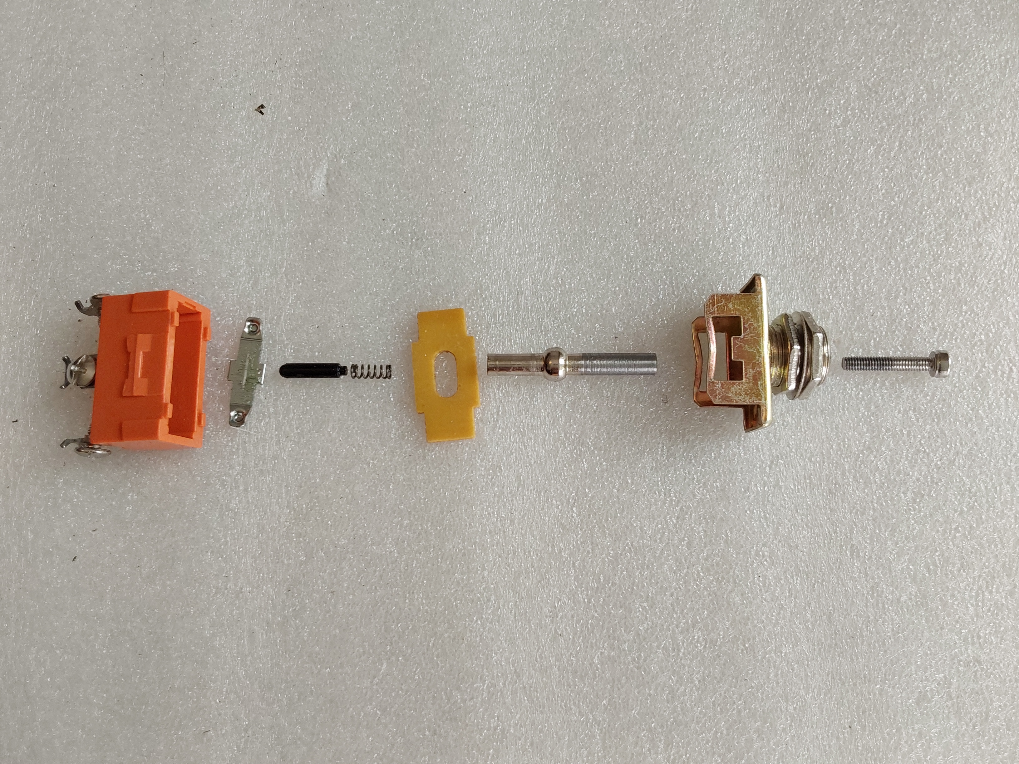
Here's the toggle switch I modified. You can see the right hand side of the lever is machined straight, and I have tapped it with an M3 thread the actual lever is to the right of the yellow plastic plate. It's this plate that makes the switch move in the right plane, but as you can see the lever is machined with a spherical part which then sits inside the top housing on the right. By modifying the plate to make the slot narrower and machining flats on the sides of the lower part of the lever you could prevent the rotation. The problem is that the lower part of the lever is hollow so there is not much there to machine before you break through. The alternative would be to make a plate with a wider slot and either press fit or solder a sleeve onto the lower part of the lever that has anti rotation flats that match the slot width. The plate fits onto the top of the orange housing, meaning that the sleeve would only have to be a few millimeters thick It's doable, I just have to try it. Watch this space. Les

-
Increasing the sensitivity of IR digital position sensor
lesthegrngo replied to lesthegrngo's topic in Home Cockpits
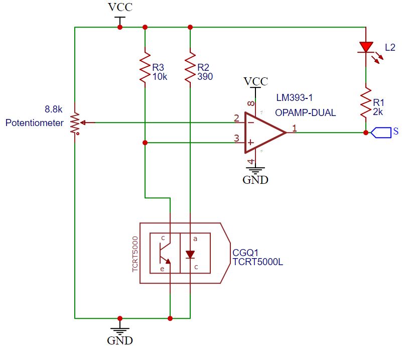
Mylar, that's the stuff. I have a roll of speed tape too, the problem is with it is that it ends up less like a mirror finish due to the way that it conforms to the surface, having a slightly frosted look. I'll see what I can source here I can swap the resistor easily enough to test it but if the worst comes to the worst I will just have to make the pointer (or at least the reflective part) sit very very closely to the gauge fascia By hardware comparator, you mean the Op-Amp, so (referring to the schematic) inputting what would go to the LM393 pin 3 directly to the nano input? Cheers Les -
Increasing the sensitivity of IR digital position sensor
lesthegrngo replied to lesthegrngo's topic in Home Cockpits
Thanks, but if anything bringing it closer makes it work better. I can get it working if I have a distance of 2mm or less between the pointer back and the gauge face, meaning about 4mm in total. I am playing with different materials for putting on the back of the pointer, and obviously highly reflective materials are giving better results. I am going to see if I can find some mirror finish film like the stuff they use for balloons to see if that helps. However I would still appreciate any suggestions about improving the ability to adjust the sensitivity. I'm wondering about the resistor values, whether changing any of those would help, but of course my intrinsic ignorance about electronics means I am probably talking out of my recharge socket (Red Dwarf reference there for those confused...) Les -
Increasing the sensitivity of IR digital position sensor
lesthegrngo posted a topic in Home Cockpits
Hi all I have completed my new Climb and Altimeter gauge PCB, which has four nanos, one each driving two OLED's for the BARO ALT and altimeter displays, one for the climb gauge direct and one via an A4899 stepper using a TCRT5000L IR sensor module to give a zero position. I had previously cannibalised an Arduino IR sensor module with success, but it was a fairly clumsy PCB assembly and also had outputs for the OLEDs requiring a lot of dangling wires. The new one is a lot better and needs only two wires, one RS485 connection and one 12v supply. However the new IR sensor set up is clearly nowhere near as sensitive as the old one, as while it works when tested, once behind the gauge fascia with the slit at zero it is not able to detect the pointer passing in front. I've verified using the following sketch that the digital output does change const int digital_pin = 6; const int analog_pin = A0; void setup(){ Serial.begin(9600); pinMode(digital_pin,INPUT); } void loop(){ Serial.print("Analog Reading="); Serial.print(analogRead(analog_pin)); Serial.print("\t Digital Reading="); Serial.println(digitalRead(digital_pin)); delay(1000); } Obviously the analog reading doesn't change, but if you move a piece of paper about an inch in front of the sensor when not behind the gauge fascia, the digital output goes from zero to 1 verified using the serial monitor. I used the following circuit (attached below) with two minor changes - I couldn't get an LM393 IC, so instead I had to use an LM339, which is essentially the same chip but with inputs for four devices rather than one, but functionally using the correct pins should be identical. The other change was that I could not get an 8.8K trim potentiometer, only a 10K item So I need to increase the sensitivity. It seems that the potentiometer makes very little difference to the sensitivity, there is a slight change but it is minimal. Is there any way to achieve this? Cheers Les
-
Advice requested for a small but irritating soldering issue
lesthegrngo replied to lesthegrngo's topic in Home Cockpits
ok, thanks all. I'll try increasing the iron temperature and test it to see if it helps - it is a small one, deliberately to prevent me cooking stuff! I'm curious as to why it is not mentioned in any of the troubleshooting FAQ's that I looked at on line Cheers Les -
Advice requested for a small but irritating soldering issue
lesthegrngo replied to lesthegrngo's topic in Home Cockpits
Yes, I use one like that, only made from stainless rather than brass - does that make a difference? Cheers Les -
Advice requested for a small but irritating soldering issue
lesthegrngo replied to lesthegrngo's topic in Home Cockpits
Yeah, that's it - little spikes that form as you draw the iron tip away. I've tried cleaning the tip and all the rest of it, but once it forms on a particular joint, most times I end up having to mechanically remove it. The only other way is if it ends up bridging to another connector, then I use a piece of flux coated multicore and the iron to wick it away Les