lesthegrngo
-
Posts
1245 -
Joined
-
Last visited
Content Type
Profiles
Forums
Events
Everything posted by lesthegrngo
-
Environmental panel gauges not functioning
lesthegrngo replied to lesthegrngo's topic in Home Cockpits
All, I redid the sketch from scratch today, starting with a blank sketch and copying across code from working sketches and then splicing in the relevant DSC Bios lines. It works, so all I can surmise is that there is something corrupted in the original sketch. I had a similar issue with an altimeter sketch a few days ago, where it just stopped working. Luckily the code was copied in notepad++ so I used that as a backup. However no matter how hard I looked I couldn't see what the difference between the two sketches were. It also reminded me of when RS485 stopped working, and it turned out it was a glitch with the Arduino IDE So, a couple of lessons learnt, 1) back up any working sketches, and 2) just because you can't see anything wrong with the sketch doesn't mean that you shouldn't suspect it! Hope this helps someone Les -
What material do you print with? I use ABS when printing the few FDM parts I make, which is strong but prone to delamination on thicker parts. Of course, my printer uses 3mm filament which cuts the options a bit Nice work on it all! Les
-
Did the 'file integrity' thing, all good now, thanks Don't know what went wrong Les
-
Thanks, I will give that a go! By the way, a reference to El Botones Sacarino in your username...? Les
-
Hi All, I have the DCS Camera Control Reference Sheet, which tells me that F1 gives the cockpit view, F2 the external view etc, however none of these F keys work. I have not assigned the F keys to anything else, so am confused as to how to get the camera views to change now. Any ideas? Cheers Les
-
VHF AM / FM Frequency 2 and Frequency 3 function DCS BIOS
lesthegrngo replied to lesthegrngo's topic in Home Cockpits
Ok, with the help of VincVega and No1sonuk, who as ever were untiring in their inputs, I finally have it working. It's a bit late to do detail today, but will happily share anything with you all, but just to show here is a video of the (loosely assembled) VHF AM panel. I still have to finish some details on it but 95% of the work has been done Thanks once more to all that helped! Les -
VHF AM / FM Frequency 2 and Frequency 3 function DCS BIOS
lesthegrngo replied to lesthegrngo's topic in Home Cockpits
it's the same, looks like the way the OLED is interpreting the output data I'm puzzled as to why the Freq2 is dealt with differently to the other two Frequency values that change Les -
VHF AM / FM Frequency 2 and Frequency 3 function DCS BIOS
lesthegrngo replied to lesthegrngo's topic in Home Cockpits
Yeah, dry joint on Freq2 Encoder, so that now shows changes on the LCD display. However the OLED display stubbornly refuses to reflect the LCD numeral, it just gives out letters and also as you rotate the freq2 encoder it messes with the Freq1 OLED I'll try and get a vid up here you go Les -
VHF AM / FM Frequency 2 and Frequency 3 function DCS BIOS
lesthegrngo replied to lesthegrngo's topic in Home Cockpits
All, I have the panel 90% working now, but (for the VHF AM panel at least) are Freq 2 and Freq 3 ever anything other than "4" and ".0"? I have the encoders wired for Freq 2 and 3, and no matter what preset you put in and what frequency knobs you twiddle, that's all they ever display, in which case reading the in game data is pointless - I may as well just print 4 and .0 Am I reading that right? Les -
VHF AM / FM Frequency 2 and Frequency 3 function DCS BIOS
lesthegrngo replied to lesthegrngo's topic in Home Cockpits
I have a suspicion that the reason Freq3 doesn't display is that the output would be " .0 " or " 0. " and that is playing hob with the u8G2 displayString command. Maybe I need to be able to convert it to text Les -
VHF AM / FM Frequency 2 and Frequency 3 function DCS BIOS
lesthegrngo replied to lesthegrngo's topic in Home Cockpits
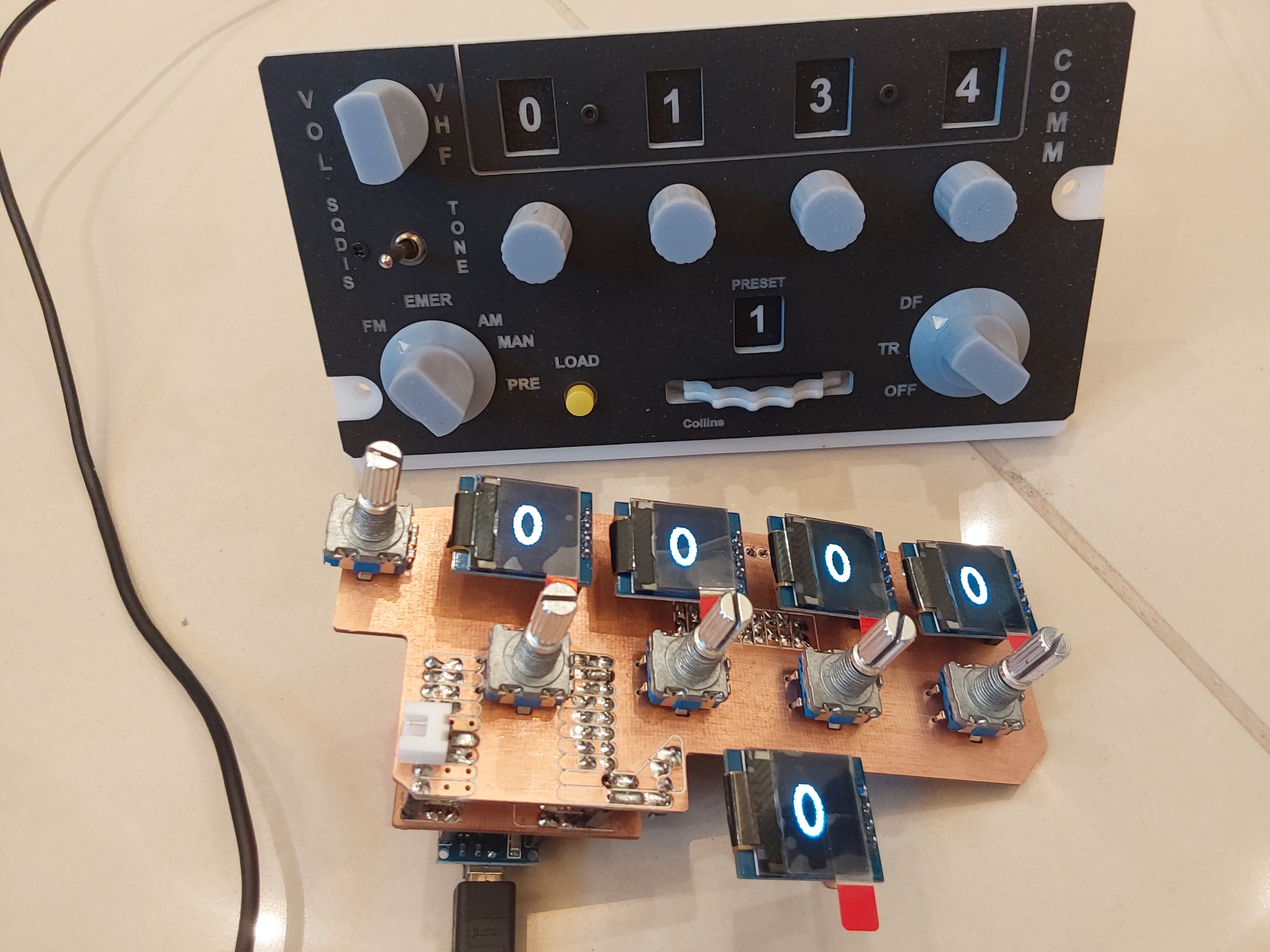
Thanks Here's a pic of the vhf panel with the multiplexed OLED array on its PCB below, with a test sketch (in this case the TISL sketc) to test the hardware. Each OLED will display the particular frequency, or at least that's the intention!
-
VHF AM / FM Frequency 2 and Frequency 3 function DCS BIOS
lesthegrngo replied to lesthegrngo's topic in Home Cockpits
On an LCD screen via a PCF8754 board it does display, but not on these 0.66" u8G2 OLEDs - which is what I have chosen unfortunately. There are some that use the Adafruit SSD1306 library instead of u8g2, I suspect they would be easier to work with Trouble is no-one ships them to Qatar u8g2 also needs 328 Nanos due to the library size, so not a wonderful choice Tomorrow I'll show pictures so you can see why I'm looking at individual digits, there are five oleds per panel Les -
VHF AM / FM Frequency 2 and Frequency 3 function DCS BIOS
lesthegrngo replied to lesthegrngo's topic in Home Cockpits
I kept on with this, but it seems the u8g2 library is a bit fussy. Not sure why that should be, but it will do four of the five strings Probably some minor detail, but got me scratching my head Les -
VHF AM / FM Frequency 2 and Frequency 3 function DCS BIOS
lesthegrngo replied to lesthegrngo's topic in Home Cockpits
Thanks, the sketch below worked for Freq2 although the result was unexpected - it displayed the letters IS #define DCSBIOS_DEFAULT_SERIAL #include <DcsBios.h> #include <Arduino.h> #include <U8g2lib.h> #include <Wire.h> U8G2_SSD1306_128X64_NONAME_F_SW_I2C u8g2(U8G2_R3, /* clock=*/SCL, /* data=*/SDA, /* reset=*/U8X8_PIN_NONE); // All Boards without Reset of the Display R3 refers to 270 deg text rotation void setup(void) { u8g2.begin(); DcsBios::setup(); } int WHF2freq2 = 0; void onVhfamFreq2Change(unsigned int newValue) { WHF2freq2 = (newValue); u8g2.clearBuffer(); u8g2.setFont(u8g2_font_logisoso38_tr); u8g2.drawStr(0, 80, WHF2freq2); // 0 left, 0 top bottom appx 100 u8g2.sendBuffer(); delay(1000); } DcsBios::IntegerBuffer vhfamFreq2Buffer(0x118e, 0x00f0, 4, onVhfamFreq2Change); void loop() { DcsBios::loop(); } However the same would not work for Freq3 bizarrely, couldn't get anything to display Les -
Hi all, just working the multiplexer sketch for the five OLED's I am using for the VHF radio panels, and I am a bit confused as to the way that Freq 2 and 3 are output. Freq 1 and 4, plus preset have integer strings as outputs, yet 2 and 3 has 'gauge position' shifting by 3 up to 255 as the outputs, yet the OLED should be displaying a number Sounds like I should be mapping the output to an integer, but somehow that doesn't feel right. It also has the frequency select encoder input, which reinforces that for me Can anyone explain what this should be doing? Les
-
I posted a thread linking to my GrabCad uploads that have a number of my 3d printable files you can download for free. I suspect some of those would be suitable when I get in front of my computer I will link it Here you go https://grabcad.com/library/miscellaneous-3d-files-for-a10c-cockpit-parts-for-dcs-world-1 Les
-
In one of my occasional (and probably ill-advised) forays into other forums to try and find solutions to issues I have developing new or improved panels, it was pointed out to me that there should be a 120 Ohm resistor between the A and B pins of the master, and apparently over the pins in the 'last' device in the network. Since my network looks like one a drunken spider web, it won't have them at the end, but should I be putting in a resistor over the mega master A and B pins? Les
-
All, using the data in the DCS BIOS below, I cannot get the gauges to function either in game or using Bobobear's testing debug program void onOxyVolumeChange(unsigned int newValue) { /* your code here */ } DcsBios::IntegerBuffer oxyVolumeBuffer(0x1132, 0xffff, 0, onOxyVolumeChange); void onCabinPressAltChange(unsigned int newValue) { /* your code here */ } DcsBios::IntegerBuffer cabinPressAltBuffer(0x1134, 0xffff, 0, onCabinPressAltChange); I have tested the gauges using RENG fuel flow to make sure that they work and are correctly wired and pins called out, so it seems to be that these callouts are not functioning Have they been updated or changed? Cheers Les
-
Thanks Vinc - you must have found that out the hard way! I'll give that a go Les
-
Not enough HDMI outputs on Graphics card
lesthegrngo replied to lesthegrngo's topic in Home Cockpits
Fantastic, on it's way (via son number 2 who will be visiting soon) Another (probably stupid) question. I don't want to hamstring this by using a USB cable that will affect it, I assume a USB 3.0 extension cable will be required but am struggling to find any locally, at least not advertised as such. What specs do I need to look for? Les -
Thanks! Looks easy enough too Cheers Les
-
Not enough HDMI outputs on Graphics card
lesthegrngo replied to lesthegrngo's topic in Home Cockpits
Cool, thanks for the feedback - is it this one? if so I'll get it https://www.amazon.co.uk/gp/product/B09BJWGPXR/ref=ox_sc_act_title_4?smid=A3P5ROKL5A1OLE&psc=1 Les -
All, a pretty minor niggle, but would be nice to fix it I have wired up a push button straight to an arduino (pin 9 in this case) with the other side of the switch going to ground for the TACAN test button I have tried both these DSC BIOS Lines and it just won't light the test light (test light checked in Bobobears debugger) DcsBios::Switch2Pos tacanTestBtn("TACAN_TEST_BTN", 9); DcsBios::ActionButton tacanTestBtnToggle("TACAN_TEST_BTN", "TOGGLE", 9); Pin 9 is allocated to nothing else, I have checked that the arduino is electrically connected and no shorts Is this functioning for others? Les
-
I have been told that there should be a resistor between the A and B pins at each slave and reference to the RS485 schematics online shows this. I have not got any, is this something I need to do? it won’t be difficult to do, but before I do I would need to know whether it would be necessary and if so what value cheers Les
-
That’s a new one on me, never heard that term before. I assume also that trying to update the library is going to be beyond me, so I’m happy to simply use the ProMicro boards for non-Rs485 uses; there are still quite a few, including a dash mounted volume control that needs an arduino if I was to ask what ‘bit-banging’ was, would I regret it?! cheers Les