lesthegrngo
-
Posts
1245 -
Joined
-
Last visited
Content Type
Profiles
Forums
Events
Everything posted by lesthegrngo
-
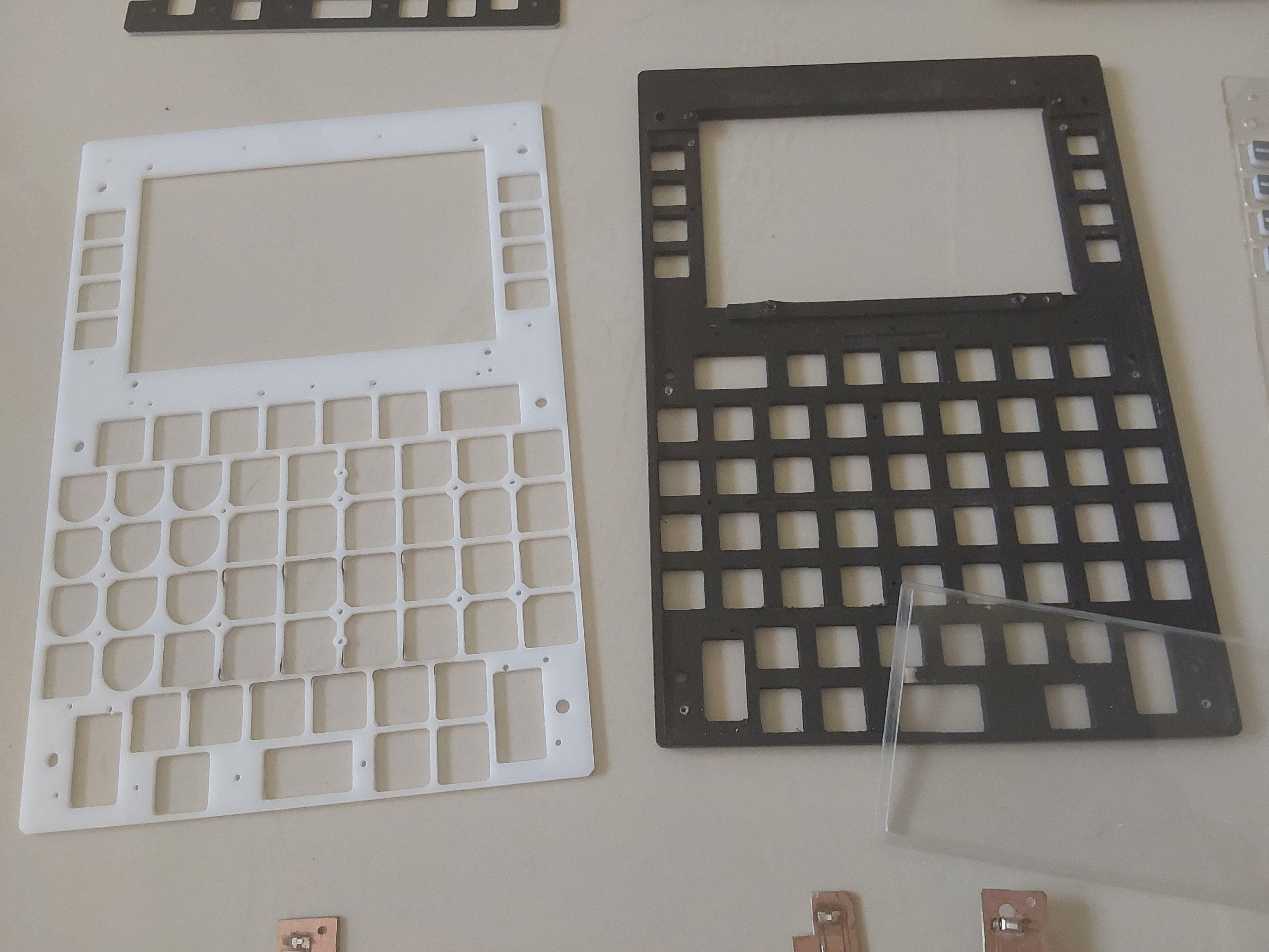
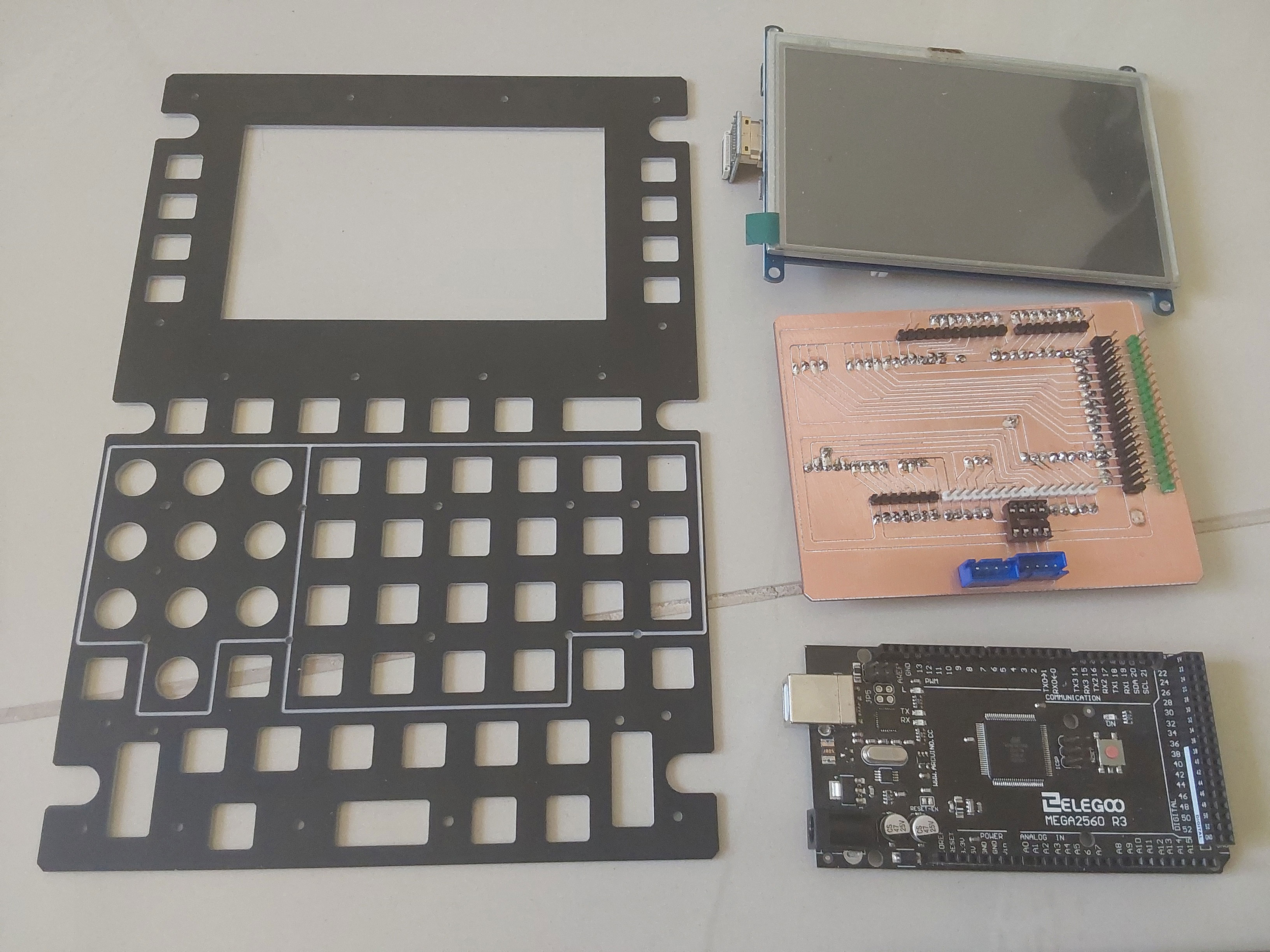
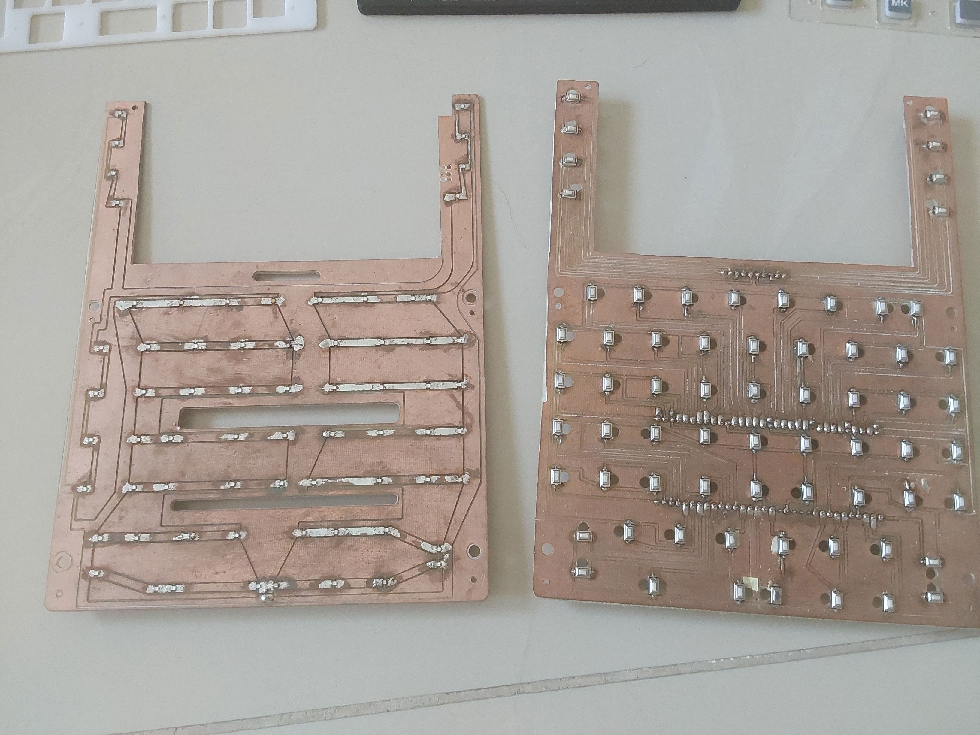
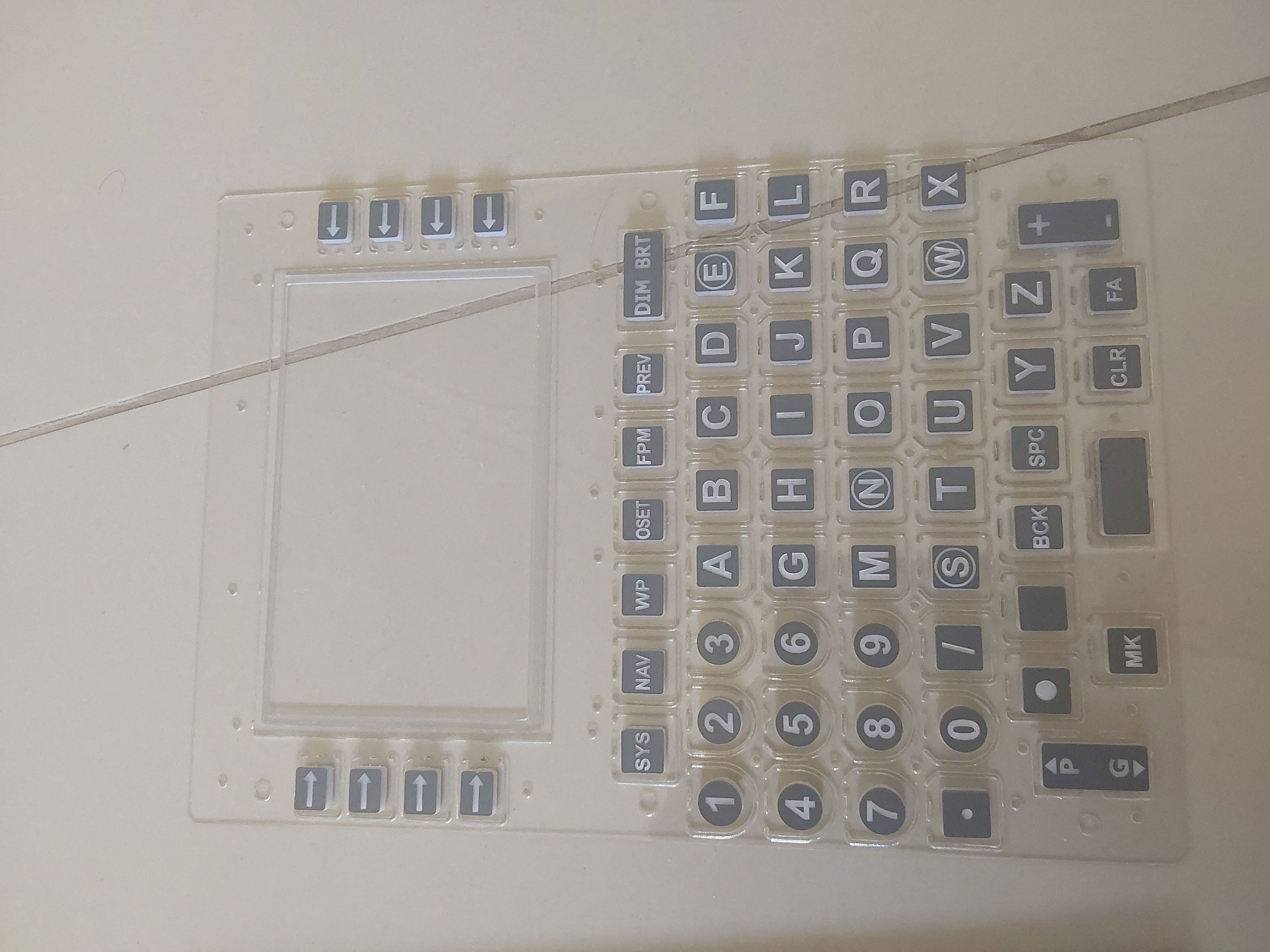
Here's the progress on the CDU update using a 5" HDMI LCD screen, and a direct to slave mega circuit board. The second PCB is the key lighting that goes behind the switch PCB. I need to just fettle the fascia key apertures to ensure they are all smooth, Cheers Les

-
3D Print file repository thread for home cockpits
lesthegrngo replied to BIGNEWY's topic in 3D Printing for DCS
3D modelled Virpil Mongoos T-50 CM2 base so that you can use to integrate the base into your own cockpit https://grabcad.com/library/virpil-mongoos-t-50-cm2-base-1 Les -
3D Print file repository thread for home cockpits
lesthegrngo replied to BIGNEWY's topic in 3D Printing for DCS
Here are some miscellaneous A10 button and switch files plus a few other bits and bobs https://grabcad.com/library/miscellaneous-3d-files-for-a10c-cockpit-parts-for-dcs-world-1 https://grabcad.com/library/a10c-knobs-for-dcs-world-based-cockpits-1 https://grabcad.com/library/a10c-knobs-solidworks-files-1 https://grabcad.com/library/a10c-knobs-2 Les -
Thanks Vinc - I knew I had, as well as being a coding wizz you also clearly know how to use the search function better than I do! @No1sonukAs for problems with the Mega as a slave, you are correct in that there were issues when I tried to use it for the A10-C warning light panel. In USB guise the sketch was running all the lights perfectly, whereas with the RS485 it would only illuminate a percentage of them at a time. You put it down to possible 'bit-banging' My intention is to use a spare mega for switch inputs only as I imagine there is less processing needed and so it won't have the issues that I got with the WLP. I'm redoing my CDU so that all the main panel buttons are operated by the Mega Only one way to find out.... Les
-
Hi again all - I know that I have asked this before and after about half an hour of unsuccessful searching I've decided to just ask the question again - what TX RX pins on a Mega are used for DCS Bios as a slave? I believe it is TX0 and RX0 Cheers Les
-
Got it, thanks - as it happens I must have downloaded it before and forgotten, as it was already there! Cheers Les
-
QR Mounts for swapping sim gear (awesome product)
lesthegrngo replied to Hotdognz's topic in Home Cockpits
Ok, they are 3D printed? Cheers Les -
Hi guys, I want to check that the DCS Bios control references I have are the latest ones, as it is a while since I checked. I installed the latest DSC Bios from here https://github.com/dcs-bios/dcs-bios/releases When I open the DCS Bios web interface and click on the control reference tab, I get the Metatdataend and Metadatastart parts, but when I click on them I don't get any where as they seem to be empty. I have a offline version but it is old, like maybe 5 years old so I suspect that it has been superseded. Can anyone point me to the correct location? Thanks Les
-
QR Mounts for swapping sim gear (awesome product)
lesthegrngo replied to Hotdognz's topic in Home Cockpits
Thanks for this link - I know what you mean about when you specialise on the rig, mine is set up for the A10 and has no commonality with other aircraft. Unfortunately for me it is too late in the day to do major work to make it universal, but this type of thing is still useful where you have certain parts of the rig that are used for other purposes, like the joystick What material are they made from? Cheers Les -
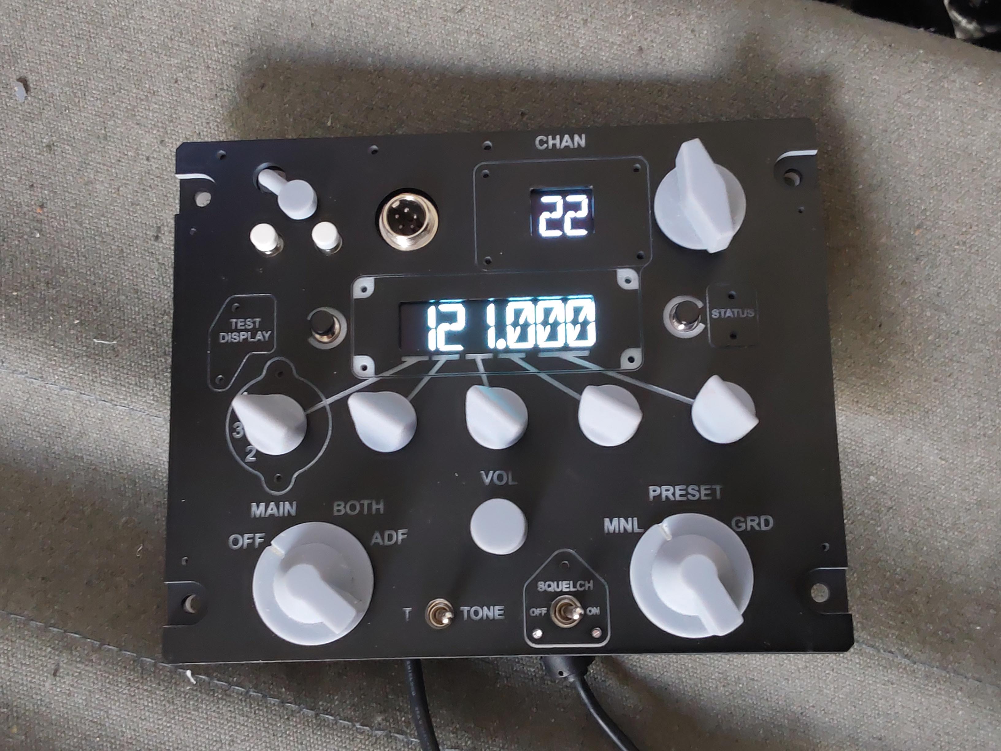
I'm waiting for a few parts that I sent out to make for the pedals that are too big to make at home, so I turned my attention to the UHF radio panel to keep me moving forward You will see in a separate thread that I had a bit of a song and dance getting the larger of the to OLED panels to display correctly, but with Vinc and Outbaxx's help I managed to get it up and running fine. In the end I opted to split the displays over two Nano boards as I needed the extra pins anyway for all the rotary encoders and switches. I have a 3D printed load cover assembly to add to it, though I don't think that I will be making it a switched part, at least not in this iteration. It's a level of complexity that I think is unnecessary for my use. The OLED displays look a bit blurry in this picture, not sure why, but in real life they are very sharp and clear. I will probably play with the frequency font size to reduce it by a pixel or two in height so that it has a bit more border around it. Unfortunately u8g2 doesn't have the ability to scale fonts which would have made this more easy, but it's not a huge task to make a new font once you have been shown how Also, looking at those 3D printed knobs, they are unpainted but I think I need to paint them a darker shade of grey; they look a bit toy like Cheers Les
-
Hi, you cannot have two separate things called 'LED masterModeAa' You have both a switch and an LED calling out the same - rename one Les
-
Remember that most, if not all, of our cockpits are 'stand off' replicas, which means they are always - in some way or another - factually incorrect. This is not for any other reason that in most cases we have to accept the limitations of what is possible with the means, technology, resources and time at our disposal. You make this to suit your needs, and if a panel is 5mm to small, or the button shape is wrong, or it doesn't work... well as long as you are happy with it it won't matter. We will be very happy to see how you get on and help in any way we can, plus enjoy seeing what you make. I wish I could make another rig, either MiG 21 or 23, but I think my wife would kill me, so I will watch your build with interest and not a little envy! Les
-
ok, thanks for the feedback! Cheers Les
-
I use ones similar to this https://www.ebay.com/itm/142839449947?hash=item2141e5095b:g:kdgAAOSwl4NbKoMC&amdata=enc%3AAQAIAAAA8Iv%2Bzo0WujepzUWIvnqO%2BVgzqParG%2BIBe04rPUHGFFtcU5E6pv4plPREHovd7%2FlVK2EhcWSPmnbBPaSu7usBCGeUDYiwdjQGlwXwscXA34YIS9617MEb%2Fr8Fqx4MckvamvZvV6iYxVZJBw98s8rYD9jn%2Bf7OS%2FqZbTGBZwEvKI8xr2IJvdYarUWdWxdezDAdKuOO6SWMKOy%2BT9PyEWeLoZ7YPmCyqGsJjEefZzlFmiMLJU8wVKmdmID0C9qgkvNeW0Sk8Uw6OMq1MYbn0bohdeN2FJz1%2Fq4siysr9Lys%2FhbTvJo9PZUk3mAd3rRqER%2FIYQ%3D%3D|tkp%3ABk9SR9bmp5z6YQ there are some bigger ones that have 6 poles which can be used to make three way On-On-On switches too. They feel similar to the ones on the Warthog base, although you will find that they are a bit variable in the feel, some feel slightly less positive than others and some can be a little gritty in their action. Despite this they are a good starting point, not least because they are pretty simple and can be taken apart to modify them. There are probably some more expensive ones out there on which these cheap copies are based, but these work well enough for my purposes Les
- 1 reply
-
- 1
-

-
How curious - was it more than one unit that you tried? Cheers Les
-
Thanks - the reason for looking is the greater memory, which means better performance for some of the graphics stuff like the OLEDs Les
-
Guys, is the Nano Every compatible with RS485? Cheers Les
-
Here you are for anyone that is interested. This sketch displays the UHF frequency on a 2.08" OLED and the UHF Preset on a 0.66" OLED with 14 Segment LCD type fonts sized to match Cheers Les 208OLEDUHF_with_go_wait_SEG14_LCD5_plus_066_OLED.ino
-
You might want to check the resolution that the particular monitor that shows that MFCD is set up in Windows Extended desktop Cheers Les
-
Well, a lot easier than I thought, I managed to make two instances of the OLEDs and it worked first time. I’ll have to make a second smaller font to match the smaller OLED, but that should be easy now I’ve learned how to do it Les
-
Ok, all, job done! I found another font that had the decimal point in it, and used Fony to basically redo all the numerical characters and decimal point to suit my sketch. And boy am I happy at how it turned out! The characters look great, the spacing of the characters is perfect for my fascia, and it works perfectly with the Nano. For anyone interested I have included the sketch below for download, remember that this is for the 2.08" SH1122 OLED but you can probably use the guts of it to suit another OLED. Now, just because I like a challenge I am going to see if I can get a 0.66" i2C OLED to run from the same Nano. Once more, thanks to Vinc and Outbaxx for their help on this Les 208OLEDUHF_with_go_wait_SEG14_LCD5.ino
-
Thanks Vinc and Outbaxx, I finally got it working My bdfconv files were not appending the headers with "u8g2_font_" hence the error for the callout. Once I figured that out and added "u8g2_font_" in front of the font name the fonts I was creating started working. So it is now showing the correct numbers and at the correct height, I will have to play with the actual bitmaps a bit to make them nicer. However it is a bit weird that there is no full stop / decimal point included in the font, and when you go to a font editor, the character space is blanked out that corresponds to the decimal point. Unfortunately that is a necessary glyph, so my next task is how to incorporate it in the font Cheers Les
-
Here's the entire .c file, is this all there should be? Cheers ****EDIT**** added the .bdf file too Les SEG14.c DSEG14Classic-Bold-54.bdf
-
I ran it again today, this time I have this const uint8_t SEG14[31] U8G2_FONT_SECTION("SEG14") = "\0\0\2\2\0\0\0\0\0R=WO\66\0\66\0\0\0\0\0\0\2\0\0\0\4\377\377\0"; I must have done something wrong last night, but this looks much more like your version However I am getting compiling errors, so how the sketch calls out the new font is obviously my next issue Using this sketch #define DCSBIOS_IRQ_SERIAL //#define DCSBIOS_RS485_SLAVE 48 //#define TXENABLE_PIN 2 #include "DcsBios.h" #include <U8g2lib.h> #include <Wire.h> const uint8_t SEG14[31] U8G2_FONT_SECTION("SEG14") = "\0\0\2\2\0\0\0\0\0R=WO\66\0\66\0\0\0\0\0\0\2\0\0\0\4\377\377\0"; U8G2_SH1122_256X64_2_4W_SW_SPI u8g2(U8G2_R0, /* clock=*/ 19, /* data=*/ 18, /* cs=*/ 16, /* dc=*/ 17, /* reset=*/ 15); // Enable U8G2_16BIT in u8g2.h void onUhfFrequencyChange(char* newValue) { u8g2.firstPage(); do { u8g2.clearBuffer(); //u8g2.setFont(u8g2_font_inb24_mr ); u8g2.setFont(U8G2_FONT_SECTION); u8g2.setCursor(10, 60); u8g2.print(newValue); } while(u8g2.nextPage()); u8g2.sendBuffer(); } DcsBios::StringBuffer<7> uhfFrequencyBuffer(0x1180, onUhfFrequencyChange); void setup() { u8g2.begin(); DcsBios::setup(); } void loop() { DcsBios::loop(); } I am clearly not using the correct syntax for the callout. Also, I must be missing some callouts, here are the error messages F:\Users\LES\Documents\Arduino\208OLEDUHF_with_go_wait_SEG14_font\SEG14.c:7:7: error: unknown type name 'uint8_t' const uint8_t SEG14[31] U8G2_FONT_SECTION("SEG14") = ^~~~~~~ F:\Users\LES\Documents\Arduino\208OLEDUHF_with_go_wait_SEG14_font\SEG14.c:7:25: error: expected '=', ',', ';', 'asm' or '__attribute__' before 'U8G2_FONT_SECTION' const uint8_t SEG14[31] U8G2_FONT_SECTION("SEG14") = ^~~~~~~~~~~~~~~~~ F:\Users\LES\Documents\Arduino\208OLEDUHF_with_go_wait_SEG14_font\208OLEDUHF_with_go_wait_SEG14_font.ino: In function 'void onUhfFrequencyChange(char*)': F:\Users\LES\Documents\Arduino\208OLEDUHF_with_go_wait_SEG14_font\208OLEDUHF_with_go_wait_SEG14_font.ino:39:16: error: 'U8G2_FONT_SECTION' was not declared in this scope u8g2.setFont(U8G2_FONT_SECTION ); ^~~~~~~~~~~~~~~~~ Multiple libraries were found for "U8g2lib.h" Used: F:\Users\LES\Documents\Arduino\libraries\U8g2 Not used: F:\Users\LES\Documents\Arduino\libraries\U8g2_Arduino-master Not used: F:\Users\LES\Documents\Arduino\libraries\U8g2small exit status 1 Compilation error: unknown type name 'uint8_t' The instructions I read on the web say 'just drop the .c code into the the sketch....' !! The problem is that there often an expectation that everyone who reads it will have in-depth programming knowledge, as there is obviously more to it Cheers Les
-
Last post for today as I am running out of time and braincells! The SEG14.c file is the following /* Fontname: -FontForge-DSEG14 Classic-Bold-R-Normal--54-410-96-96-P-420-ISO10646-1 Copyright: Created by Keshikan Glyphs: 0/39 BBX Build Mode: 0 */ #include "ucg.h" const ucg_fntpgm_uint8_t SEG14[31] UCG_FONT_SECTION("SEG14") = { 0,0,2,2,0,0,0,0,0,82,61,87,79,54,0,54, 0,0,0,0,0,0,2,0,0,0,4,255,255,0,0}; When I copy the text in, predictably it compiles with an error saying no file with the name ucg.h exists, which of course des not at least where the SEG14 file was created. Am I supposed to be looking for it somewhere? Cheers Les