SquidgyB
-
Posts
30 -
Joined
-
Last visited
-
Honey, I developed FFB joystick (DIY)
SquidgyB replied to propeler's topic in PC Hardware and Related Software
Ah, I see. Yep, I've worked through a lot of variations to get where it is now and never quite figured out what was wrong, the only way to work around it I've found that consistently works is just to not use the second axis! I've got RJ45 breakouts with each signal wire paired with a ground wire, shielded enclosures, toroids on the motor cables routing cables as best I can away from each other... As for the Due, FINO does have an "experimental" branch for the Due, I haven't fully tested it but it can be flashed and shows up in Windows as a joystick - but I have a plethora of Arduino, RPi and teensy controllers, so one way or another I'll make it work hehe! -
Honey, I developed FFB joystick (DIY)
SquidgyB replied to propeler's topic in PC Hardware and Related Software
@theperson Nice work! You said that downgrading the firmware helped with SPI issues? These have plagued my setup throughout, to the point that I've ordered two separate single-axis ODrive clones to get around the issue - Axis1 seemed to have SPI_COM_FAIL errors on calibration every time while Axis0 stayed ok. I tried with tri-state buffers but these didn't seem to help with the dropouts, though they seemed to work as the data was still being passed on when checking SHADOW_COUNT. At the moment I've got some jitter on both encoders, where it wasn't present when I was building a few months ago - I suspect I might have some alignment issues on the magnet/motor, so I'll have a bit of a re-think of the encoder enclosures as they were a bit... hastily built, shall we say. Right now I have it all set up as a simple "return to center" stick, pedals and throttle all ready, so I just need to add the Arduino Due (which has enough com lines to speak to two ODrives simultaneously) and bodge together some FINO/ODrive Arduino example code - all the code you've posted is going to come in *VERY* handy for that, and I thank you greatly for providing it. I've also given up on the 4-motor configuration I was hoping for - two hoverboard motors is absolutely enough. I'm not sure what the strength of the motors is currently running at, but I've dialled it down a lot, and the grip mount (VKB Gunfighter MKIII) and stick seem a little bit flexy when pushed to the far diagonals - not really enough to worry about, but enought to make me think I'd really like a solid metal grip... -
Honey, I developed FFB joystick (DIY)
SquidgyB replied to propeler's topic in PC Hardware and Related Software
Depends on how comfortable you are with fabricating tbh - in my case I tried to simplify the mechanics to the point that no CAD was needed - the gimbal is the most complex part and admittedly needs some basic machining to make, but it's not overly complicated. mostly off-the-shelf parts which have been modified/carved into shape. Mine's direct-drive from the motors to the gimbal, and uses the hoverboard motors both as the means of powering the system, as well as mounting, bearings and shafts - so no need for gears/belts etc, just a relatively simple MDF box (which I've further reduced in size compared to the previous pics/vids I posted) to which the motors are bolted along with the aforementioned gimbal. I'll get some more pics soon to show the latest state. @propeler Your current iteration looks totally amazing, that silver tower looks glorious! -
Honey, I developed FFB joystick (DIY)
SquidgyB replied to propeler's topic in PC Hardware and Related Software
I finally managed to get the encoders working correctly with the ODrive without having to enable a second SPI line - the trick in my setup was to use a tri-state buffer for the MISO lines from the encoder and to move the CSn pins from GPIO_3/4 to GPIO_6/8 (GPIO_4 in particular seemed to give me issues) - I've now successfully calibrated and saved the settings and can turn on the ODrive and go straight to CLOSED_LOOP_CONTROL, without the need for any endstop mechanics at all, which makes me happy Would you be able to share a brief overview (or just a software list) of the way you created your custom firmware? I'm very intrigued by your previous comment that all the configuration is done via visual tools - does this extend to the USB interface (showing up as a FFB HID device, providing axis information and passing the forces to the motor controllers) and motor control from the STM chip as well? -
Honey, I developed FFB joystick (DIY)
SquidgyB replied to propeler's topic in PC Hardware and Related Software
@propeler Could I ask you for a favour? Would it be possible to get a copy of your pre-made firmware with these SPI changes? If not, could you help a little with the changes? I see these lines in spi.c which I think are the ones which need modifying: I think I'd also need to remove the lines to initialise the ABI pins as they are set by default, which I think is this section in tim.c: ...am I on the right track, or am I barking up the wrong tree? Any help is *greatly* appreciated -
Honey, I developed FFB joystick (DIY)
SquidgyB replied to propeler's topic in PC Hardware and Related Software
Aaaaaaah, that would explain it - as of last night I managed to get SPI sort of working - I added 10k resistors between 3.3v and SCK, MISO and the two CSn's and this seemed to calm things down a bit (getting shadow count that made sense, no SPI errors), BUT... Still having motor calibration errors which seemed to cause SPI errors. This always happened after trying to calibrate, so I'm guessing the motors were interfering with the SPI data and knocking it off kilter until a full power cycle was done. So, the changes you made to run SPI over the alternate pins - I assume that's through modifying the source code and building your own firmware version from that? -
Honey, I developed FFB joystick (DIY)
SquidgyB replied to propeler's topic in PC Hardware and Related Software
I'm wondering if anyone here had issues using AS5048A encoders via SPI and the ODrive, and if so (or not, as the case may be), what circuit did you use with respect to filtering noise out? I've had the TLE5012 encoders working with ABI, but I'd really like the absolute reading rather than depending on mechanical/hall effect switches as endstops - but all my attempts (now using RJ45 connectors, shielded ethernet cables and prototype PCBs have left me with rising SPI errors rates and very occasional shadow count readings being picked up... Specifically, I'm wondering what resistors and capacitors were used and how they were connected to allow two encoders over SPI, sharing SCK and MISO respectively between the two and running CSn separately to each encoder (as I understand it should be done). -
Honey, I developed FFB joystick (DIY)
SquidgyB replied to propeler's topic in PC Hardware and Related Software
It was a bit of an iterative process, so not as simple or straightforward as it could have been as I was trying to re-use parts and materials I had to hand as well as parts I purchased which didn't really turn out to do what I wanted them to... Top and bottom are a linear bearing shaft mount for an 8mm shaft, with the bearings knocked out (they didn't allow smooth rotational movement) - I used a small lathe to turn the inner diameter of an aluminium tube to slot snugly over the linear bearing mount and allow bearings to fit snugly in the tube (the tube and shaft is what I'm holding to move the gimbal). Between the two linear bearing mounts are two 8mm x 25mm x 25mm blocks of aluminium, with a central 8mm hole in each 25mm x 25mm face and 8mm shafts press fitted/JB welded into the holes - these form the "x" axis, whereas the "y" axis is also an 8mm shaft vertically (going through the linear bearing mounts) with a shorter 8mm shaft (the actual "y" axis) soldered and JB welded across perpendicularly. The two 8mm x 25mm x 25mm blocks are then sort of chamfered on the inside to allow the "wiggle shaft" to rotate just enough to allow the gimbal to not lock on diagonal movement (my original design using the propshaft spider fell foul of the same issue you encountered in your first attempt, I believe - locked to the cardinal directions and no diagonal movement at all). The design is fairly symmetrical top and bottom, but the whole thing did need a bit more machining than I initially intended, but as you can see from the pedals, I'm not scared of a bit of DIY fun times (and it "allowed" me to justify the purchase of a small lathe, much to my partner's chagrin! :D) When I get the gimbal out later I'll post some pics as I think that will help a lot with the explanation above... Overall, in terms of machined parts, the internal SK016's (the four on the central gimbal part) needed some chamfering on the corners and rounding of the top of the mounts, a pair of aluminium tubes needed the internal diameter changed to slot over the linear bearing mounts, and also to a different diameter to hold the bearings. The main 8mm x 60mm x 120mm blocks needed the central portion removed (a hack job, as you can see), and then some minor modifications to the bottom ends of the aluminium tubes to allow nut/bolts to fit correctly. Some parts needed a little squeeze in a vise to get clamping force on the bearings and motor shafts, and a few aluminium can shims to shore up loose bits... Also the 8mm shafts for the "wiggle shaft" were ground in a curve down to 1/2 of the shaft diameter, then soldered together and finished with JB weld fillets/fill in for a secure and strong bond. e: Here's a video of the gimbal core, hope you can make out some more details of what I've done there: -
Honey, I developed FFB joystick (DIY)
SquidgyB replied to propeler's topic in PC Hardware and Related Software
No problem , thanks for your interest! Here's a short video, taken before I put the hall effect end stops in - so no wiring in the way. The motors here are just stators on bearings and are not locked into the mounts, but still it demonstrates the geometry movement fine. I get around +/-22.5 degree movement on each axis, all the way up the diagonal, though the joystick itself will be limited to +/-15 degrees, so movement is free (and very solid) all the way through the range. The motor shafts are 16mm, and the central gimbal shafts are 8mm, held by triple bearings on each end of each shaft (4 bearings on the top and bottom end of the central "Z-axis" "wiggle shaft" as I like to call it - it is a little over-engineered). I need to take the gimbal stack out to re-calibrate one of the motors in the next few days, so I'll try to get some beauty shots at different angles to show the mechanism, but it's basically an expanded MS FFB2 gimbal made with aluminium and bearings, with all shafts held by bearings on both ends to ensure absolutely no slop/play in the mechanism. -
Honey, I developed FFB joystick (DIY)
SquidgyB replied to propeler's topic in PC Hardware and Related Software
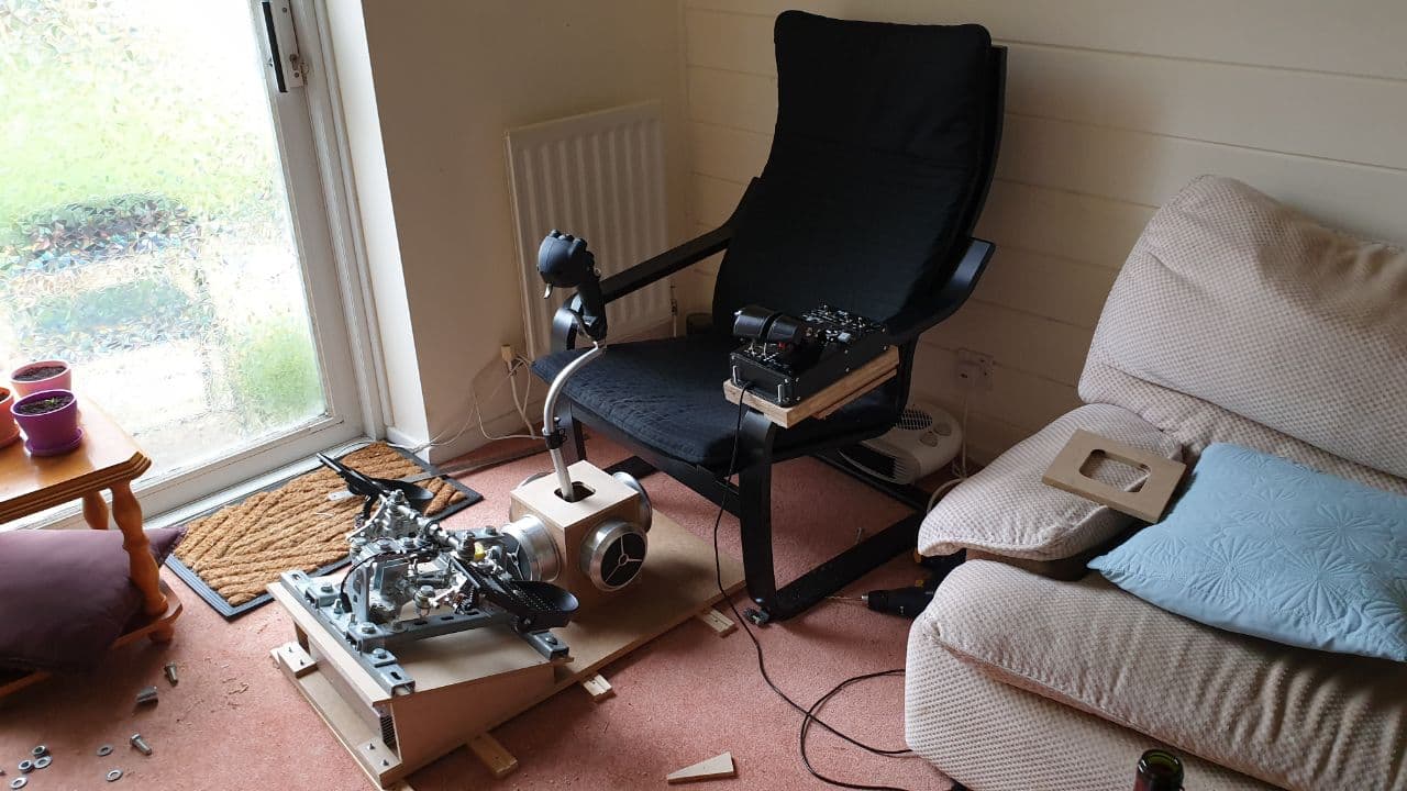
Progress so far on mine - gimbal and joystick mechanics are done, just finishing off wiring for the end point hall sensors then I'll be looking at the software side with a view to running the joystick as a "standard" joystick with no force feedback for the time being, just using the hoverboard motors for centering (so I can continue flying!) and moving on to full force feedback soontm. I had issues using the SPI bus on the TLE5012B encoders I have, so they're currently working as ABI rather than absolute - also I've had issues updating the firmware on my ODrive (which may or not be related to the SPI issues), but I now have an ST-Link V2 so I'll try updating the ODrive to the latest firmware soon. I'm between two minds as to using the ODrive entirely for the electronics, or adding an Arduino as the interface between the PC and ODrive and running the ODrive via PWM signals (or other communication, maybe UART?) - currently only two motors are powered, but if my plans come to fruition, I'm thinking of using one motor on each axis for the centering force, and the second motor on each axis for impulse forces, but I'm not sure if/how that would work. Bootup and centering for now will be using end stop hall sensors and the index of each live motor mechanically set to the center point of each axis as I do not have an absolute reading on the encoders. The pedals were also DIY, from a few years ago - still running strong
-
Honey, I developed FFB joystick (DIY)
SquidgyB replied to propeler's topic in PC Hardware and Related Software
Hello there! I'm in the process of building my own FFB joystick using hoverboard motors, an ODrive and off the shelf/home-tool modified parts. The "prototype" (likely also end product!) is currently being assembled and built - I'm looking at an MDF box with 2 live hoverboard motors, and two (currently) disconnected motors (it's actually cheaper to buy broken hoverboards than bearings, and driving another two motors requires an additional ODrive unit an what I can only imagine would be a fairly decent amount of work to get them talking to each other - and the PC, as one unit, controlling 4 motors set on two axes), a gimbal built from aluminium 3D printer shaft clamps (SK16), a car propshaft/steering universal joint spider, and some carbon fibre and aluminium tubing and aluminium block/plate. I have a (very) small lathe, small milling machine/drill, bench sander and disc cutter, so the tools I'm using aren't crazily unobtainable, but I do have a little garage workshop setup. I'll post some photos once I have something that isn't just a pile of random bits, but my main question/request goes to propeler - could I possibly also have a copy of the firmware you're using for the ODrive? I'm looking at using the TLE5012 encoders - I'm not sure if that's the same or significantly different to the ones you're already using? -
Mine fails to start since the WMR update too - seems that following someone's advice and running WMR first, then *DCS* (allowing SteamVR to start automatically) fixes it. I haven't tried rolling back WMR for now, I can live with the slightly modified starting order for the time being.
-
I think some mods (specifically the VR Zoom Mod, in my case) break the Esc/Pause (and some other) functionality. I found disabling this mod fixed it for me.
-
It would indeed be great if the mouse in VR moved relative to the cockpit (like it does in the menu/title screen) and not tied to the head movements, or at least the option to disable being tied to head movements. Using a mouse to click switches in VR can be quite frustrating when little head movements mean the mouse moves away from the switch you're trying to get to - *but* I can also see that it might be an issue with persepective when looking at switches to the side or hidden behind objects, and lateral movement also coming into play?
-
That issue *should* be resolved now, providing you're up to date with Windows: https://www.rockpapershotgun.com/windows-10-fixed-the-recent-game-performance-problems