flx54
-
Posts
27 -
Joined
-
Last visited
-
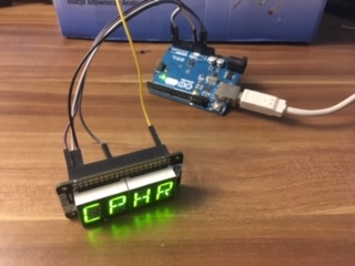
UPDATE: BIG SUCCESS !!! I managed to get Display 1 of the UFC to show correctly on the 4 digit 14-segment display using this code. (Nothing special for (FSF)Jan (THX A LOT !!!) but i guess but thought i´d share with you) // include Adafruit LED Backpack library #include <Wire.h> #include <Adafruit_GFX.h> #include "Adafruit_LEDBackpack.h" // include DCS-BIOS Arduino library #define DCSBIOS_IRQ_SERIAL #include "DcsBios.h" // display instance Adafruit_AlphaNum4 alpha4 = Adafruit_AlphaNum4(); void onufcOptionDisplay1Change(char* newValue) { alpha4.writeDigitAscii(0, newValue[0]); alpha4.writeDigitAscii(1, newValue[1]); alpha4.writeDigitAscii(2, newValue[2]); alpha4.writeDigitAscii(3, newValue[3]); alpha4.writeDisplay(); } DcsBios::StringBuffer<4> ufcOptionDisplay1Buffer(0x7432, onufcOptionDisplay1Change); void setup() { // initialize display alpha4.begin(0x70); // write something to the display // so you see something before data is received alpha4.writeDigitAscii(0, 'A'); alpha4.writeDigitAscii(1, 'B'); alpha4.writeDigitAscii(2, 'C'); alpha4.writeDigitAscii(3, 'D'); alpha4.writeDisplay(); DcsBios::setup(); } void loop() { DcsBios::loop(); } For Connection i used this reference: https://pinout.xyz/pinout/four_letter_phat Pin A4 is used for DATA Pin A5 is used for CLOCK Now i dont know whether the colon in front of the symbols needs a fifth digit or could be adressed separately?!
-
OK, i think i messed up. Trying to clean up the libraries even after uninstalling the IDE. Cant include dcs-bios.h as it is already installed somewhere else. I need to check for a clean uninstall before continuing i guess. Whats the best option to include the library for DCS BIOS? Add the zip or place the uncompressed folder into the library folder of the IDE?
-
Hi Ian, thanks for your input and useful hints. I already found "display1" in the hornet section with which i want to start testing. I guess there is not much more for me to do, than spending more time with it and understanding the logic. I think, that this is going to work well as winter nights are very long... :D
-
I am at the same stage. Copy and Paste. Not much more for me to do, as i am not experienced in coding or whatsoever. I2C is a must as far as i see, because of the simple connection. Dont want to code every pin/segment of the display myself. The PCB size does not matter in my opinion as you could 1st: modify the 3d STL file to fit your PCB or (easier) wire the LED pins to the PCB (detach PCB from LEDs) and place the PCB somwhere else... BTW: the 0,54" LEDs are too large anyway. Looking for green/yellow 0,39" I mean this sort or similar: https://store.arduino.cc/10-jumper-wires-150mm-male
-
It´s actually not sooo dificult. Soldering is. I am not too talented in soldering and it therefore took me quite some time with some very cheap equipment. Now i will try to add the appropriate lines from DCS-BIOS in the right place. Will see how long it takes me to get this right...
-
Cool. Didnt know this thread. Will have a look onto it. Many thanks! Currently investigating how to get these "snippets" from DCS BIOS to work on my project...
-
Thought i´d share with you. ;)

-
Wonderful, this is how it should be. Winter is coming, and I will be experimenting at home. Cool! And I will give this one a shot. See how far I get and which 14-segment LEDs I can solder to it. it´s been made for 2 sets of 2 digits, probably its possible to connect more than that?!: https://www.adafruit.com/product/1910 Thank you for your inputs and many thanks to Ian for DCS BIOS! :thumbup:
-
THX for that. I will try to do that. What fits DCS BIOS better? Common Anode or Cathode? Remembering, that Mobiflight and another civil sim were only compatible with one sort of...;)
-
Exactly my point. The standard HT16K33 backpack comes also as a kit with too high displays. But can I "simply" attach smaller ones to this board? Pin layout should be the same I guess. best regards
-
I got my UFC now printed by a friend and investigating hardware (cheaper) options here in Europe. AFAIK a 14-segment LED will do fine. I plan to use 10mm digit height, 4 up to 8 digit tubes. Of course they are from well known Chinese sources. Problem is, that they don't supply the backpack/driver board to interface it i2c wise, which would be way too much wiring/soldering. Any ideas which 14-segment displays I could use with ease? I saw the 4 digit Adafruit solution but the digits seem too large for the UFC... Have a great Weekend! flx54
-
Wish i could test it by myself, but i still dont get it running. Looks like it is not exporting. Can someone with the Android UFC working please post his/hers export.lua file? Thanks!
-
Capt Zeen F/A-18C Beta Helios Profile ! ! !
flx54 replied to Capt Zeen's topic in PC Hardware and Related Software
From the readme and what I followed: Ok, this is important to know, Helios do not export the viewports, is DCS who do that. Some DCS modules are ready to export some of his viewport, but not all of them. That's the reason we need to change some .luas to make that module ready to export the viewports. In the F18 case, and at this date ( 07/30/2018 ), only the 2 DDIs are ready to export. The AMPCD, IFEI, RWR and UFC are not, so we need to overwrite those .luas with other ones ready to export viewport. Usually, in my profile packages you got everything you need to do that operation in a folder called monitor configuration. So... - Check if you installed the files in the correct place. I recomend to you use JSGME or OVGME to do the job, because in every DCS update those files are rewriten again - Then edit the MonitorSetup file to adjust the viewports to your monitor configuration. (2_monitors-FA18C.lua ) - In DCS options, put your max resolution ( this is the total of your monitor resolutions in horizontal and vertical, for example two monitors 1920x1080 placed in horizontal layout, the total resolution is 3840x1080 ) - In DCS options, uncheck full screen option - In DCS options, select the monitorsetup file to use (the one your just edited) So in the Zeen FA18 package update 2 there is a folder called MonitorConfiguration->Mods->aircraft->FA-18C-Cockpit->Scripts and there you find the IFEI,TEWS and UFC files. ;) -
Capt Zeen F/A-18C Beta Helios Profile ! ! !
flx54 replied to Capt Zeen's topic in PC Hardware and Related Software
Same here. Need to check the lua file again but IFEI disappeared as well... :/ OK, guess i found the solution: From the Hornet package, you need to substitute the scripts again. These are: IFEI_init.lua, RWR_ALR67_init.lua and UFC_init.lua. (Obviously overwritten by the update...) Tried it with IFEI right now and works as it should. -
Hi, as i am also interested in building an UFC on my own i am wondering, what is the correct choice for segmnt LEDs? Are these 14(16)segemnt LEDs used in the real Hornet or is it more like a matrix LED style (like we see in the Sim) Anyone knows? THX?