

Brun
-
Posts
573 -
Joined
-
Last visited
Content Type
Profiles
Forums
Events
Posts posted by Brun
-
-
The pin should be easy enough to remove without disassembling anything, it's an M3 thread so just find a suitable screw. Might need something pointy to rotate the empty hole into a better position. Once you've separated the left and right throttles, remove the screw and the pin can be pulled straight out.
You can also use an M3 screw as a replacement, however the head may need to be cut off to prevent it fouling the throttle handle.
Edit: Just realised it's broken rather than just unscrewed. Guess that makes putting another screw in impossible, but I'd still expect you can release it from the current state and remove the pin using something suitably pointy.
-
Recommendation for a 1200W PSU seems wildly over the top.
In to addition the hardware in my sig, I have 2x M.2 SSDs, 3x SATA SSDs, water cooling pump, 8x 140mm fans, plus a whole load of USB devices powered directly from the PC.
All that running perfectly fine with a meagre Corsair HX850. It's plugged into the wall via a power meter and I've never seen it draw more than 650W. People suggest that power meters aren't sensitive enough to detect short spikes in demand, but I've not had a single issue that might have been power related.
-
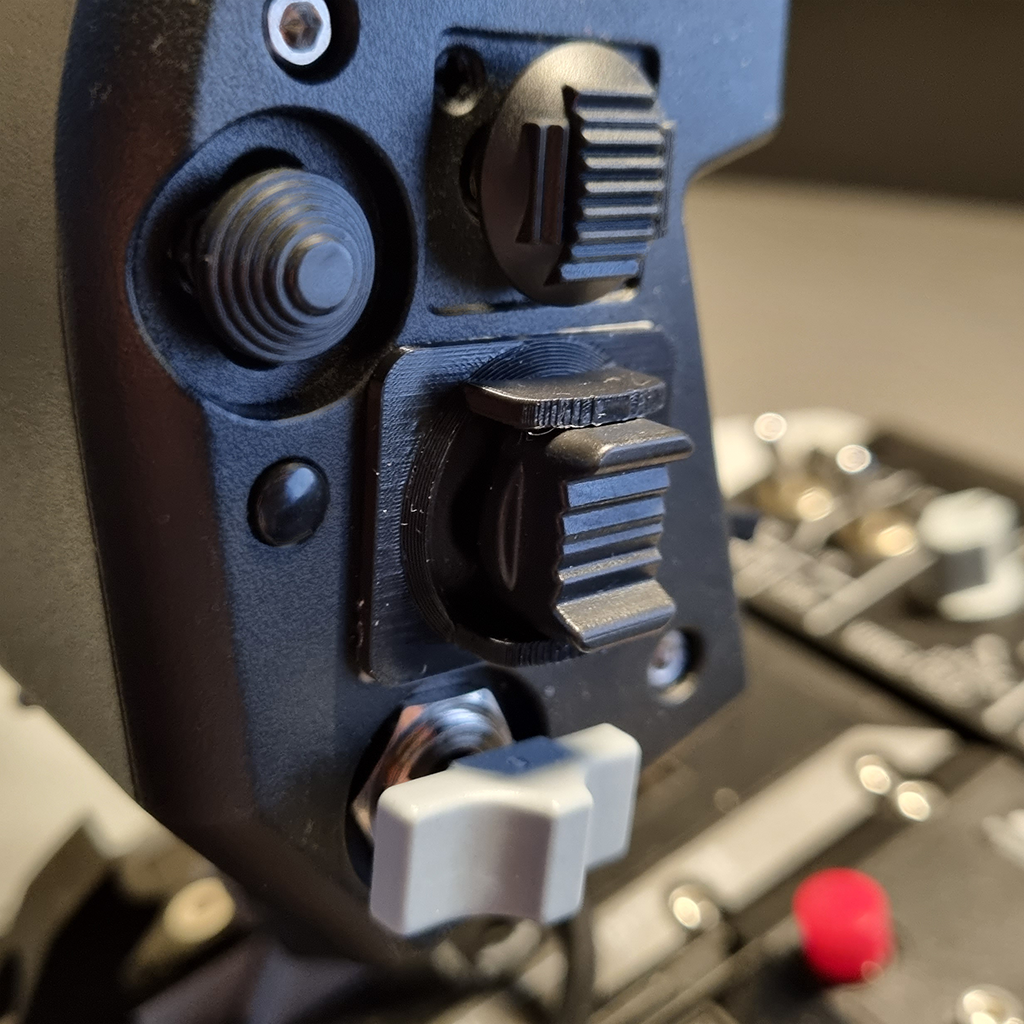
It seems a bit weird to deliberately reduce the number of available buttons, but I wanted to simplify one of the F15EX switches by limiting its movement to just forward and backward. A very simple 3D print later, works exactly as I wanted.
STL attached if anyone else fancies it. I just used double-sided tape to attach, which seems perfectly sufficient.

-
 1
1
-
-
3 hours ago, Assamita said:
I know for RAM the lower CL number, the better, but also the higher the frequency the better too, so I'm debating between two Corsair Vengeance LPX kits. One is 3200 CL16 for 129€ and the other is 3600 CL18 for 149€. I assume, since the latter is more expensive, that it's better to have a higher frequency, even if it's at a cost of a slightly higher latency, but what are your thoughts about it?
Overall latency is a factor of speed and CAS latency (CL). You can compare the two kits using this calculator and see that they're actually identical in this respect. If the extra cost isn't an issue, I'd go for the 3600.
-
1
-
-
Nick Grey's comments certainly don't inspire any confidence in a 2024 release. Around 25 mins into the video...
-
1
-
-
Definitely sounds like an application 'capturing' those keys and preventing them being passed though.
I'd suggest opening task manager and see if that shows what might be responsible. Force-quit anything that looks like it could be, checking after each whether the keys start working again.
-
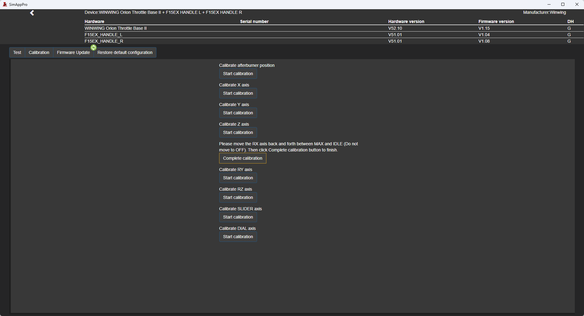
On the calibration page, which currently looks like this?
-
Having got the impression that this board was at least monitored by WinWing, I thought it worth posting here...
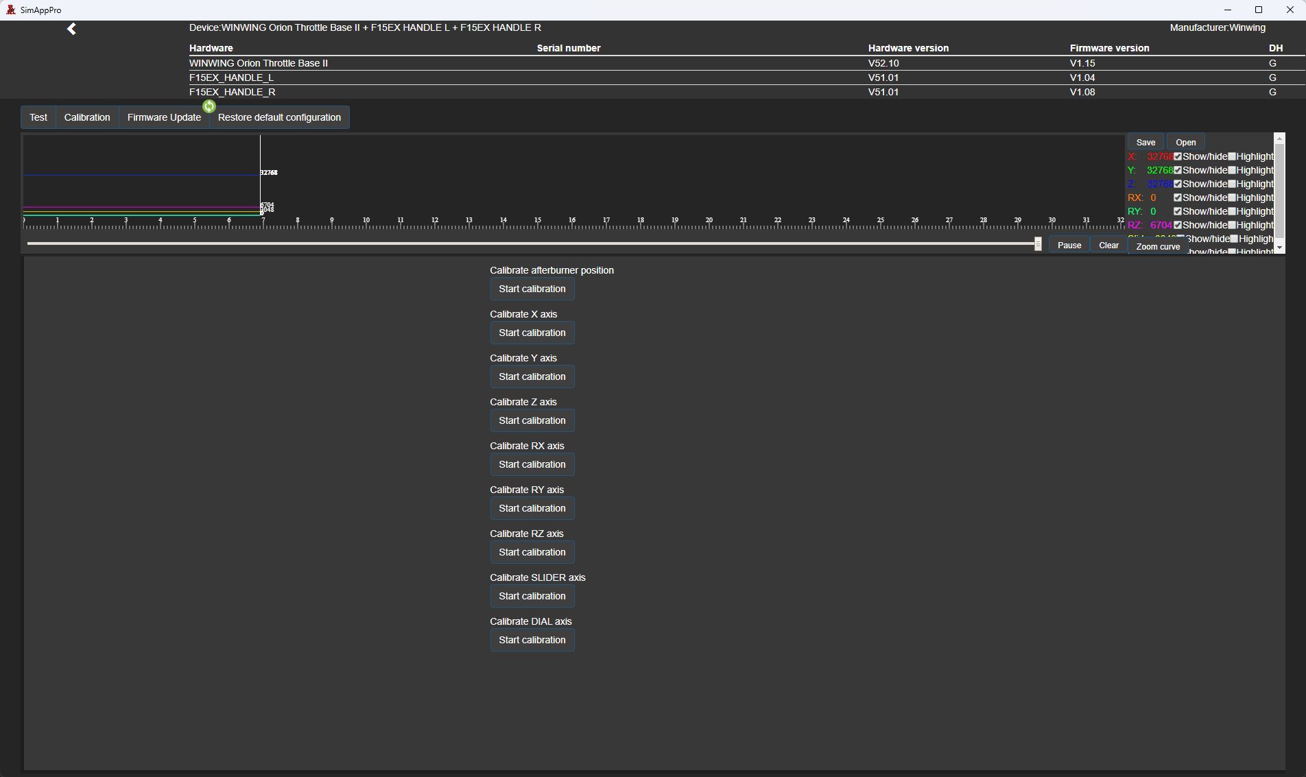
While calibrating my throttle it occurred to me that the axis values should be visible on the calibration page. Two reasons...
1. There's currently no way to identify each axis without going back to the 'test' page. Having to do this repeatedly is annoying.
2. It's useful to be able to see raw axis values while calibrating.
Simple photoshop mockup...
-
6 hours ago, Scott-S6 said:
Cities don't need raytracing because the light sources and the buildings are static.
The most significant light source in DCS is the sun, and that's definitely not static. Neither are the cockpits which it casts shadows into, or aircraft it casts shadows from.
While I would agree that there are fewer benefits to ray tracing in DCS compared with other applications, it should at least make shadows more accurate and less prone to issues. It's also important to distinguish between ray traced direct shadows and bounced lighting from diffuse surfaces (aka global illumination or GI), the latter being what baking seeks to address. As far as ray tracing is concerned, they're independent of one another and direct shadows could be ray traced without the performance hit of calculating indirect lighting.
-
22 hours ago, Marshallman said:
It came recently developed for eye tracking, then he expanded it to fixed
What 'it' are you referring to?
Fixed foveated rendering has been part of the toolkit for ages, long before Matt developed the eye tracking stuff. It uses a method called Variable Rate Shading, which is nothing to do with quad views as far as I'm aware.
It's been suggested upthread that the foveated rendering of quad views is better than that of the toolkit, even for users of headsets without eye tracking. I'd just like to know what that's based on, or see some evidence for it. Have had a read of the documentation and failed to see anything there, apologies if I've missed it.
-
On 12/6/2023 at 8:44 AM, markturner1960 said:
Just quoting the great man from his wiki instructions
Where does he say one is better than the other?
I had a look into things and it appears that they use different techniques, but if the quad views method is superior why wouldn't Matt have used that in the toolkit?
-
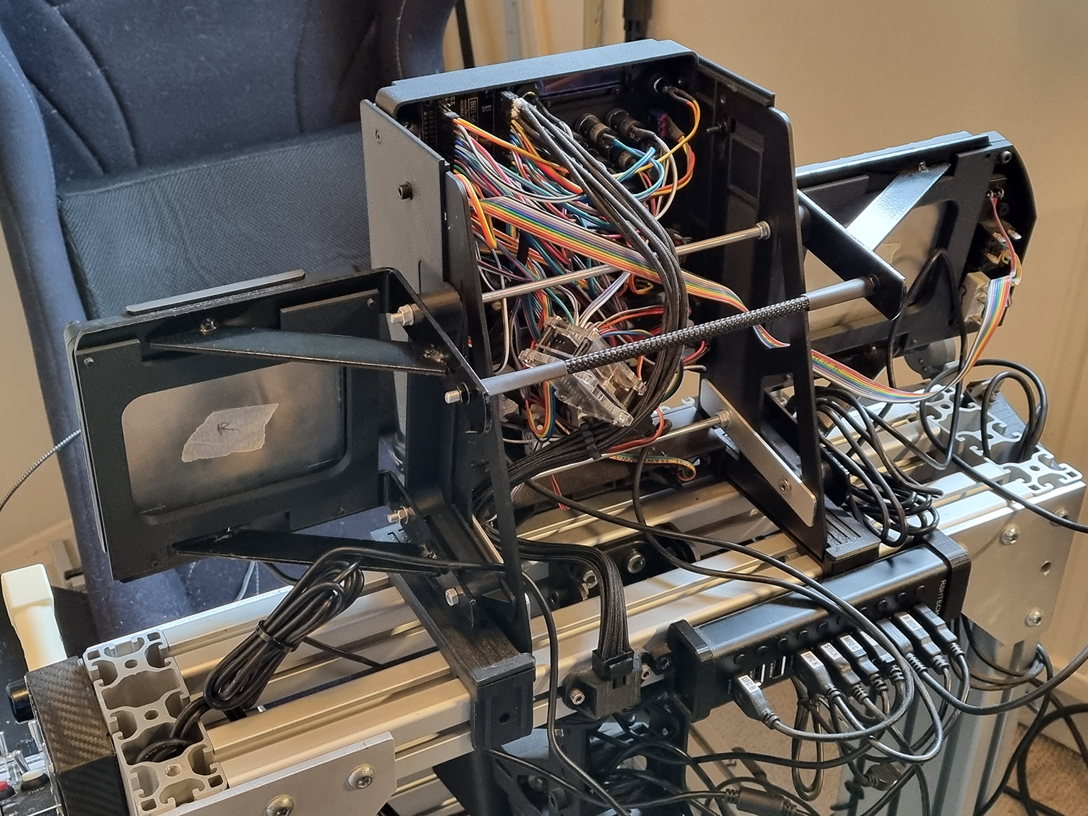
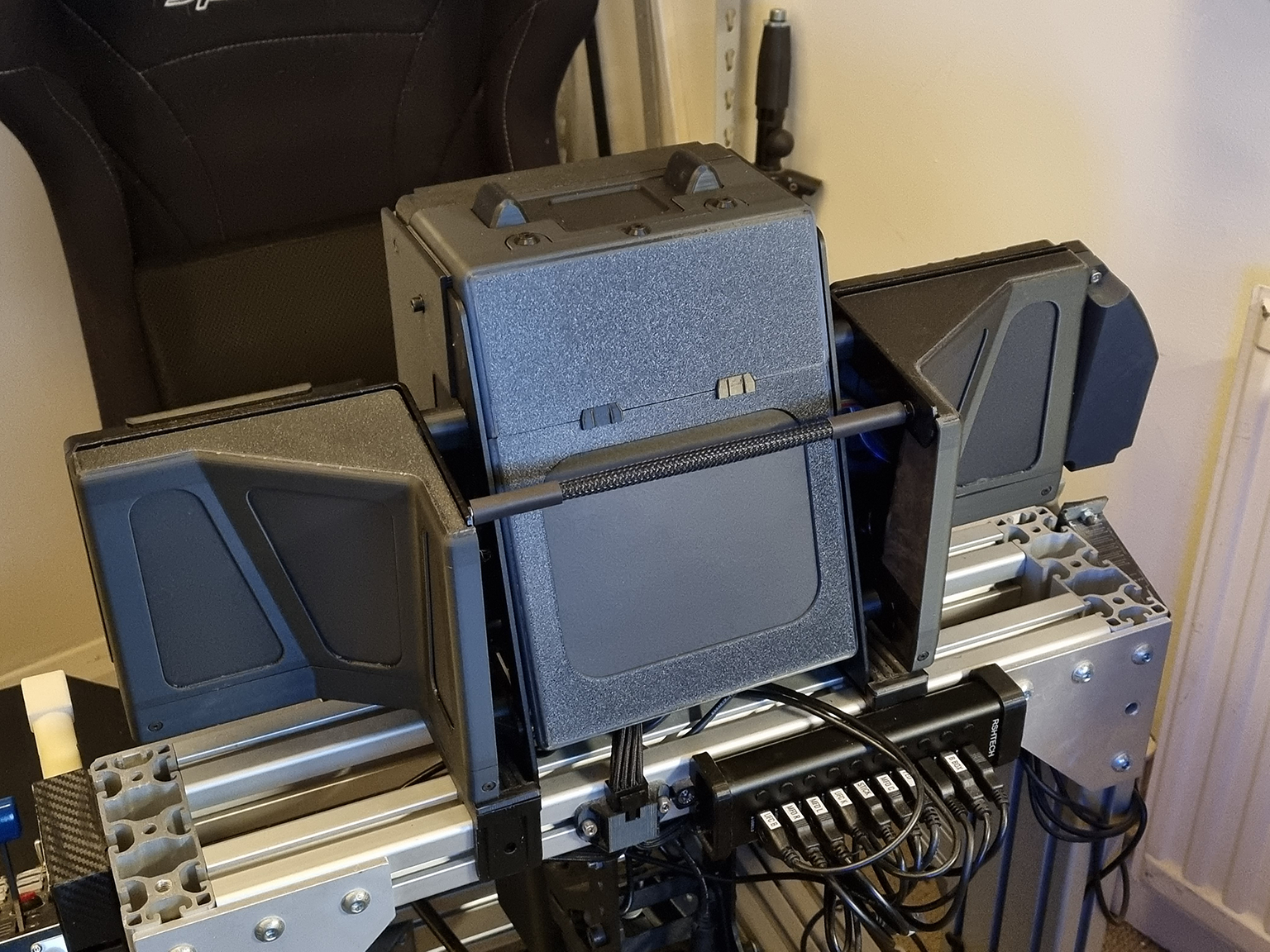
It's taken a while, but with the recent arrival of a Bambu Lab P1S I've finally done something about the mess that was visible from everywhere but the pilot's seat.
Before...
After...
-
On 11/21/2023 at 10:52 PM, Jive said:
Something pretty nice is using Quadviews by mbucchia https://github.com/mbucchia/Quad-Views-Foveated/wiki
With a 4090 you can probably set the outer as a PD of 1.0 then try the inner at something like 2.0
I have a 3080ti so it's not quite enough horsepower for me to run it consistently but it looks super niceFor a headset without eye tracking, what's the difference between this and the fixed foveated rendering in OpenXR toolkit?
-
They don't take any payment info at all when pre-ordering. On the global store at least.
-
Going back to the OP, I struggled to fully understand this as well. My Orion2 F-15EX *with finger lifts* arrived today and I think I understand more clearly now.
The throttle handles don't connect directly to the throttle levers on the base, the finger lifts fit between each. That being the case, I'm assuming that the 'dual throttle connectors' are just a pair of simple adapters without the finger lift mechanisms.
-
13 hours ago, Toga10 said:
From my understanding they just used the 3d model, all textures etc are made by Dino. They were just using it to get more accurate measurements.
IFE's comment on the facebook post: "The geometry provided by True Grit is extremely accurate, but we may have to slightly rework the textures for Flight Simulator."
I would guess that's in relation to how maps for roughness, metallic etc are handled differently between DCS and MSFS.
-
1
-
-
I put in a pre-order for throttle + F-15EX grips on August 3rd. Got the email saying they were in stock on the 25th, and they're now on the way.
It's worth noting that they don't take any money when you pre-order, it's effectively a no-obligation reservation. The in stock notification gives you 48 hours to complete the order.
-
1
-
-
New Channel 4 (UK) series about the RAF... https://www.channel4.com/programmes/top-guns-inside-the-raf
These things always tend to focus on the people but there's bound to be some decent footage as well.
-
1
-
-
I think it helps to think of IAS as an indication of aerodynamic performance rather than simply speed. Near the ground they're closely related but as you have noticed, become more divergent with increasing altitude.
-
I'm also very sceptical that the real aircraft requires such absolute precision. The stick being 'centered' does not explicitly mean both axes have to read exactly zero.
Claiming nothing can be done about it despite several people independently suggesting the same perfectly obvious solution is insulting.
-
Having to compromise flight controls like this just so autopilot can be engaged seems completely unreasonable. It's a workaround rather than a solution.
The obvious fix would be for ED to add some tolerance to what is considered 'centered' for the purposes of engaging AP. It can't be that complicated in the grand scheme of things. @BIGNEWY is there a way to make this an official suggestion or otherwise bring it to the team's attention?
-
2
-
-
The Hornet's throttle has a different idle position depending on whether it's on the ground or airborne. This is accomplished by a physical lockout which prevents the throttle being moved to 'ground idle' when in flight, via the weight-on-wheels sensor.
The deadzone you're noticing is simply the portion of throttle travel which is between ground idle and flight idle. Our hardware obviously doesn't have the means to physically prevent it being moved there.
-
2
-
-
On 4/12/2023 at 1:21 AM, Tree_Beard said:
It seems to take a weirdly long time for the flaps to move from 12 to 16, holding back on the trim hat, but whatever I guess.
This also seems consistent with flaps being set to AUTO.
I'd noticed previously when preparing to take off that the trim didn't seem to change at all until I set flaps to HALF. When checking again it does, but slowly.
-
Hook bypass switch will make the AOA indexer flash if it's not set to 'field' and the hook is up. Been a while since I ran into that tho and I don't remember it triggering master caution, unless that happens at a specific altitude AGL?
Will the eurofighter be able to use nvgs and hmd at the same time?
in DCS: Eurofighter
Posted · Edited by Brun
I guess the question should have been 'can the HMD and NVGs be used during the same flight?'
In contrast to - for example - the Hornet, where you have to tell the ground crew which one to install.