Gadroc
-
Posts
1060 -
Joined
-
Last visited
-
Days Won
1
Content Type
Profiles
Forums
Events
Everything posted by Gadroc
-
Major Announcement: New software to to connect panels to DCS
Gadroc replied to FSFIan's topic in Home Cockpits
Flem that's shaping up nicely. A few recommendations: 1) Don't modify DcsBios files directly unless your trying to submit a patch. It will bite you when it's time to upgrade. You can create cpp and h files inside your sketch or create a second libraries folder containing all you add-ons. 2) Don't depend on externally defined globals if at all possible. In your current code anyone who includes DcsBios.h will be required to define the global leds variable even if I'm not using shift registers. Better to pass in a pointer to the leds in the constructor. This would allow me to have two shift regsiters on different pins... or string two 8 bit registers together. 3) Don't update the shift register in the main loop. You should wait for the bios write on address 0xfffe. The update shift register is a slow operation and could interrupt processing data off the serial port if done where you have it right now. -
Don't need to enter the IP address on the second PC... you point the flight sim computer to the second PC's ip address. The second PC listens and will automatically detect the flight sim PC's address.
-
Very nice work there. What font are you using for the text? I have an updated MS33558 where I've added a few missing symbols (punctuation, parenthesis, etc...) and cleaned up the spacing and hinting.
-
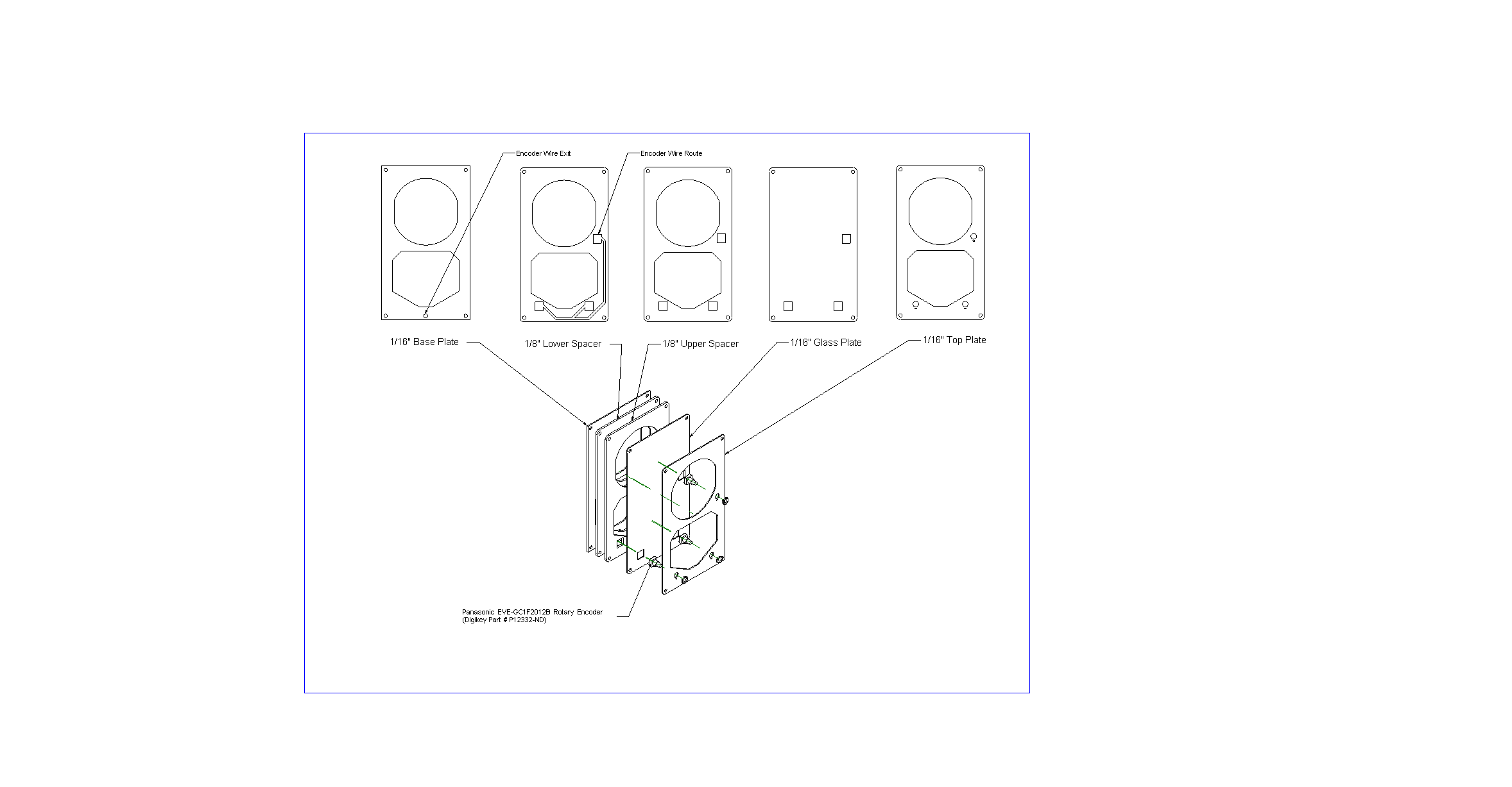
Here is the bezel I designed. It's supposed to house three Panasonic EVE-GCF2012B encoders. It's designed to be cut out of 1/8" and 1/16" black acrylic and one piece of 1/16" clear acrylic. If you don't want to have the clear windows just cut upper spacer twice. Once in 1/8" and once in 1/16". Glue the spacers and top plate together, paint if desired and then wire and mount the encoders. Fasten to MIP holding base plate and spacer in place with screws. EFIS Bezel.zip

-
I have an AT090TN10 panel which is just about a perfect fit in the MIP if put in portrait mode. You'll have to reduce the height of your HSI / ADI by a little than the real thing. I have bezels draw up in cad for this if you want me to post them up. This is what I was going to do before I got the real ADI working.
-
I concur with Ian. A 21"-24" 1920x1080 monitor is best with Helios. Most profiles are geared towards that and with creative use of sub-panels you can really fit everything you need to fly and still be readable. My original Helios cockpit was 3 1920x1080 touch screens (center, right and left consoles). There are many days I wish I stuck with that as I'd fly more than tinker with the pit... then I look at the pit again and get excited about building it.
-
Major Announcement: New software to to connect panels to DCS
Gadroc replied to FSFIan's topic in Home Cockpits
Yes the Leonardo should work, and no you won't need to manually reset it. -
Major Announcement: New software to to connect panels to DCS
Gadroc replied to FSFIan's topic in Home Cockpits
Probably best to post those kind of questions onto a programming / microcontroller forum. You'll progress faster if you break down problems. If you're trying to learn shift registers separate that task from the cockpit. The forums over at arduino.cc are a great source for questions like how to use a shift register. You might also try checking out the AVR Freaks site (http://www.avrfreaks.net). Once you know how to read and process shift registers come back and combine that with the DCS-BIOS library. The same goes with anything else related here. If you want to do an LED output, make sure you understand how to do an LED safely with out DCS-BIOS first (You can't just connect one with out some math unless you want to possibly fry it or your arduino board.) That being said you need to learn and operator (&), or operators(|) and bitmasks. -
Major Announcement: New software to to connect panels to DCS
Gadroc replied to FSFIan's topic in Home Cockpits
Did some more timing this morning using CodeToads sketch. processChar takes about 13-14us in when not calling onDcsBiosWrite processChar takes about 60-66us when making a call to onDcsBiosWrite (w/o LCD update) processChar takes about 16ms when making a call to onDcsBiosWrite (w/ LCD Update) pollingInputs takes about 11-13us I have to do the math to figure out max baud rate without loosing data on that one... 250k still seems to miss some things on the initial load. -
Major Announcement: New software to to connect panels to DCS
Gadroc replied to FSFIan's topic in Home Cockpits
Nope us and ms are quoted correctly. Yes it's possible that here is no data in the pause or its how long polling inputs takes. I'll throw a few more pins and see what's happening tomorrow evening. -
Major Announcement: New software to to connect panels to DCS
Gadroc replied to FSFIan's topic in Home Cockpits
Verified. I measured CodeToad's code on the scope by modifying the following code: void setup() { Serial.begin(500000); lcd.begin(20,4); lcd.clear(); pinMode(2, OUTPUT); digitalWrite(2,LOW); } void loop() { while (Serial.available()) { digitalWrite(2,HIGH); parser.processChar(Serial.read()); digitalWrite(2,LOW); } DcsBios:: PollingInput::pollInputs(); } I then dropped my scope on pin 2 and set it up to trigger on any pulse where it sat low for over 3ms. Sure enough there is a pattern. There will be 6ms where things process normally with it taking between 20-60us inside processChar and 20-40us between calls to processChar. Then there will be a 30ms delay where processChar is not called. This cycle is repeated over and over again. During that 30ms pause between calls to processChar you'll loose approximately 10 sets of data assuming the 3ms transfer rate you quoted earlier. Running the same thing using 250kbps. A similar pattern appears 7ms of normal processing followed by a call to processChar that takes 16ms followed by 16ms pause before calling it again. Running again at 115.2kbps, we see 11.8ms of normal processing, 17ms processChar call followed by a 16ms pause. -
Major Announcement: New software to to connect panels to DCS
Gadroc replied to FSFIan's topic in Home Cockpits
Possibly, but he's defined 6 string buffers as well. Each string buffer and onDcsBiosWrite is called for every other byte of every message. It might be fine, but seems like a lot unnecessary calls getting made. Might be better to only call onDcsBiosWrite once per message and let the callbacks handle indexing into the message. I'm in the middle of getting my environment set up to test / code for DCS Bios. Once I get it going I'll put in a pin toggle before and after processChar and then drop a scope on that pin to get some timings of how fast that's happening. -
Major Announcement: New software to to connect panels to DCS
Gadroc replied to FSFIan's topic in Home Cockpits
My bet is the problem was actually buffer overrun, and not signaling error. The buffer on default arduino serial library is only 63 bytes. So at 500,000bps if your work between each serial.read is over 1.5ms, the buffer will loop and you will be missing data. This is very plausible with how the Arduino library is structured right now. It polls all inputs, parses data, interrupts data and bit bangs it out to the LCD before coming back to reading the next character. -
Major Announcement: New software to to connect panels to DCS
Gadroc replied to FSFIan's topic in Home Cockpits
I use 250,000 on all of my arduinos and RS-485 for that reason. The only down side is 250,000 is a non-standard baud rate, so some PC hardware/software has problems with it. That is a very small subset though. -
Looks good!
-
Annoying constant roll to the left !
Gadroc replied to Jateu's topic in PC Hardware and Related Software
Two possible items I can think of. 1) Do you have multiple direct x controllers? By default my pedals toe brakes where mapped to ailerons... the caused quite a bit of excitement when using the rudder. Check all inputs axis and clear any you're not using. 2) The hog needs trimmed all the time. Change air speed and you'll need to re-trim. Breath a little heavier and you'll need to re-trim. That being said I usually don't need to trim bank, just pitch. So check #1. -
Unfortunately Helios does not currently send keyboard actions remotely. You can bind anything to the DCS A-10C Interface... but any bindings to keyboard are to the local keyboard not the one running on the DCS computer. Some people have worked around this in various ways (screen sharing applications, etc...)
-
bengo, Install helios on both computers. On your flight sim computer open the profile editor and create a new profile. Add the A-10C interface to it. Enter the ip address of your laptop and click setup DCS A-10C. You can now close helios and you don't need to run it on the flight sim pc. Open helios on the laptop and create your profile. Add the A-10C interface to it. You don't need to click setup DCS on this machine. Configure your profile and bind to A-10C as needed.
-
Digital-To-Synchro converter for interfacing real aircraft indicators
Gadroc replied to brydling's topic in Home Cockpits
Correct and I've already accounted for it there. I'll need to check the mil spec at where the electrical zero is to see if I've wited properly. -
Digital-To-Synchro converter for interfacing real aircraft indicators
Gadroc replied to brydling's topic in Home Cockpits
Finally got my boards hooked up and running my ARU/2B ADI. Worked well first time! The one question I have is when I set the angle to 0 it is actually -60. This is trivial to offset in software, but does it mean I have something wired wrong? The Milspec on my ADI lists the input to the syncros as x, y and z not s1, s2 and s3. I just wired s1-x, s2-y and s3-z. Would rotating those change anything? -
Woo! Got all the wiring done for the ADI using Brydling's DTS cards. I also finished the code integration which allows Helios to drive them. Here is a quick (and bad) video of the ADI being controlled via push buttons in Helios. I have one more part to pick up (MOSFET to drive lighting) and then I'll be able to move it back into the pit fully functional!!
-
The gimball is driven by synchro motors (http://en.wikipedia.org/wiki/Synchro). There are two in the ADI one for roll and another for pitch. I will be driving them using Brydling's Digtial-to-Syncrho(DTS) Boards (http://forums.eagle.ru/showthread.php?t=112902).
-
Back in the sadle again. Finally finished the control board for the ADI. Here it is running a test sketch with the real wiring harness and control board. Tomorrow I'll get the firmware connected to helios. I need to finish wiring the power supplies and DTS boards tomorrow as well and I should have spinning ball as well.
-
I understand that. Extracting data from the sim is not straight forward and requires a lot of train an error to interpret the values correctly. My intention is right now to make Helios a client to DCS-BIOS but still drive EOS via Helios and not connect DCS-BIOS straight to the Arduinos. This will allow me to drive out of game logic with the hardware switches easier.
-
A great start would be someone wanting to help with DCS BIOS integration and extending DCS BIOS to do BlackShark and FC3 (Limited Data Available but can pull some sim data).